
Jerseyan
Design by John D'Ottavio Article by Tom Niebuhr
John D'Ottavio has been involved in CL aerobatics (stunt) for decades. He has been a Nats judge and an FAI Team Trials judge and has mentored and coached many top fliers, including Ed Elasick, Dawn Cosmillo, Bill Simons, Windy Urtnowski, the author, and others. At 80+ years of age John remains active as a judge, coach, and competitor. Windy Urtnowski and the author consider him a second father.
John's published designs include the J.D. Falcon and the Topper profile model that Ed Elasick used to win the 1961 Air Youth Championships. In his heyday John was one of the most competitive fliers on the East Coast. Over the years he designed many airplanes; the Jerseyan is perhaps his best-known design that has not been published until now.
When stunt fliers gather they discuss everything from aerodynamic theory to what they will name their next creation. Those discussions led to the Jerseyan. Art Meyers mentioned a new design he would call the "New Yorker" (Artie won Senior Stunt at the 1960 Dallas Nats with that aircraft). In response, John named his 1961 design the "Jerseyan."
Although the Fox .35 was the dominant engine of the day, design considerations in the early 1960s were similar to those now: debates over airfoils, aspect ratios, and moments. The Jerseyan blended old and new ideas and dominated the Northeast stunt scene for the next five years.
The Jerseyan's first contest was on Long Island, New York, where it took first place. From 1961 to 1964 John recorded 23 firsts, seven seconds, and three thirds with the model.
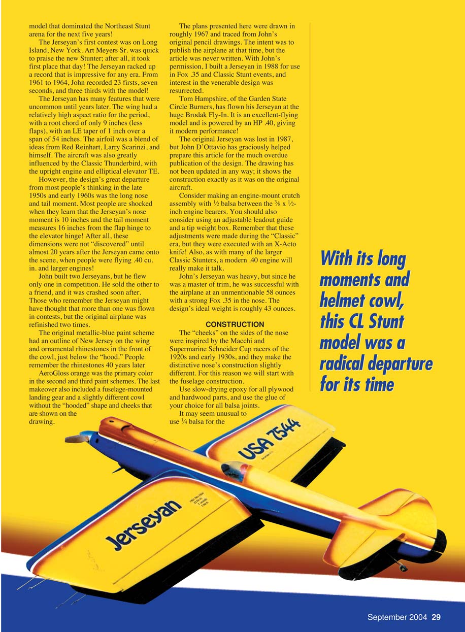
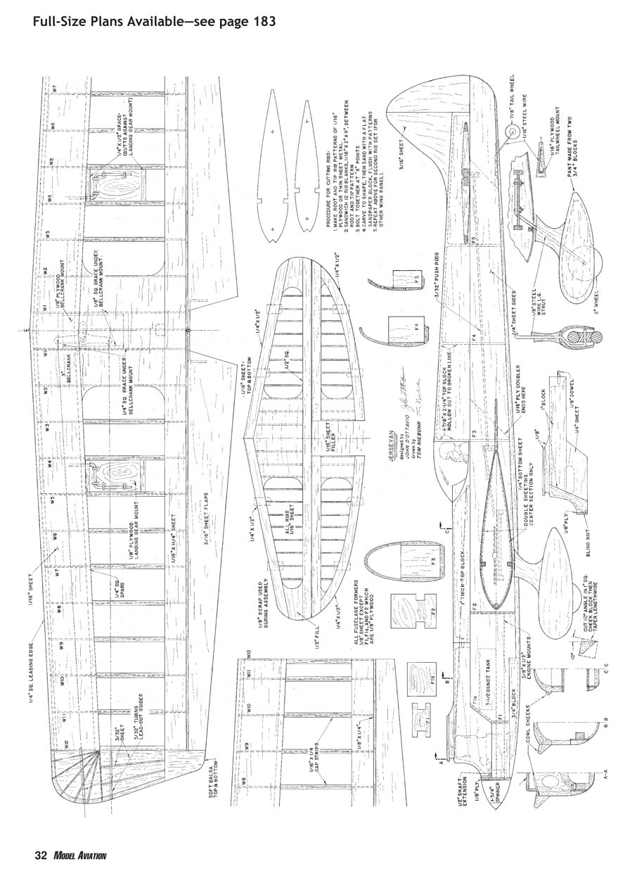
The Jerseyan incorporated features uncommon for its era. The wing had a relatively high aspect ratio for the period: a root chord of only 9 inches (less flaps) with a leading-edge taper of 1 inch over a 54-inch span. The airfoil was a blend of ideas from Red Reinhart, Larry Scarinzi, and John himself. The design was also influenced by the Classic Thunderbird, with an upright engine and an elliptical elevator trailing edge. Its great departure from late-1950s/early-1960s thinking was the long nose and tail moment: the nose moment is 10 inches and the tail moment measures 16 inches from the flap hinge to the elevator hinge — dimensions not commonly used until nearly 20 years later when larger engines were common.
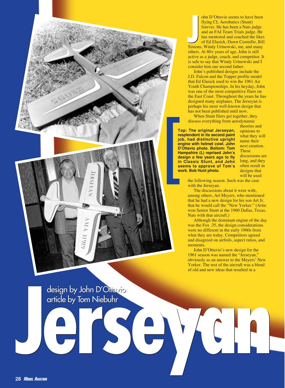
John built two Jerseyans but flew only one in competition; the other was sold and later crashed. The original airplane was refinished twice, which may explain why some recall seeing more than one in contests. The original metallic-blue paint scheme featured an outline of New Jersey on the wing and ornamental rhinestones under the cowl; those rhinestones are remembered decades later. Subsequent paint schemes used AeroGloss orange as the primary color and included a fuselage-mounted landing gear and a slightly different cowl (without the "hooded" shape and cheeks shown on the drawing).
The plans presented here were traced from John's original pencil drawings around 1967. An article to publish them was never written at that time. With John's permission, the author built a Jerseyan in 1988 for Fox .35 and Classic Stunt events, resurrecting interest in the design. Tom Hampshire of the Garden State Circle Burners has flown his Jerseyan at the Brodak Fly-In; powered by an HP .40, it performs very well.
The original Jerseyan was lost in 1987. John D'Ottavio helped prepare this article for publication; the drawing provides the original construction details and has not been updated.
Consider making an engine-mount crutch with 1/2 in. balsa between the 3/8 x 1/2 in. engine bearers. Also consider using an adjustable leadout guide and a tip weight box. These adjustments were made during the "Classic" era with basic tools, but a modern .40 engine will improve performance.
John's Jerseyan was heavy in original trim — about 58 oz with a strong Fox .35 — but John was a master of trim. The design's ideal flying weight is roughly 43 oz.
Specifications
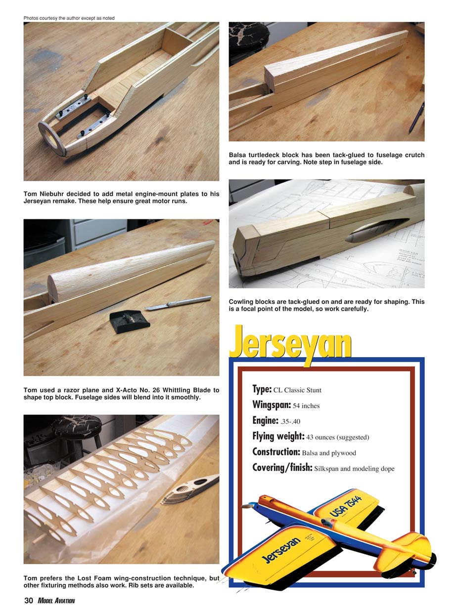
- Type: CL Classic Stunt
- Wingspan: 54 in.
- Engine: .35–.40 cu. in.
- Suggested flying weight: 43 oz (ideal)
- Construction: Balsa and plywood
- Covering/finish: Silkspan and modeling dope
CONSTRUCTION
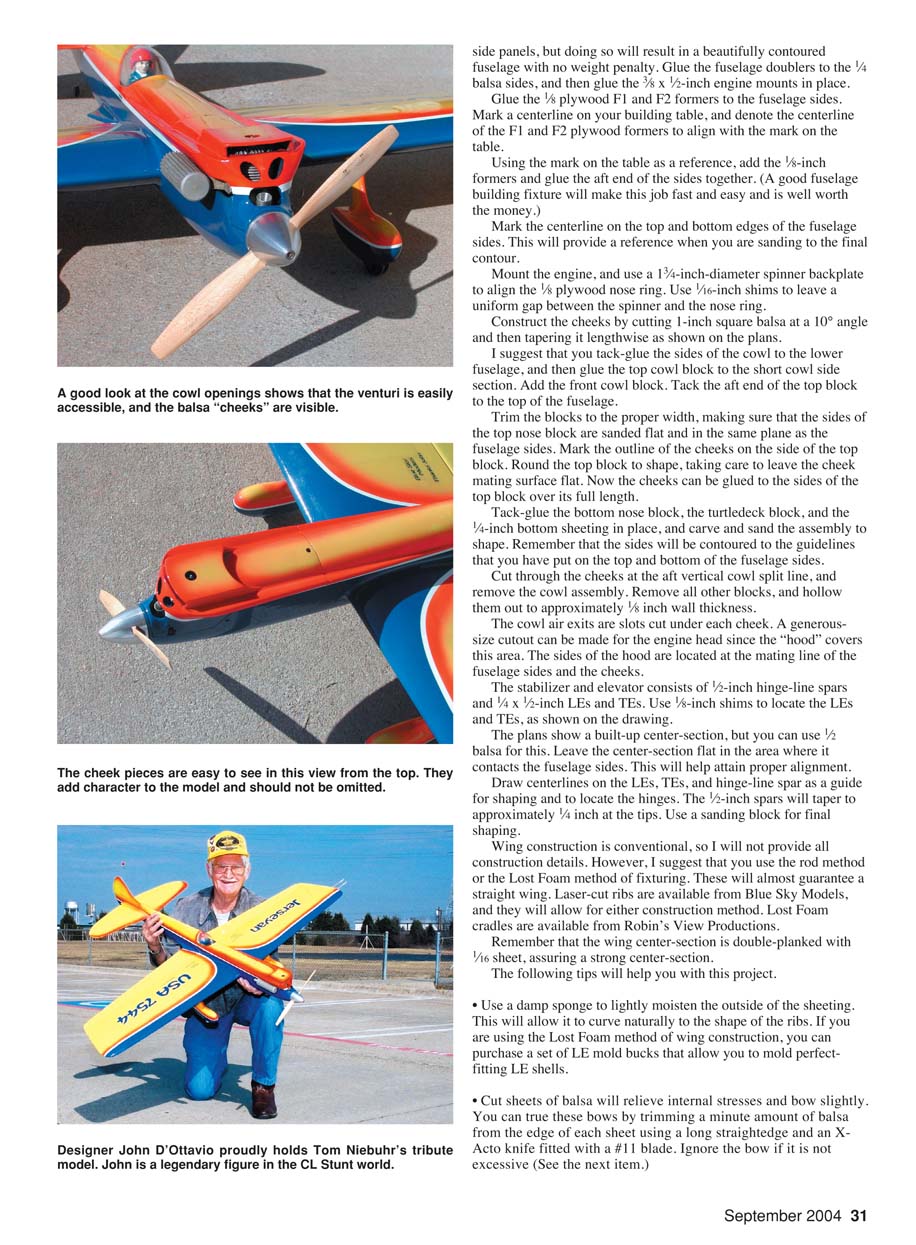
The "cheeks" on the sides of the nose were inspired by the Macchi and Supermarine Schneider Cup racers of the 1920s–1930s and make the nose construction somewhat different. For this reason we start with fuselage construction.
Use slow-drying epoxy for all plywood and hardwood parts, and use your preferred glue for balsa joints.
Glue the fuselage doublers to the 1/4 in. balsa sides, then glue the 3/8 x 1/2 in. engine mounts in place.
Glue the 1/8 in. plywood F1 and F2 formers to the fuselage sides. Mark a centerline on your building table and align the centerlines of F1 and F2 with that mark.
Using the table centerline as a reference, add the 1/8 in. formers and glue the aft ends of the sides together. A good fuselage building fixture makes this job fast and easy and is well worth the money.
Mark the centerline on the top and bottom edges of the fuselage sides to provide a reference when sanding to final contour.
Mount the engine and use a 1 3/4 in. diameter spinner backplate to align the 1/8 in. plywood nose ring. Use 1/16 in. shims to leave a uniform gap between the spinner and the nose ring.
Construct the cheeks by cutting 1 in. square balsa at a 10° angle, then tapering it lengthwise as shown on the plans.
Tack-glue the sides of the cowl to the lower fuselage, then glue the top cowl block to the short cowl side section. Add the front cowl block and tack the aft end of the top block to the top of the fuselage.
Trim the blocks to proper width, ensuring the sides of the top nose block are sanded flat and in the same plane as the fuselage sides. Mark the outline of the cheeks on the side of the top block. Round the top block to shape, leaving the cheek mating surface flat. Glue the cheeks to the sides of the top block over the full length.
Tack-glue the bottom nose block, the turtledeck block, and the 1/4 in. bottom sheeting in place, then carve and sand the assembly to shape. The sides should be contoured to the guidelines you placed on the top and bottom of the fuselage sides.
Cut through the cheeks at the aft vertical cowl split line and remove the cowl assembly. Remove other blocks and hollow them out to approximately 1/8 in. wall thickness.
Cowl air exits are slots cut under each cheek. A generous cutout can be made for the engine head since the "hood" covers this area. The sides of the hood are located at the mating line of the fuselage sides and the cheeks.
The stabilizer and elevator consist of 1/2 in. hinge-line spars and 1/4 x 1/2 in. leading and trailing edges. Use 1/8 in. shims to locate the LEs and TEs as shown on the drawing.
The plans show a built-up center-section, but you can use 1/2 in. balsa for this. Leave the center-section flat where it contacts the fuselage sides to aid proper alignment.
Draw centerlines on the LEs, TEs, and hinge-line spar as a guide for shaping and hinge location. The 1/2 in. spars will taper to approximately 1/4 in. at the tips. Use a sanding block for final shaping.
Wing construction is conventional; use a rod method or Lost Foam method of fixturing to guarantee a straight wing. Laser-cut ribs are available from Blue Sky Models; Lost Foam cradles are available from Robin's View Productions. The wing center-section is double-planked with 1/16 in. sheet for strength.
The following tips will help you with this project:
- Use a damp sponge to lightly moisten the outside of the sheeting so it curves naturally to the shape of the ribs. If using Lost Foam, you can purchase LE mold bucks to mold perfect-fitting LE shells.
- Cut sheets of balsa may bow slightly; true these by trimming a minute amount from the edge of each sheet with a long straightedge and an X-Acto #11 blade. Ignore minor bowing if not excessive.
- When gluing the top sheeting, start at the center and work outward toward the tip to help eliminate panel warps.
- If your ribs are laser-cut, bead the ribs lightly at spar locations to provide better glue adhesion. Fair the ribs to the spar with a sanding block.
- Install the LE sheet with the grain running spanwise to minimize warping.
- When installing the LE, use thin cyanoacrylate at the main spar first. Leave a small amount of the rear of the spar exposed to allow slight bowing of the sheeting and to provide an area for better bonding of the capstrips later.
- Never pull slightly bowed sheeting to align with the spars — that will induce a warp.
Final assembly: take your time aligning the wing and tail surfaces. The hours spent here will be rewarded with a great-flying airplane.
A number of finishing methods are available today; this subject is broad, so choose the method you prefer.
Please let me know how you like your Jerseyan. — Tom Niebuhr
Tom Niebuhr 7173 FM 1377 Blue Ridge, TX 75424
Sources
- Blue Sky Models
7173 FM 1377 Blue Ridge, TX 75424 (972) 736-3780 [email protected]
- Robin's View Productions
Box 68 Stockertown, PA 18083 (610) 746-0106
Transcribed from original scans by AI. Minor OCR errors may remain.

