
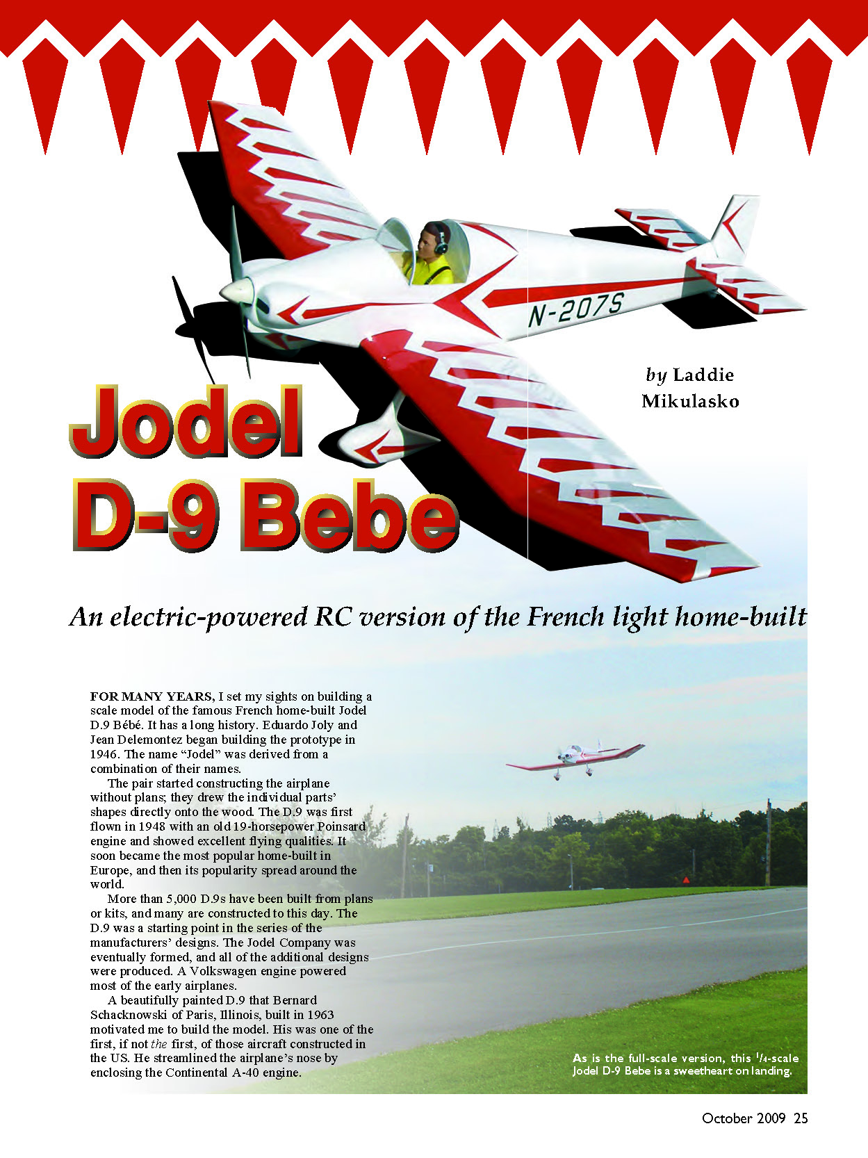
Jodel D-9 Bébé
An electric-powered RC version of the French light home-built
by Laddie Mikulasko
For many years I set my sights on building a scale model of the famous French home-built Jodel D.9 Bébé. It has a long history. Édouard Joly and Jean Delemontez began building the prototype in 1946. The name “Jodel” was derived from a combination of their names. The pair started constructing the airplane without plans; they drew the individual parts’ shapes directly onto the wood. The D.9 was first flown in 1948 with an old 19-horsepower Poinsard engine and showed excellent flying qualities. It soon became the most popular home-built in Europe, and then its popularity spread around the world.
More than 5,000 D.9s have been built from plans or kits, and many are constructed to this day. The D.9 was a starting point in the series of the manufacturers’ designs. The Jodel Company was eventually formed, and all of the additional designs were produced. A Volkswagen engine powered most of the early airplanes.
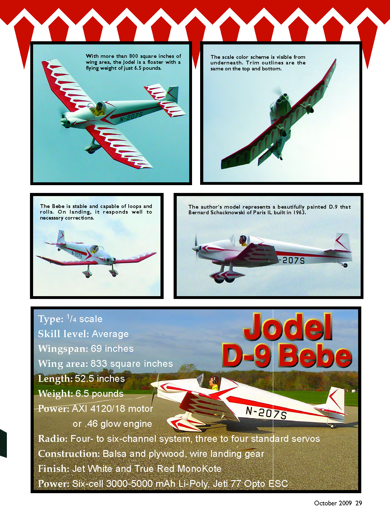
A beautifully painted D.9 that Bernard Schacknowski of Paris, Illinois, built in 1963 motivated me to build the model. His was one of the first, if not the first, of those aircraft constructed in the U.S. He streamlined the airplane’s nose by enclosing the Continental A-40 engine.
I decided to build the model to 1/4 scale. It is of simple construction, using balsa, plywood, and spruce. I powered my version with an electric motor. I knew that the airplane would fly great, and I was not disappointed. Steering on the ground is excellent. When power is applied, the model tracks straight and becomes airborne in no time. Only a bit of down trim on the first flight was required. My D.9 is stable and is capable of loops and rolls. On landing, it responds well to necessary corrections. I am extremely pleased with it.
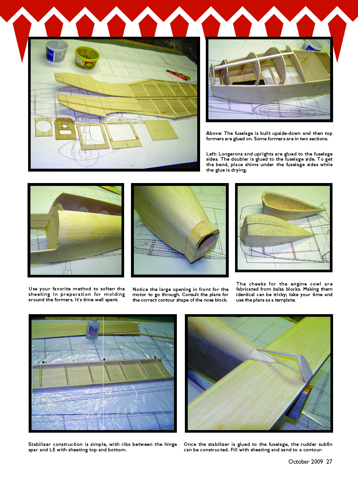
The fuselage is built upside-down and then top formers are glued on. Some formers are in two sections. Longerons and uprights are glued to the fuselage sides. The doubler is glued to the fuselage side. To get the bend, place shims under the fuselage sides while the glue is drying. Use your favorite method to soften the sheeting in preparation for molding around the formers — it’s time well spent. Notice the large opening in front for the motor to go through. Consult the plans for the correct contour shape of the nose block.
The cheeks for the engine cowl are fabricated from balsa blocks. Making them identical can be tricky; take your time and use the plans as a template. Stabilizer construction is simple, with ribs between the hinge spar and leading edge with sheeting top and bottom. Once the stabilizer is glued to the fuselage, the rudder subfin can be constructed. Fill with sheeting and sand to a contour.
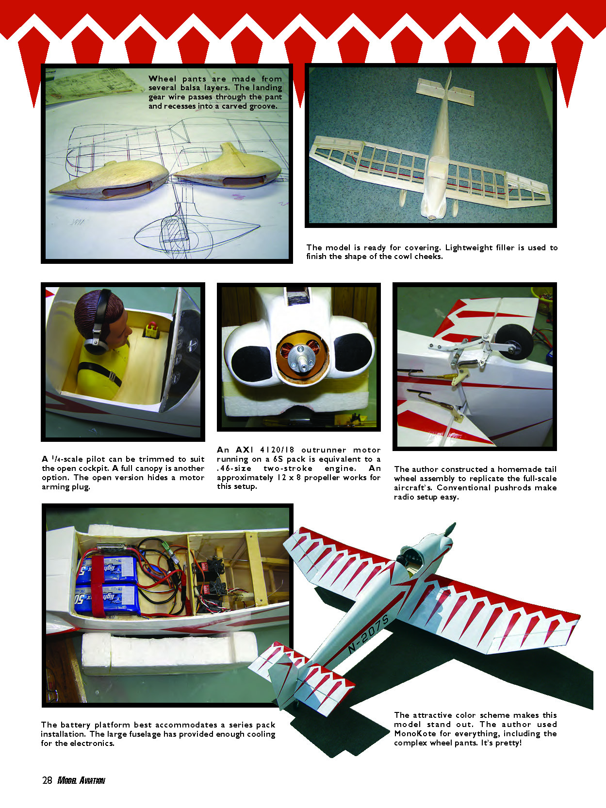
The model is ready for covering. Lightweight filler is used to finish the shape of the cowl cheeks. Wheel pants are made from several balsa layers. The landing gear wire passes through the pant and recesses into a carved groove. I constructed a homemade tail-wheel assembly to replicate the full-scale aircraft’s. Conventional pushrods make radio setup easy. An AXI 4120/18 outrunner motor running on a 6S pack is equivalent to a .46-size two-stroke engine. An approximately 12 x 8 propeller works for this setup. A 1/4-scale pilot can be trimmed to suit the open cockpit. A full canopy is another option. The open version hides a motor arming plug.
The battery platform best accommodates a series-pack installation. The large fuselage has provided enough cooling for the electronics.
The attractive color scheme makes this model stand out. I used MonoKote for everything, including the complex wheel pants — it’s pretty!
Specifications
- Type: 1/4 scale
- Skill level: Average
- Wingspan: 69 inches
- Wing area: 833 square inches
- Length: 52.5 inches
- Weight: 6.5 pounds
- Power: AXI 4120/18 motor or .46 glow engine
- Battery: Six-cell (6S) 3000–5000 mAh Li-Poly
- ESC: Jeti 77 Opto (modified with Castle Creations CC BEC)
- Radio: 4–6 channel system; 3–4 standard servos
- Construction: Balsa, plywood, spruce; wire landing gear
- Finish: Jet White and True Red MonoKote
CONSTRUCTION
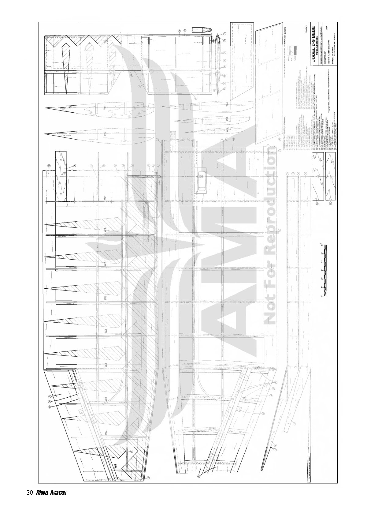
All the pieces on the plans are numbered from 1 to 71, and the ribs and formers are identified with letters.
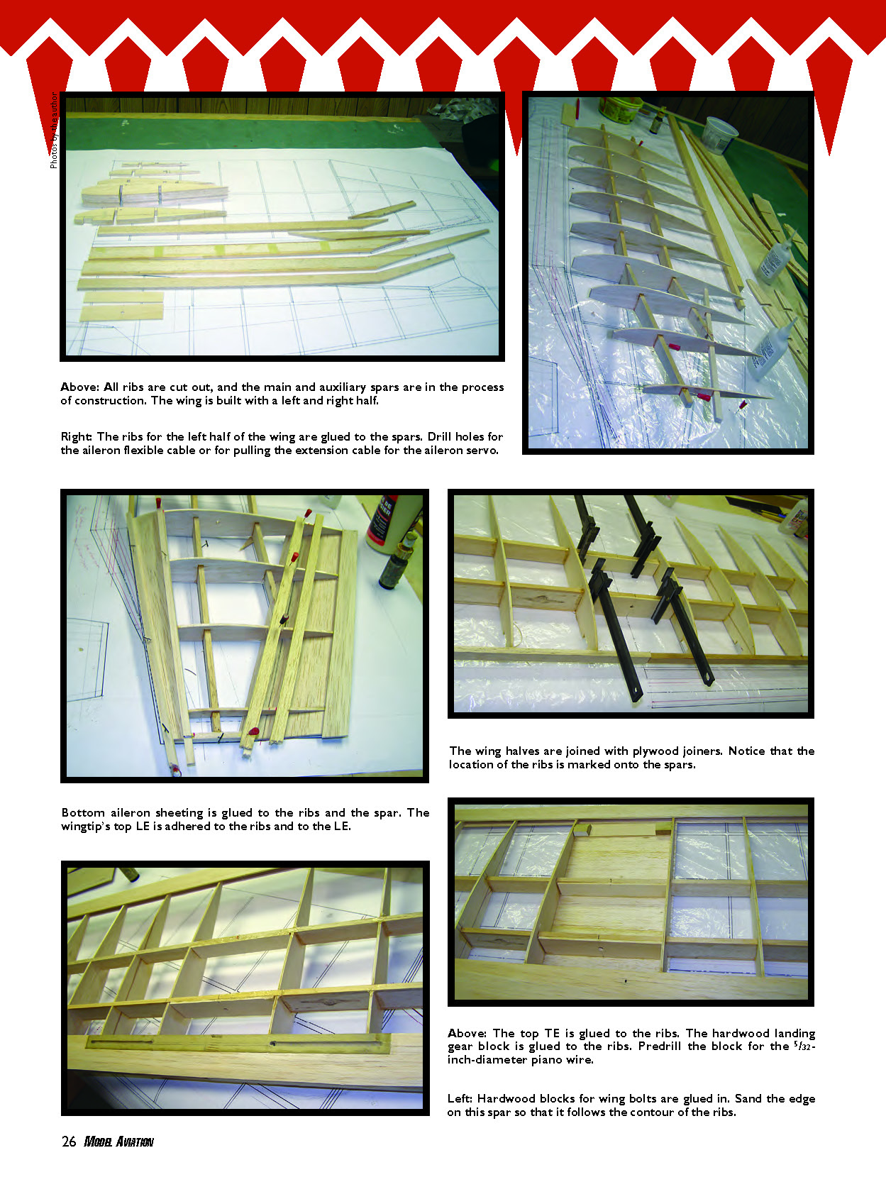
Wing
The wing is built in a left and a right half. Cut all the ribs; do W3, W4, and W5 in one piece.
- Drill holes for the aileron flexible cable or for pulling the extension cable for the aileron servo. Cut out the main spar and rear spar.
- To reinforce the main spar (1), glue the spruce spars (3 and 4) to it. To reinforce the main spar tip (2), adhere the spruce spar (5) to it. Bond the tip spar to the main spar. Glue the tip (7) to the rear spar (6).
- Mark the location of the ribs onto the spars. Slide ribs W1 and W2 onto the spars. Place the 1/8-inch shim under the rear spar. Pin and glue the ribs to the spars. Attach the leading edge (LE) to the ribs.
- Lift the wing and pin the wingtip spars to the building board. Glue ribs W3, W4, and W5 to the spars. Adhere the wingtip LE to the ribs. Bond the 1/4 x 1/4 balsa tip (8) to the spar and to the LE.
- Slide the aileron bottom sheet (16) under the ribs, and slide the wingtip washout guide under that sheet. Glue the ribs to the bottom sheeting (16). Attach the top LE and trailing edge (TE) sheeting to the wingtip.
- Glue the capstrips (22) to ribs W3–W5 where the aileron hinge spar and aileron LE spar will be adhered.
- Separate the aileron from the wingtip by cutting it off at the marked lines drawn on ribs W3–W5. Join the hinge spar (14) to the ribs. Glue the LE (15) to the aileron. Glue the capstrips to the ribs.
- Attach the plywood plate (23) between ribs W3 and W4 to support the aileron horn. Slide the flexible rod for the aileron control into the holes in the ribs.
- Remove the wing from the building board and repeat the same steps to build the other wing half.
- When both halves are completed, pin them to the building board so that the spars touch. Adhere the plywood joiner piece (24) to the main spars and the joiner piece (25) to the rear spars.
- Glue both bottom and top TE sheeting (12) to all W1 and W2 ribs. Adhere the LE spar (10) to ribs W1 and W2 and sand the edge to follow the ribs' contour. Bond the top LE sheeting (13) to all ribs.
- Insert and glue the landing gear hardwood blocks (20) into ribs W1. Attach the bottom LE sheeting to all ribs. Glue in the wing-bolt-support plywood piece (19) to the W1 ribs.
- Adhere the servo tray in the center of the wing. Join sheeting (18) to the W1 ribs. Glue on the LE capstrip (11).
- Sand the wing. Insert and glue in the dowel (21).
Stabilizer and Elevator
- Pin the hinge spar (26) to the building board. Pin and glue all stabilizer ribs to the spar. Bond the LE spar (27) to the ribs. Glue the 1/4 balsa square stick (29) between the hinge spar and the LE at the tips.
- Attach the top sheeting (30). Glue on the bottom sheeting (30). Adhere the LE capstrip (31) to the stabilizer. Sand the stabilizer.
- Cut the elevators (32) from 1/16 balsa. Glue the LE (33) and TE (36) to one side of the elevator sheet (32). Glue in the ribs and 1/4 balsa sheet (34 and 35). Sand that side, flip the elevator, and glue the same items to the other side; sand that side.
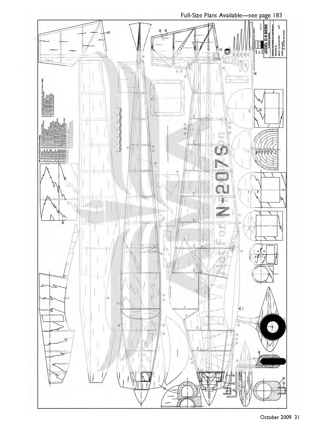
Fuselage and Rudder
- Cut out as many parts as possible; some formers are in two sections. The bottom of some formers is plywood and the top is balsa so that when the fuselage is built upside-down, formers F2, F3, F4, F7, and F8 can touch the building board.
- Former F2 shows the motor mounting holes for the AXI motor I used. You might need to modify the mounting to suit your setup.
- Adhere the doublers (41) to the fuselage side (40). Glue on the longerons (42 and 43) and all uprights (44) to the fuselage sides. Pin the fuselage sides to the building board.
- Insert and glue in formers F4 and F8. Use squares to position everything accurately. Glue in former F8 and all crossbraces (45).
- At the aft end, glue in the rudder-hinge support block (48). Glue in formers F3, F2, and F1.
- Adhere the battery floor (56) and the cockpit floor (57). In the nose section, attach the fuselage bottom (51) and the balsa block (53). Glue the plywood plate (58) between the fuselage sides.
- Flip the fuselage right-side up and glue on formers F2A, F3A, F4A, F5, F7A, F8A, and F9–F14. Adhere the top longerons (46 and 47). Glue the top sheeting (50) over formers F1–F5. Glue on the rear top sheeting (49).
- Join the nose block (54) to the fuselage and sand that structure. Cut the cowl cheeks (55) from balsa blocks, sand them, and adhere them to the fuselage sides. Bond the air scoop (52) to the bottom of the cowl. Fill imperfections with lightweight filler and sand.
- Glue the stabilizer to the fuselage. Glue subfin former F15 to the stabilizer, then attach the balsa sides (65) to this former and to the stabilizer.
- Cut the rudder from 1/16 sheet (59); glue the hinge spar (60) to it. Adhere the LE (61) to the rudder. Glue the rudder-hinge capstrip (62) to the rudder. Glue the rudder bottom sheeting (63) to the rudder and the fin. Sand to shape.
- Glue in ribs R1–R5 and sand that side of the rudder. Flip the rudder and glue in the identical parts to the other side.
- Glue in the plywood plate (63) at the bottom. Glue in a plywood plate (64) to one side of the rudder to hold the rudder control horn.
- Bend 1/16- or 3/32-inch-diameter piano wire to make the tail-wheel leg. Drill the hole in the hinge spar (60) and insert the tail-wheel wire. Wrap a piece of fiberglass around the wire and the rudder spar. Use instant glue to bond the fiberglass to the hinge spar.
Wheel Pants and Landing Gear
- The wheel pants are made from four parts: one pair (66 and 67) includes the shape with the leg; the second pair (66 and 67) has the shape without the legs.
- Cut the wheel pant shapes. In the part (66), cut out the wheel well. Glue two (66) parts together and adhere parts (67) to both sides of the (66) parts.
- Drill a hole for the landing gear axle. Sand the wheel pants to the shape shown on the drawing. At the back of the wheel pants part (67) cowl, cut and make the groove for accepting the landing gear wire (69).
- Bend and cut the 5/32-inch-diameter piano wire to the proper shape and length. Insert the wire into the groove in the wheel pants for a trial fit. If satisfied, remove the wire. The landing gear wire will be permanently installed after the wheel pants are finish-covered.
Final Assembly
- Cover the model with your favorite material; I used MonoKote.
- Install the hinges, controls, and motor. I mounted my AXI with four Allen-head screws that hold it in from the back, using a long-handle screwdriver.
- When installing the motor, the speed controller is already connected to it. I used a Jeti 77 Opto ESC, modified with a Castle Creations CC BEC.
- For safety, install an arming plug in series with the battery that is accessible from the cockpit. Without this plug, there is no power to the speed controller and motor. I urge you to use this setup for the D.9 and all other larger models you have.
I reviewed this model's flight at the beginning of the article.
Good luck! MA
Laddie Mikulasko [email protected]
Sources
- The Jodel Company — www.jodel.com
- Hobby Lobby International — (866) 512-1444, www.hobby-lobby.com
- Top Flite MonoKote — (217) 398-8970, www.monokote.com
- Castle Creations — (913) 390-6939, www.castlecreations.com
Transcribed from original scans by AI. Minor OCR errors may remain.

