
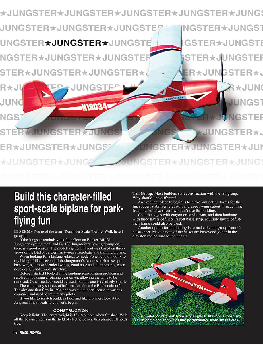
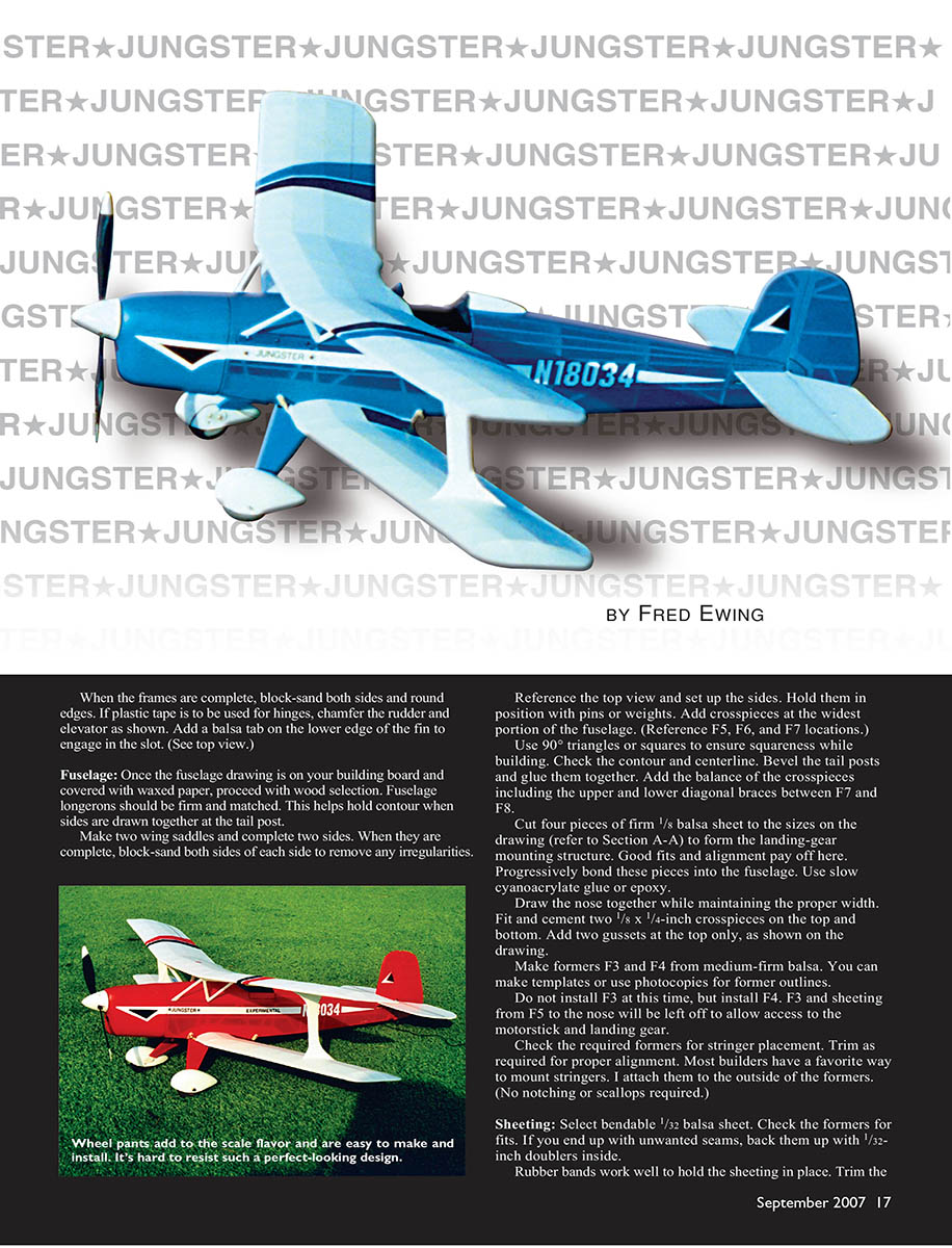
Jungster
Fred Ewing
Build this character-filled sport-scale biplane for park-flying fun
IT SEEMS I've used the term "Reminder Scale" before. Well, here I go again.
If the Jungster reminds you of the German Bücker Bu.131 Jungmann (young man) and Bu.133 Jungmeister (young champion), there is a good reason. The model's general layout was based on three-views of the Bu.131: a German two-seat aerobatic and training biplane.
When looking for a biplane subject to model (one I could modify to my liking), I liked several of the Jungmann's features such as swept-back wings, almost identical wings, good nose and tail moments, clean nose design, and simple structure.
Before I started I looked at the landing-gear-position problem and resolved it by using a rotating gear cover, allowing the wing to be removed. Other methods could be used, but this one is relatively simple.
There are many sources of information about the Bücker aircraft. The airplane first flew in 1934 and was built under license in various countries and used to train many pilots.
If you like to scratch build, as I do, and like biplanes, look at the Jungster. If it appeals to you, let's begin.
CONSTRUCTION
Keep it light! The target weight is 13-16 ounces when finished. With all the advancements in the field of electric power, this phrase still holds true.
Tail Group: Most builders start construction with the tail group. Why should I be different?
An excellent place to begin is to make laminating forms for the fin, rudder, stabilizer, elevator, and upper wing cutout. I made mine from old 1/8 balsa sheet I wouldn't use for building.
Coat the edges with crayon or candle wax, and then laminate with three layers of 1/16 x 1/8 soft balsa strip. Multiple layers of 1/32-inch frame could also be used.
Another option for laminating is to make the tail group from 1/8 balsa sheet. Make a note of the 1/8 square basswood joiner in the elevator and be sure to include it!
Jungster
By Fred Ewing
When the frames are complete, block-sand both sides and round edges. If plastic tape is to be used for hinges, chamfer the rudder and elevator as shown. Add a balsa tab on the lower edge of the fin to engage in the slot. (See top view.)
Fuselage: Once the fuselage drawing is on your building board and covered with waxed paper, proceed with wood selection. Fuselage longerons should be firm and matched. This helps hold contour when sides are drawn together at the tail post.
Make two wing saddles and complete two sides. When they are complete, block-sand both sides of each side to remove any irregularities.
Reference the top view and set up the sides. Hold them in position with pins or weights. Add crosspieces at the widest portion of the fuselage. (Reference F5, F6, and F7 locations.)
Use 90° triangles or squares to ensure squareness while building. Check the contour and centerline. Bevel the tail posts and glue them together. Add the balance of the crosspieces including the upper and lower diagonal braces between F7 and F8.
Cut four pieces of firm 1/8" balsa sheet to the sizes on the drawing (refer to Section A-A) to form the landing-gear mounting structure. Good fits and alignment pay off here. Progressively bond these pieces into the fuselage. Use slow cyanoacrylate glue or epoxy.
Draw the nose together while maintaining the proper width. Fit and cement two 1/8 x 1/4-inch crosspieces on the top and bottom. Add two gussets at the top only, as shown on the drawing.
Make formers F3 and F4 from medium-firm balsa. You can make templates or use photocopies for former outlines.
Do not install F3 at this time, but install F4. F5 and sheeting from F5 to the nose will be left off to allow access to the motorstick and landing gear.
Check the required formers for stringer placement. Trim as required for proper alignment. Most builders have a favorite way to mount stringers. I attach them to the outside of the formers. (No notching or scallops required.)
Sheeting: Select bendable 1/32" balsa sheet. Check the formers for fits. If you end up with unwanted seams, back them up with 1/32-inch doublers inside.
Rubber bands work well to hold the sheeting in place. Trim the sheeting even with the fuselage after it is cemented. Be careful not to warp the fuselage.
Center the wing on the fuselage and fit in place. The wing saddle areas may require a slight sanding to get the proper wing incidence. Once happy with the fit, glue the wing saddle sheeting in place.
Landing gear: Bend gear wire to drawing and bind to the mounting blocks with music wire clamps or use epoxy and fiberglass tape for reinforcement.
Tailgroup: Install the fin, rudder, stabilizer, and elevator. Make sure hinges are aligned and the control surfaces move freely. Use control horns and pushrods per the radio installation drawing.
Covering and finishing: I used lightweight iron-on film. Apply film according to manufacturer's instructions. Markings can be painted or cut from film. Balance the airplane at the point shown on the plan by adding weight to the nose or tail as required. Test fly gently; make small trims until the airplane handles well.
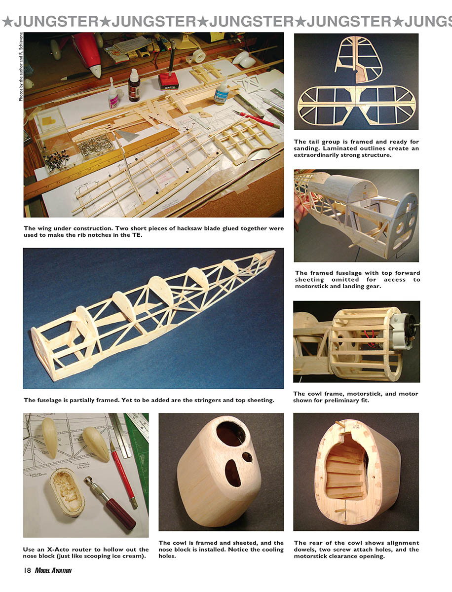
The wing under construction. Two short pieces of hacksaw blade glued together were used to make the rib notches in the TE.
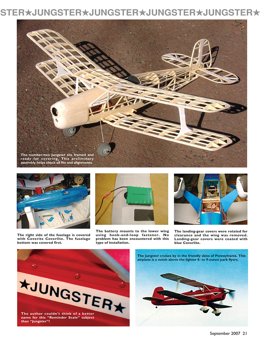
The tail group is framed and ready for sanding. Laminated outlines create an extraordinarily strong structure.
The framed fuselage with top forward sheeting omitted for access to motorstick and landing gear.
The fuselage is partially framed. Yet to be added are the stringers and top sheeting.
The cowl frame, motorstick, and motor shown for preliminary fit.
Use an X-Acto router to hollow out the nose block (just like scooping ice cream).
The cowl is framed and sheeted, and the nose block is installed. Notice the cooling holes.
The rear of the cowl shows alignment dowels, two screw attach holes, and the motorstick clearance opening.
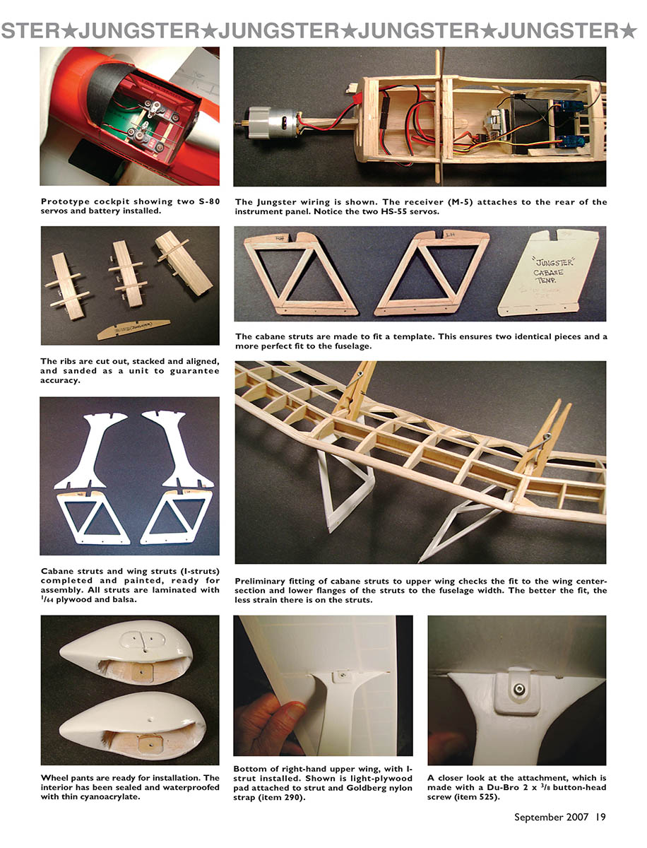
Prototype cockpit showing two S-80 servos and battery installed.
The Jungster wiring is shown. The receiver (M-5) attaches to the rear of the instrument panel. Notice the two HS-55 servos.
The ribs are cut out, stacked and aligned, and sanded as a unit to guarantee accuracy.
The cabane struts are made to fit a template. This ensures two identical pieces and a more perfect fit to the fuselage.
Cabane struts and wing struts (I-struts) completed and painted, ready for assembly. All struts are laminated with 1/64 plywood and balsa.
Preliminary fitting of cabane struts to upper wing checks the fit to the wing centersection and lower flanges of the struts to the fuselage width. The better the fit, the less strain there is on the struts.
Wheel pants are ready for installation. The interior has been sealed and waterproofed with thin cyanoacrylate.
Bottom of right-hand upper wing, with I-strut installed. Shown is light-plywood pad attached to strut and Goldberg nylon strap (item 290).
A closer look at the attachment, which is made with a Du-Bro 2 x 3/8 button-head screw (item 525).
Jungster
Fred Ewing
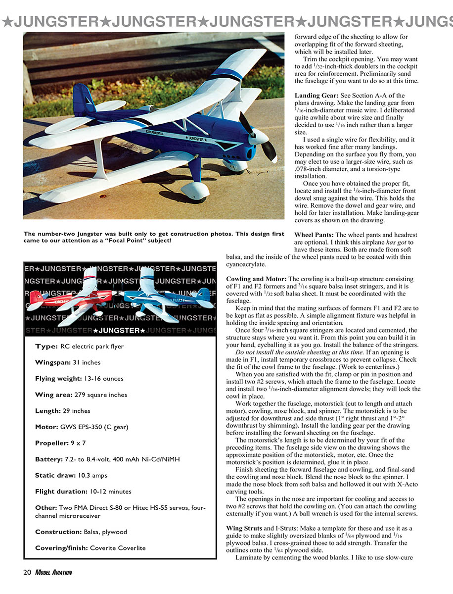
The number-two Jungster was built only to get construction photos. This design first came to our attention as a "Focal Point" subject!
Type: RC electric park flyer
- Wingspan: 31 inches
- Flying weight: 13-16 ounces
- Wing area: 279 square inches
- Length: 29 inches
- Motor: GWS EPS-350 (C gear)
- Propeller: 9 x 7
- Battery: 7.2- to 8.4-volt, 400 mAh Ni-Cd/NiMH
- Static draw: 10.3 amps
- Flight duration: 10-12 minutes
- Other: Two FMA Direct S-80 or Hitec HS-55 servos, four-channel microreceiver
- Construction: Balsa, plywood
- Covering/finish: Coverite Coverlite
forward edge of the sheeting to allow for overlapping fit of the forward sheeting, which will be installed later.
Trim the cockpit opening. You may want to add 1/32-inch-thick doublers in the cockpit area for reinforcement. Preliminarily sand the fuselage if you want to do so at this time.
Landing Gear: See Section A-A of the plans drawing. Make the landing gear from 1/16-inch-diameter music wire. I deliberated quite awhile about wire size and finally decided to use 1/16 inch rather than a larger size.
I used a single wire for flexibility, and it has worked fine after many landings. Depending on the surface you fly from, you may elect to use a larger-size wire, such as .078-inch diameter, and a torsion-type installation.
Once you have obtained the proper fit, locate and install the 1/8-inch-diameter front dowel snug against the wire. This holds the wire. Remove the dowel and gear wire, and hold for later installation. Make landing-gear covers as shown on the drawing.
Wheel Pants: The wheel pants and headrest are optional. I think this airplane has got to have these items. Both are made from soft balsa, and the inside of the wheel pants need to be coated with thin cyanoacrylate.
Cowling and Motor: The cowling is a built-up structure consisting of F1 and F2 formers and 3/16 square balsa inset stringers, and it is covered with 1/32 soft balsa sheet. It must be coordinated with the fuselage.
Keep in mind that the mating surfaces of formers F1 and F2 are to be kept as flat as possible. A simple alignment fixture was helpful in holding the inside spacings and orientation.
Once four 3/16-inch square stringers are located and cemented, the structure stays where you want it. From this point you can build it in your hand, eyeballing it as you go. Install the balance of the stringers.
Do not install the outside sheeting at this time. If an opening is made in F1, install temporary crossbraces to prevent collapse. Check the fit of the cowl frame to the fuselage. (Work to centerlines.)
When you are satisfied with the fit, clamp or pin in position and install two #2 screws, which attach the frame to the fuselage. Locate and install two 1/16-inch-diameter alignment dowels; they will lock the cowl in place.
Work together the fuselage, motorstick (cut to length and attach motor), cowling, nose block, and spinner. The motorstick is to be adjusted for downthrust and side thrust (1° right thrust and 1°-2° downthrust by shimming). Install the landing gear per the drawing before installing the forward sheeting on the fuselage.
The motorstick's length is to be determined by your fit of the preceding items. The fuselage side view on the drawing shows the approximate position of the motorstick, motor, etc. Once the motorstick's position is determined, glue it in place.
Finish sheeting the forward fuselage and cowling, and final-sand the cowling and nose block. Blend the nose block to the spinner. I made the nose block from soft balsa and hollowed it out with X-Acto carving tools.
The openings in the nose are important for cooling and access to two #2 screws that hold the cowling on. (You can attach the cowling externally if you want.) A ball wrench is used for the internal screws.
Wing Struts and I-Struts: Make a template for these and use it as a guide to make slightly oversized blanks of 1/64 plywood and 1/16 plywood balsa. I cross-grained those to add strength. Transfer the outlines onto the 1/64 plywood side.
Laminate by cementing the wood blanks. I like to use slow-cure cyanoacrylate glue for this. Place the structure on a flat surface, apply weights, and allow it to cure. Carefully profile the perimeter using your scroll saw. Omit notches at this time.
Finish by hand-sanding to airfoil shape. Mark inside at the top left-hand and right-hand side. Apply thin cyanoacrylate to the ends in the area of the notches. Carefully and accurately cut the notches to match the template.
Cabane Struts: (See sections A-A and B-B on the drawing.) A template can be used or build two frames on the plans (Section B-B). Build two balsa frames from 1/16 x 1/4-inch balsa strip. Cut two 1/64 plywood blanks. Reference the blank-size template shown on the drawing. Cement the frames to these.
A left- and right-hand side is required, so put the plywood on the inside. Cut plywood openings and then finish-sand the profile to an airfoil shape. The top and bottom flanges remain only plywood.
Lightly score the top and bottom at the bend lines. Make sure there is a right and left hand when doing this. Carefully bend and crack just enough to match the end view in Section A-A. When you are satisfied with the bends, apply thin cyanoacrylate to the resulting crack.
Before final-gluing, coordinate the cabane struts to the upper wing and your fuselage width for a proper fit per the assembly sequence. When dried, cut and fit reinforcing tape over the bend-line joint.
Apply thin cyanoacrylate to this tape and final-trim. Lightly coat the tape with epoxy. Lay out and open six small pilot holes in the lower plywood edge for #2 screw attachment to the fuselage.
Wings: At this point I would say you are definitely committed to this project, so let’s build the wings.
Put the wing plans on your building board and cover with waxed paper. Make a rib template using your favorite method; I like to use 1/16 plywood for this. You can add nose ribs (false ribs) if you want.
Cut all ribs, stack them, pin them, and sand them for uniformity. Progressively assemble the wings, making center-sections first.
Notice that the W2 ribs at I-strut locations are tilted slightly so the struts are 90° when installed. Make a 7° dihedral gauge per the drawing and tilt the root ribs when installing. Make and cement all gussets. I beefed up the upper center-section at the opening because people pick up the airplane as if that were a handhold.
Check the fits of the wing panels to their respective center-sections. Block-sand them for a good fit. Preliminarily shape and sand all parts before joining. Set up and epoxy the outer wing panels to the center-sections. Clamp and allow to cure.
Make the four dihedral braces using 1/32 plywood. Make openings in ribs W2 for the braces. Score, crack, and check them for fit.
Apply nylon tape with thin cyanoacrylate to the joint and coat lightly with epoxy. Epoxy in the wings and install the shear webs. Blend and taper the wingtips as shown. Finish-sand the completed wings.
Assembly: When the wings are completed, check the fit of the lower wing to the fuselage wing saddle. When you are satisfied with the fit, rubber-band the wing in place. (Use #32 and #33 bands, and temporarily install wing dowels.)
Make an access hatch. An extra wing rubber band or hand holds the hatch in place.
Check the cabane struts and I-struts for proper fits. Refer to drawing Section A-A and B-B. Temporarily clamp the cabane struts to the upper wing as shown in Section A-A and B-B. Position the I-struts on the wing (in slots), ensuring that they fit and nest on the spars. Place the upper wing on the I-struts.
Check the cabane struts for fit to the fuselage. You can epoxy the struts into the wing at this point if all looks well or you can do it later, after you have covered the bottom of the upper wing. By doing it this way you have access for clamping and simplify covering.
The cabane struts are the means of setting the distance from the fuselage to the center-section and 2° positive incidence of the upper wing. The lower wing should be 1° positive, so take your time with this operation.
Check the gap between the upper and lower wings. Refer to the drawing for I-strut spacing. Cement the I-struts to the wing and fuselage. Install any necessary fillets and fairings.
Landing Gear: Cut the gear wire per the drawing and fit to the fuselage. Add balsa fairings for the gear as shown. Mount the wheels and check alignment. Make sure the gear is square and centered.
Tail Surfaces: Build the stabilizer and fin per the plans. Dry-fit all tail parts to the fuselage and check alignment. When satisfied, epoxy the parts into position and add any necessary fillets. Sand and true the tail surfaces.
Covering: I covered the model with Coverite Coverlite. Use the covering method you prefer. I suggest covering the fuselage sides first, then the bottom, and finally the top. Cover the wings next, taking care to keep the airfoils true. Apply trim and markings as desired.
Final Installation: Install the control surfaces, hinges, control horns, and linkages. Balance the airplane per the plans. Check the operation of the radio gear and all control throws. Make any final adjustments to incidence and control settings.
Flying: For initial flights, use gentle conditions and keep the flights short while trimming. The Jungster is stable and predictable; make small control inputs while establishing trim. Once trimmed, you will find the Jungster to be a pleasant and capable sport-scale ship.
detail. Strut attachment to the upper wing is to be accomplished after bonding the struts to the lower wings. Once the gap between the wings is set, locate and epoxy nylon straps to the wing rib as shown. Drill pilot holes and install #2 x 3/8-inch button-head screws.
From the fuselage to the bottom of the center-section on the prototype, the forward gap is approximately 1 inch and the rear is 3/4 inch.
Once you are satisfied, install the cabane struts with #2 screws per the drawing. On the prototype model I set the alignment and incidence without making a fixture. No washout was required in the wingtips, but a little can't hurt.
Once the airplane's preliminary assembly is completed, you can finish miscellaneous details such as servo rails, fitting servos, making pushrods, etc. I used 1/8-square firm balsa pushrods with short 1/32-inch-diameter wire ends for the prototype. I used Du-Bro Mini E/Z Connectors (catalog item 845) and Micro E/Z Links (catalog item 849) at elevator and rudder.
Rout the wiring and the receiver. The ESC is allowed to dangle free for cooling. Use Velcro to attach the receiver to the rear of the instrument panel. Prepare for covering, removing items that would interfere.
On the prototype airplane I used Coverite Coverlite, which is strong and extremely light. I used Balsaloc adhesive. Other adhesives can be used per Coverite instructions. Color, covering, and trim are your choice because this is not a scale airplane.
After covering, epoxy the I-struts into the lower wing. For striping I used Coverite trim sheet. The trim on the wings was cut from Coverite. I applied Balsaloc to the inside with a warm iron. I sprayed the wheel pants with Testors enamel and painted the struts with Testors acrylic enamel.
Use the dull side of black Coverlite for the wing walk and over the instrument panel. Make the windshield from .010-.015 clear plastic and attach it with RC/56 adhesive or equivalent. The 1/4-inch letters are stick-on vinyl from an office-supply store.
When complete, balance the airplane where shown on the drawing (at the upper wingtips). The prototype Jungster turned out slightly nose-heavy, so I gradually moved the battery back to where it is shown on the plans.
Add tail weight if necessary. I added 1/4 ounce of weight to the prototype and number-two Jungster inside the fuselage at the tail post.
I am currently flying it with a seven-cell, 8.4-volt, AAA 750 mAh NiMH GWS battery pack. Duration has consistently been 10-12 minutes.
I have yet to try Li-Poly batteries in this airplane, but I probably will eventually. I realize that there is much to choose from equipmentwise, but I know what works in this airplane right now.
Flying: When I decided to proceed in building this airplane, I set my weight goal in the 13- to 16-ounce range. I feel it would handle slightly more wind than those airplanes in the 8- to 9-ounce range. I also based it on using the GWS EPS-350C motor. I can say my objectives have been met.
The Jungster is a three-channel fun-flyer that takes off nicely and will do nice loops, spins, rudder rolls, etc. with control throws shown on drawing. I am using a GWS propeller, item EP9070.
Additional drag is involved with a biplane, so on landing approach with slight power and cut just before flaring out. As will typical biplanes, if slowed too much the Jungster will stall and drop a wing.
I usually fly from a hard surface or a baseball diamond's packed sand. Leave the wheel pants off if you are flying from grass, unless it is exceptionally short. Hand launching is easy.
I hope you have enjoyed scratch-building this model. I hope you have fun flying it, and good luck. I would be glad to hear from Jungster builders and fliers.
Fred J. Ewing The Chestnut House 130 N. Second St. Apt. B-3 Souderton PA 18964
Sources:
Jane's Pocket Book of Light Aircraft John W.R. Taylor
Civil Aircraft of the World John W.R. Taylor and Gordon Swanborough
Profile Publications No. 222
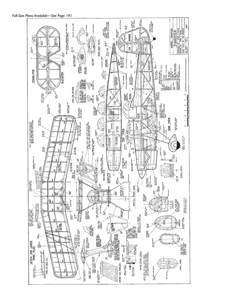
Full-Size Plans Available—See Page 191
Transcribed from original scans by AI. Minor OCR errors may remain.

