
KANDU
by Dale Singleton
If you want a great sport flier, this model can do it
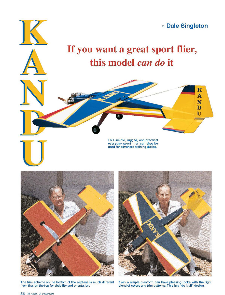
This simple, rugged, and practical everyday sport flier can also be used for advanced training duties.
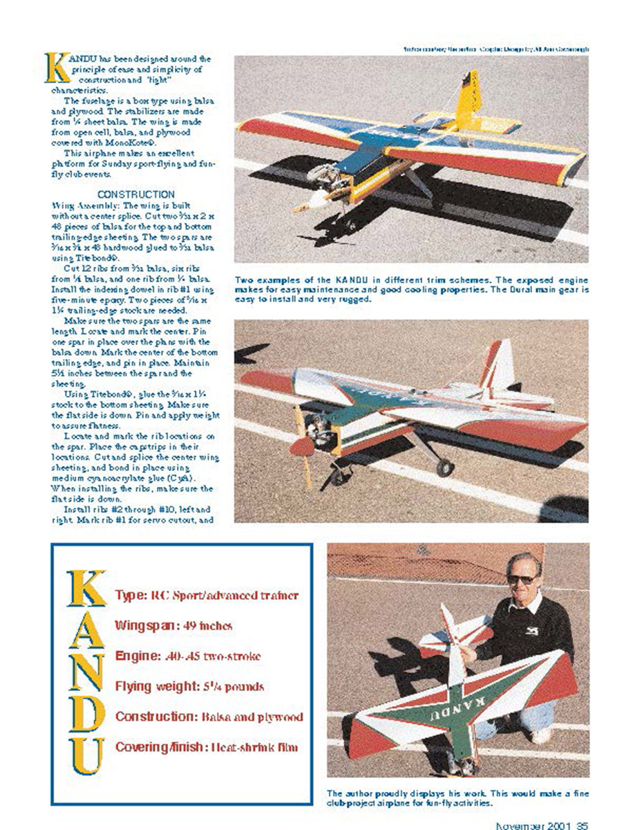
The trim scheme on the bottom of the airplane is much different from that on the top for visibility and orientation.
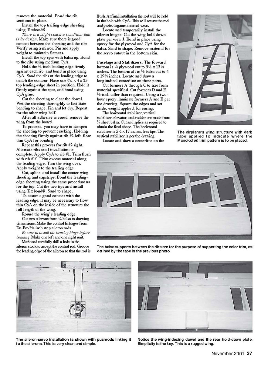
Even a simple platform can have pleasing looks with the right blend of colors and trim patterns. This is a "do it all" design.
CONSTRUCTION
Wing Assembly: The wing is built without a center splice. Cut two 3/8 x 2 x 48 pieces of balsa for the top and bottom trailing-edge sheeting. The two spars are 3/16 x 3/4 x 48 hardwood glued to 3/32 balsa using Titebond®.
Cut 12 ribs from 3/32 balsa, six ribs from 1/8 balsa, and one rib from 1/8 balsa. Install the indexing dowel in rib #11 using five-minute epoxy. Two pieces of 1/16 x 1 1/2 trailing-edge stock are needed.
Make sure the two spars are the same length. Locate and mark the center. Pin one spar in place over the plan with the balsa down. Mark the center of the bottom trailing edge, and pin in place. Maintain 5/64 inch between the spars and the sheeting.
Using Titebond®, glue the 3/16 x 1 1/2 stock to the bottom sheeting. Make sure the flat side is down. Pin and apply weight to assure flatness.
Locate and mark the rib locations on the spar. Place the cap strips in their locations. Cut and splice the center wing sheeting, and bond in place using medium cyanoacrylate glue (CA). When installing the ribs, make sure the flat side is down.
Install rib #2 through #10, left and right. Mark rib #11 for servo cutout, and remove the material. Bond the rib sections in place.
Install the top trailing-edge sheeting using Titebond®.
There is a slight concave condition that is in the design. Make sure there is good contact between the sheeting and the ribs. Verify using a mirror. Pin and apply weight to maintain flatness.
Install the top spar with balsa up. Bond to the ribs using medium CyA.
Hold the 1/4-inch leading edge firmly against each rib, and bond in place using CyA. Sand the ribs at the leading edge to match the contour. Place one 3/32 x 4 x 25 top leading-edge sheet in position. Hold it firmly against the spar, and bond using CyA glue.
Cut the sheeting to clear the dowel. Wet the sheeting thoroughly to facilitate bending to shape. Pin and let dry. Repeat for the other wing half.
After all adhesive is cured, remove the wing from the board.
To proceed, you may have to dampen the sheeting to prevent cracking. Holding the sheeting firmly against rib #2 left, flow thin CyA for bonding.
Repeat this process for rib #2 right. Alternate ribs until installation is complete. Apply CyA to rib #1. Trim flush with rib #10. Trim excess material along the leading edge. Turn the wing over. Apply weight to the trailing edge.
Cut, splice, and install the center wing sheeting and capstrips. Bond the leading-edge sheeting using the same procedure as for the top. Cut the two tips and install using Titebond®. Sand to shape.
To assure a good contact with the leading edge, it may be necessary to flow thin CyA on the inside of the structure the full length of the wing.
Round the wing's leading edge.
Cut two ailerons from 1/8 balsa to drawing dimensions. Make the control linkages from Du-Bro 3/32-inch strip aileron rods.
Be sure to install the bearing hinge before bending. Make one left and one right unit.
Mark and carefully drill a hole in the aileron stock to accept the control rod. Groove the leading edge of the aileron so that the rod is flush. At final installation the rod will be held in the hole with CyA. This will secure the rod and protect against internal wear.
Locate and temporarily install the aileron hinges. Cut the wing hold-down plate per view J. Bond in place using epoxy for the plywood and CyA for the balsa. Sand to shape. Remove material for the servo cutout in the bottom skin.
Fuselage and Stabilizers: The forward bottom is 1/8 plywood cut to 3 1/2 x 13 1/4 inches. The bottom aft is 1/8 balsa cut to 4 x 19 1/4 inches. Locate and draw a longitudinal centerline on these parts.
Cut formers A through C to size from material specified. Cut formers D and E 1/8-inch taller than required. Using a two-hour epoxy, laminate formers A and B per the drawing. Square the edges and set aside, weight applied, for curing.
The horizontal stabilizer, vertical stabilizer, elevator, and rudder are made from 3/32 sheet balsa. Cut and splice as required to obtain the final shape. The horizontal stabilizer is 5 1/2 x 17 inches, less tips. The vertical stabilizer is per the drawing.
Locate and draw a centerline on the horizontal stabilizer. Apply a bead of medium CyA on the bottom edge of the vertical stabilizer. Center on the line, and make sure it is 90° to surface.
Install 3/8" triangle stock as per the drawing. Place the bottom fore and aft and stabilizer assembly on the board. Align the centerlines and secure in place. Apply weight to both sides of the horizontal stabilizer to assure flatness.
Apply two-hour epoxy to the bottom edge of the firewall. Center on the line on the bottom section. Be sure that it is vertical and square to the bottom. This airplane has zero right thrust and downthrust.
Locate and install the remaining bulkheads using Pacer® medium CyA or Zap-A-Gap®. Using two-hour epoxy, install the dual-purpose 1/4 x 2 3/8 x 3 1/2 plywood main gear/splice doubler per drawing.
Install the shim between the vertical stabilizer and the fuselage bottom at the horizontal stabilizer's leading edge.
The side panels are 3/16 balsa. Cut two pieces from 4 x 48 stock to 38 1/2 inches. The pieces should be of equal hardness. The bottom edge must be straight. Trim as necessary.
Make sure the forward end is square and flush with the firewall. You must remove 1/8 inch of material from the 5 1/2-inch dimension in contact with the horizontal stabilizer. Assure that there is good contact for the full 38-inch length. Mark and trim the material from the top between formers A, B, C, and the fuselage end.
Place one panel in position, flush with the firewall forward edge. Flow a bead of medium CyA along the edge of former B. Hold the panel firmly against the bottom and bulkhead B. Repeat this process for the remaining bulkheads and the other side.
Bond the fuselage bottom between formers B and C using medium CyA. Add the 10-inch piece of 3/8" triangle stock using CyA. Repeat this process for the other side.
Holding the side panels firmly against the bottom, flow thin CyA along the full interior between former B and the horizontal leading edge, both sides. Trim the excess material from the bottom aft section. Apply two-hour epoxy to the sides of the firewall. Secure the side panels, and set aside for curing.
After the firewall has cured, install all of the triangle stock indicated on the drawing from firewall to former E, using CyA glue. Rout the centers of bulkheads C through E for control-rod installation.
Cut the control-rod exits in the fuselage sides per the drawing. Assemble the servo rails per view H on the drawing. Install them with two-hour epoxy.
Cut the wing saddle using the template shown. Cut two hardwood blocks for the wing-mounting bolts, and bond them in with two-hour epoxy. Drill the holes and install the blind nuts. Install the plywood wing hold-down per view J. place using epoxy. Cut two saddle doublers from 3/16 balsa, and install per drawing using Titebond®.
The hatch cover is made from 3/8 balsa, trimmed to fit the fuselage. Using CyA, bond a piece of 1-inch triangle stock, 3½ inches long, to the aft end. Bevel to get a good fit to former B. Do not trim the top edge at this time.
Install the Carl Goldberg nose-gear bearing. Using the bearing as a guide, drill a 5/32-inch-diameter hole through the fuselage bottom for the nose-gear strut. Cut one piece of hardwood for hatch attachment per the drawing. Bond it in place with epoxy.
After curing, put the cover in place and drill for the attach screw of your choice. Block up the hatch using 1/16 scrap balsa at the fore and aft end. Hold in place and drill two 1/8-inch-diameter holes through former B into—but not through—the hatch triangle stock. Install the 1/8-inch-diameter dowel per drawing using CyA. Trim flush with aft side of former B.
Install the hatch, and sand the top flush with the top of former B.
Put the Sullivan Gold-N-Rod #503 red sleeves for elevator and rudder control in position. Extend the sleeves ½ inch outside the fuselage. Drill and locate the supports at formers C, D, and E per the drawing.
Before bonding, install the yellow rod to make sure there is no binding throughout travel. Bond the supports using CyA. Apply CyA to the red sleeve to prevent movement. Cut or sand the red sleeve material that protrudes from the fuselage slots flush to the side panel.
The fuselage top is 1/8 x 4 x 23 balsa. Cut a 1/4-inch slot in the aft end to accommodate the vertical stabilizer. Trim the excess material from formers D and E flush to the side panel. Apply Titebond® to these bulkheads.
Slide the top section into position, flush with the aft end. Holding the top firmly against the side panel, flow thin CyA along the joint from former C to the end of the fuselage. Repeat for the other side.
Apply CyA between the top and the vertical stabilizer. Wipe off excess adhesive. Set the fuselage aside with weight applied at formers D and E until the Titebond® sets. Trim the top section flush with the forward side of former C.
Locate and temporarily install the hinges for the rudder and elevator. Prepare the control surfaces per views F and G.
Install the wing in the fuselage. Center the trailing edge. While firmly holding the wing, drill and tap one mounting hole for a 1/4-20 bolt. Install the bolt to secure the wing in place, and repeat for the other hole.
Reinstall the wing. Cut scrap balsa for the forward fairing at bulkhead C. Sand to shape. Locate the main-gear-strut position. Drill four holes and mount the gear. Drill and mount the engine of your choice.
Round all edges on the fuselage, wing, and control surfaces. Install the hinges as located. Drill a .090-inch hole through the balsa and the hinge. Put a round toothpick in the hole, and apply CyA. Sand flush with the surface.
Rigging: Set the ailerons centered on the wing chord line. The amount of travel will depend on the pilot's skill. Start at 3/8 inch of travel. Elevator travel is adequate for general flying at 1/2 inch. The nose wheel needs 1/4 inch of travel.
I am a member of the Arizona Model Aviators. There are currently four of these airplanes flying at our field.
If you have questions about the building process or would like a detailed instruction booklet for constructing this airplane, please contact me at <REDACTED>.
Dale E. Singleton <REDACTED>
See pages 171 and 172 for KANDU plans and three-view.
Transcribed from original scans by AI. Minor OCR errors may remain.

