
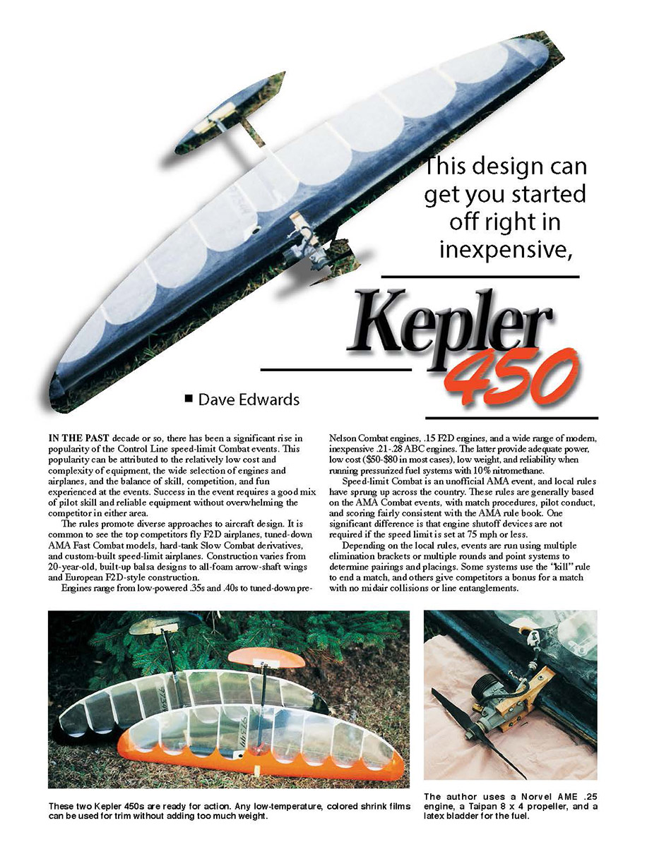
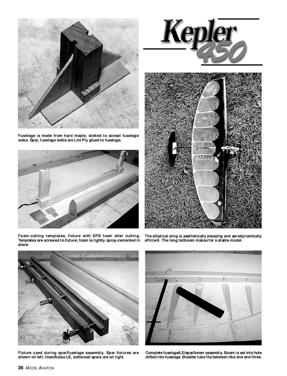
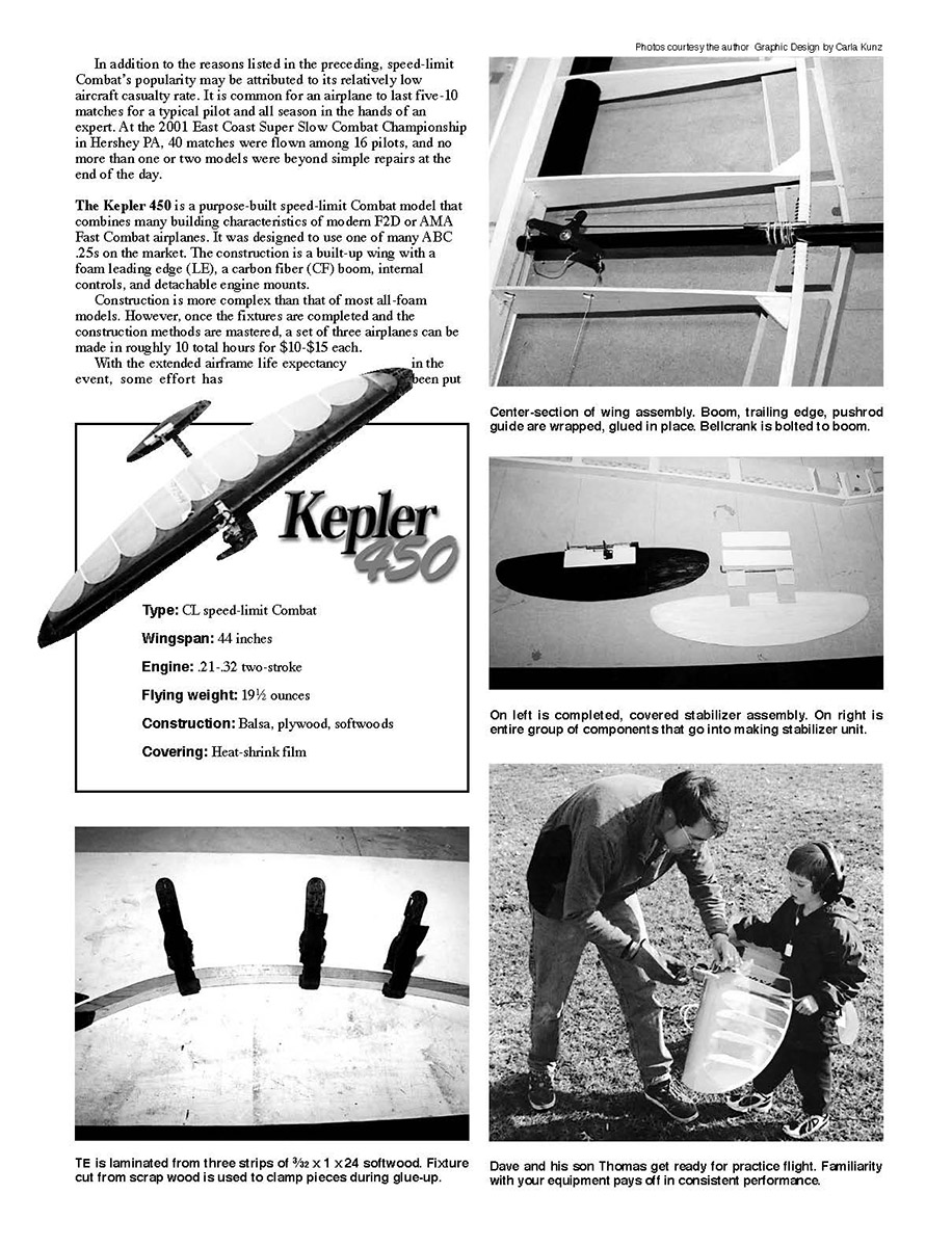
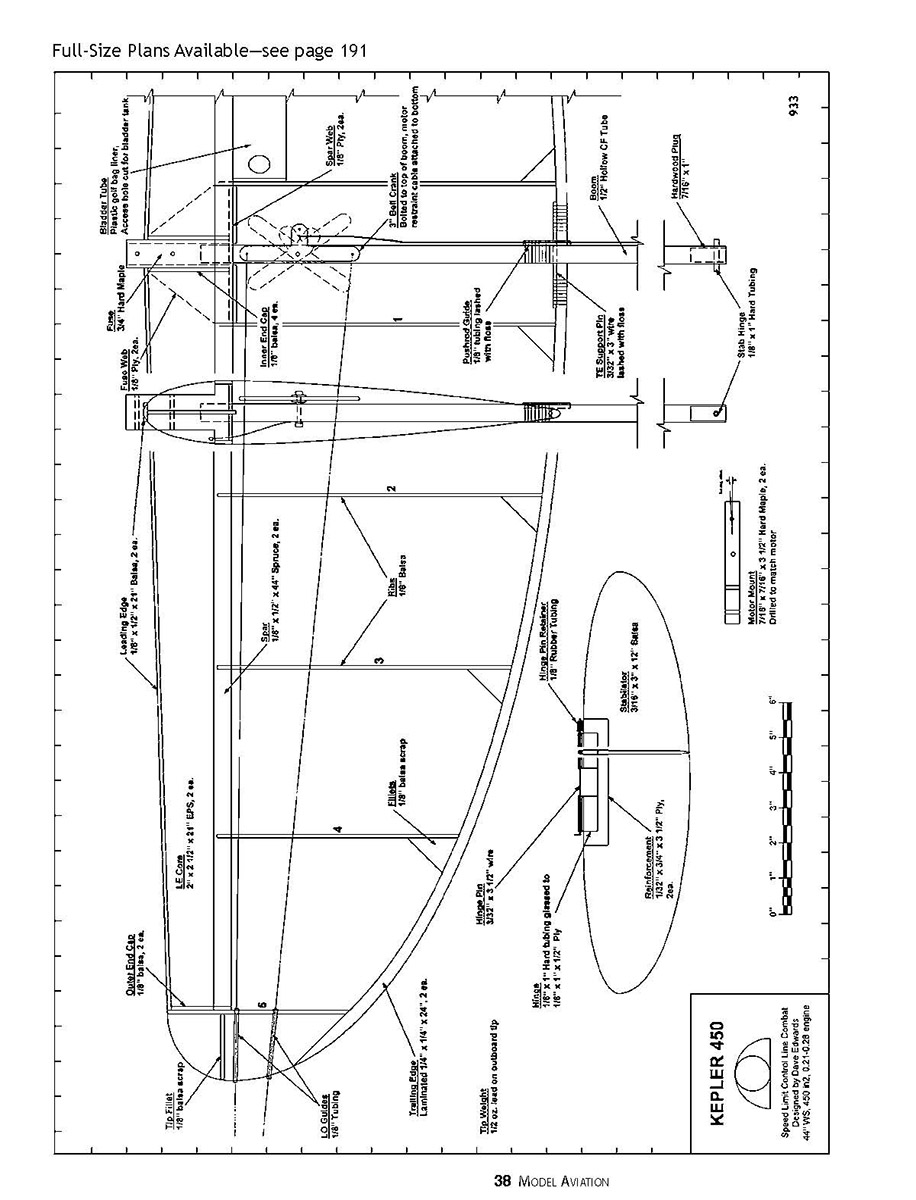
Kepler 450
Dave Edwards
IN THE PAST decade or so, there has been a significant rise in popularity of the Control Line speed-limit Combat events. This popularity can be attributed to the relatively low cost and complexity of equipment, the wide selection of engines and airplanes, and the balance of skill, competition, and fun experienced at the events. Success in the event requires a good mix of pilot skill and reliable equipment without overwhelming the competitor in either area.
The rules promote diverse approaches to aircraft design. It is common to see the top competitors fly F2D airplanes, tuned-down AMA Fast Combat models, hard-tank Slow Combat derivatives, and custom-built speed-limit airplanes. Construction varies from 20-year-old, built-up balsa designs to all-foam arrow-shaft wings and European F2D-style construction.
Engines range from low-powered .35s and .40s to tuned-down pre-Nelson Combat engines, .15 F2D engines, and a wide range of modern, inexpensive .21-.28 ABC engines. The latter provide adequate power, low cost ($50-$80 in most cases), low weight, and reliability when running pressurized fuel systems with 10% nitromethane.
Speed-limit Combat is an unofficial AMA event, and local rules have sprung up across the country. These rules are generally based on the AMA Combat events, with match procedures, pilot conduct, and scoring fairly consistent with the AMA rule book. One significant difference is that engine shutoff devices are not required if the speed limit is set at 75 mph or less.
Depending on the local rules, events are run using multiple elimination brackets or multiple rounds and point systems to determine pairings and placings. Some systems use the "kill" rule to end a match, and others give competitors a bonus for a match with no midair collisions or line entanglements.
Kepler 450
Fuselage is made from hard maple, slotted to accept fuselage webs. Spar, fuselage webs are Lite Ply glued to fuselage.
Foam-cutting templates, fixture with EPS foam after cutting. Templates are screwed to fixture; foam is lightly spray-cemented in place.
The elliptical wing is aesthetically pleasing and aerodynamically efficient. The long tailboom makes for a stable model.
Fixture used during spar/fuselage assembly. Spar fixtures are shown on left; foam/balsa LE, softwood spars are on right.
Complete fuselage/LE/spar/boom assembly. Boom is set into hole drilled into fuselage. Bladder tube fits between ribs one and three.
With the extended airframe life expectancy in the event, some effort has been put
CONSTRUCTION
Materials and Prep Work: The materials are straightforward. All balsa used in the wing should be 1/8 medium-hard—approximately two 3 x 36-inch sheets per airplane. Use harder balsa for the wingtips and LE. Spars and TEs are softwood. (Spruce and pine are acceptable; aspen from the local home center works well and is available in a variety of sizes.) The fuselage is made from solid, hard maple.
The boom is 1/2-inch CF tubing or arrow shaft, which is available from various mail-order houses. The foam LE is EPS; the white expanded-bead type or the pink extruded type is acceptable. The latter is more workable but adds a bit of weight. The bladder tube is made from a section of a plastic golf-bag liner.
Epoxy can be used for all glue joints requiring significant strength, such as the fuselage/web assembly. White or yellow wood glues are preferable for all foam-to-wood gluing. White glues take longer to dry, but they provide sufficient time to set up the joints correctly; this is particularly important when gluing the fuselage, spars, and foam LEs. Cyanoacrylate glue (CyA) can be used for all other wood-to-wood or wood-to-CF joints but should generally not be used on foam.
Some up-front work is needed to make building easier and faster, such as making three fixtures and a layout table. The fixtures are required for cutting the foam LE, assembling the LEs and fuselage, and bending the TEs. Fabrication of each will be discussed as it is used in construction. Plan on making two or three airplanes at once, because time and effort can be saved in larger production runs. An emphasis on light, strong construction will pay dividends on the field.
As with so many things in modeling, methods and approaches are borrowed and traded between builders and pilots. This airplane's construction borrows techniques from various sources, but particularly from the all-foam designs of Phil Cartier and the F2D designs of Loet Wakkerman. Loet's Web site outlines the foam-leading-edge construction methods used here.
Fuselage: The fuselage is constructed with a solid-maple center-section from the spars forward and a CF boom rearward to a stabilator hinge. The 1/8 plywood spar webs and fuselage webs add rigidity around the engine mount. The maple block in the center is made by ripping a 1 5/8-inch hard-maple plank from a 3/4-inch board using a table or band saw.
Using a table saw set up with a 1/8-inch kerf blade, a 1/8-inch-deep channel is cut down the center of each side for the fuselage webs. The fuselage is cut to length (27 1/2 inches), and the section forward of the spar is cut down to match the engine-mount spacing (1 1/4 inches for most .25 engines).
The engine mounts, typically aluminum or hard maple, are mounted to the fuselage using wood screws or long 4-40 machine screws. An engine turn-out of 2 to 4° is desirable, so lay out the engine-mount holes accordingly. The fuselage, fuselage webs, and spar webs can be glued together with epoxy, thick CyA, or wood glue. Strength here is a must, and tight-fitting joints are needed.
LE Assembly: Cutting accurate foam LEs is not difficult, but it takes practice and the right equipment. The process is easier than cutting full wings, given their small size and simple shape. A foam cutter is needed. A 0–120 VAC variable transformer is ideal for a power supply and can be found at a surplus electrical supply house. A 24-inch bow with a stainless cutting wire is also needed. A steel guitar string or similar substitute can be used.
(Editor's note: The best choice for the cutting wire is probably 1.5 ohms/foot)
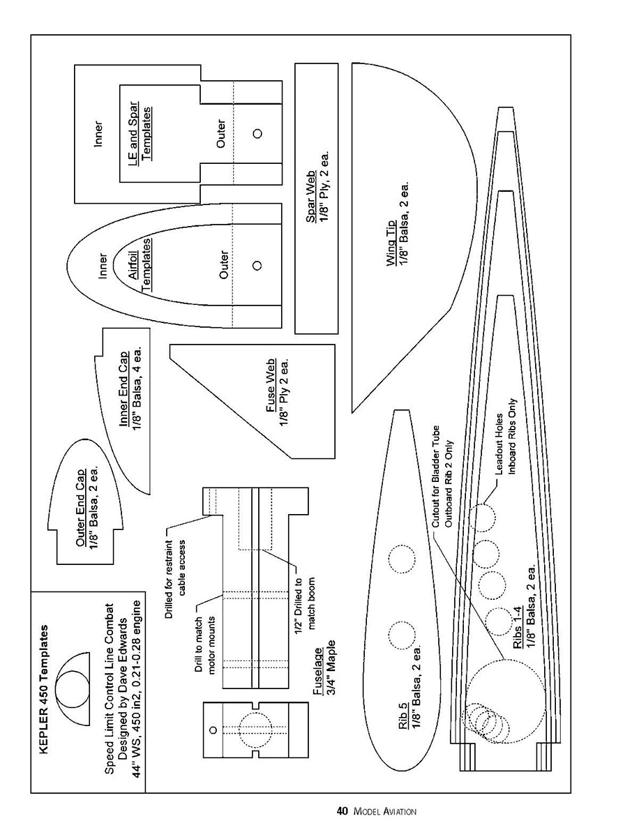
Kepler 450 Templates
Inner LE and Spar Templates Outer
Inner Airfoil Templates Outer
Spar Web 1/8" Ply, 2 ea.
Wing Tip 1/8" Balsa, 2 ea.
Inner End Cap 1/8" Balsa, 4 ea.
Outer End Cap 1/8" Balsa, 2 ea.
Fuse Web 1/8" Ply, 2 ea.
Rib 5 1/8" Balsa, 2 ea.
Ribs 1-4 1/8" Balsa, 2 ea.
Cutout for Bladder Tube Outboard Rib 2 Only
Leadout Holes Inboard Ribs Only
Fuselage 3/4" Maple
Drill to match motor mounts
Drilled for restraint cable access
1/2" Drilled to match boom
KEPLER 450 Templates
Speed Limit Control Line Combat Designed by Dave Edwards 44" WS, 450 in2, .21-.28 engine
be cut to accommodate the fuselage web, and some trimming is needed to permit the spar web to fit snugly beneath the spar. A small, flat file 5/16-inch thick cuts this nicely.
A pair of fixtures will be helpful for the next step; each fixture consists of a pair of 1-in. hardwood wooden strips which hold the spars firmly against the foam during assembly. Bolts placed every four inches in the fixture help keep the assembly tight during set-up.
Glue should be used for the assembly since it gives sufficient time for setting yet forms a strong bond to the fuselage, spars, and the foam. Apply glue liberally to the fuselage sections and just enough in the spar channels to form a good bond without squeezing out during assembly. Use the fixtures, and clamp the assembly together. Once dry, they should form a solid, straight LE/fuselage assembly that will become the heart of the airplane.
At this point the foam can be covered with wrapping paper and wallpaper paste for added stiffness, durability, and appearance. This adds some weight but toughens the foam surface considerably. This step is unnecessary when using the pink extruded foam (except perhaps to improve appearance).
The boom mounting hole in the rear of the fuselage is carefully drilled (a drill press with a vise is good for this step) perpendicularly through the spar webbing into the maple fuselage. The boom, cut a few inches long to allow for balancing, can then be drilled for the bellcrank and TE support pin and glued into the fuselage with CYA.
Wing: Adding ribs, tips, mid and the TE to the mold requires a solid, flat working surface. A layout table with blocks glued in place to hold the wingtips, TE, and fuselage centerlines one inch off the surface works well. The LE assembly can be laid on the table and the tips and Ribs 5 can be glued in place.
The TE shape can be marked and transferred to a piece of 3/16-inch scrap wood to make a bending fixture. The bending fixture is cut one inch thick along the desired shape of the TE and needs to be a couple inches longer on each end than the final TE.
Using a table saw or a band saw, rip three pieces of scrapwood into 3/32 x 1 x 24-inch sections. These should bend easily to the shape of the TE fixture. Laminate the three strips with wood glue, and clamp them to the fixture every few inches. Let dry for at least 24 hours, then remove from the fixture. Rip this curved piece to 1/8-inch thickness, and shape with a hand plane and sandpaper. The finished TEs should maintain the curved shape and still have some flexibility.
Dry-fit the fuselage assembly, TE, and the fuselage centerlines one inch off the surface works well. The LE assembly can be laid on the table and the tips and Ribs 5 can be glued in place. The TE shape can be marked and transferred to a piece of 3/16-inch scrap wood to make a bending fixture. The bending fixture is cut one inch thick along the desired shape of the TE and needs to be a couple inches longer on each end than the final TE. Using a table saw or a band saw, rip three pieces of scrap wood into 3/32 x 1 x 24-inch sections. These should bend easily to the shape of the TE fixture. Laminate the three strips with wood glue, and clamp them to the fixture every few inches. Let dry for at least 24 hours, then remove from the fixture. Rip this curved piece to 1/8-inch thickness, and shape with a hand plane and sandpaper. The finished TEs should maintain the curved shape and still have some flexibility. Dry-fit the fuselage assembly, TE, and wing. When satisfied, glue the wing in place using CYA. Once dry, the wing should be glassed over with lightweight fiberglass cloth and epoxy to add strength and provide a smooth finish.
Stabilator: The stabilator is made from a piece of 3/16 x 3 x 12-inch balsa shaped as desired. The hinge is made by fiberglassing a 1/8-inch-diameter brass tube to a 1/2-inch strip of 1/8 plywood. Doing a strip four to eight inches long then cutting one-inch sections makes this job easier and faster.
Using a piece of 3/32-inch wire as a hinge pin to align the tubing, the hinges can be glued into the stabilizer and reinforced top and bottom. This makes for a very tough stabilizer that can be changed quickly if damaged.
A piece of 1/8-inch-diameter hard tubing is glued as a hinge into the boom, which should be reinforced with a hardwood dowel. Any exposed wood on the stabilizer and fuselage should be fuelproofed with epoxy, dope, or polyurethane varnish.
With the engine installed, the airplane should balance at the spar. In general, the boom length and engine mounts can be adjusted to move the center of gravity forward and back if needed. For a fixed center-of-gravity location, longer booms tend to have better tracking and smoother turning; shorter booms result in quicker response to controls. Build it to suit your flying preference.
Flying: In the air at 70-80 mph, the Kepler 450 turns well and stays out even in moderate winds. Because of the lower aspect, speed-limit models are more sensitive to trim than most AMA Fast Combat airplanes. Adjustment of the engine turn, tip weight, and leadout position are more critical.
A well-trimmed airplane should have no problem staying out during the most violent maneuvers, even on the upwind side of the circle. This can be a significant advantage when flying opponents who are limited by equipment performance.
Most of the modern plain-bearing .21-.25 engines will have no problem with 70-80 mph speeds, usually requiring a low-pitch, eight-inch propeller and a restricted venturi to keep them below the limit. A hot engine such as the Norvel .25PB without a venturi restriction will pull the model at approximately 100 mph, making it a good practice airplane to step up to AMA Fast Combat events.
A setup with a reliable engine, low-nitro fuel, a latex bladder, a fine-threaded remote needle valve, and an adjustable venturi will make contests more enjoyable, with more emphasis on flying than on starting engines and keeping the equipment performing. MA
David P. Edwards 9 Ardsley Rd. Hillsborough NJ 08844
Sources:
Phil Cartier, The Core House (CF boom, covering, bladder materials)
USI Laminates (covering)
3M® (foam)
Loet Wakkerman (construction techniques) http://home.wxs.nl/~wakke007
Transcribed from original scans by AI. Minor OCR errors may remain.

