
Killer Incidence Meter
by Derek Moran
Whether you build from scratch, kits, ARFs, or go RTF, you need a tool to set, verify, and adjust the angle of your model’s flying surfaces. Your airplane will never perform to its potential if it’s not straight and aligned as the designer intended. I own and have used the commercially available incidence tools. The Killer Incidence Meter, or KIM, goes a step beyond.
Why should you go through the trouble of making this incidence meter when you could buy one?
- The KIM is simple and accurate. You can have confidence in its readings.
- The KIM is adaptable. You can configure it to measure in a way that makes sense to you.
- The KIM is expandable. You can make and install custom fixtures that enable you to measure features that would otherwise be difficult or impossible.
- The KIM will give you the fun and satisfaction of making a precision instrument from materials you have in your scrap box.
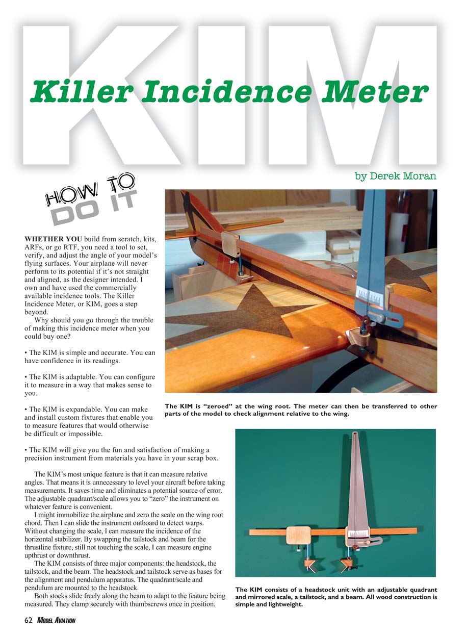
The KIM’s most unique feature is that it can measure relative angles. That means it is unnecessary to level your aircraft before taking measurements. It saves time and eliminates a potential source of error. The adjustable quadrant/scale allows you to “zero” the instrument on whatever feature is convenient.
I might immobilize the airplane and zero the scale on the wing root chord. Then I can slide the instrument outboard to detect warps. Without changing the scale, I can measure the incidence of the horizontal stabilizer. By swapping the tailstock and beam for the thrustline fixture, still not touching the scale, I can measure engine upthrust or downthrust.
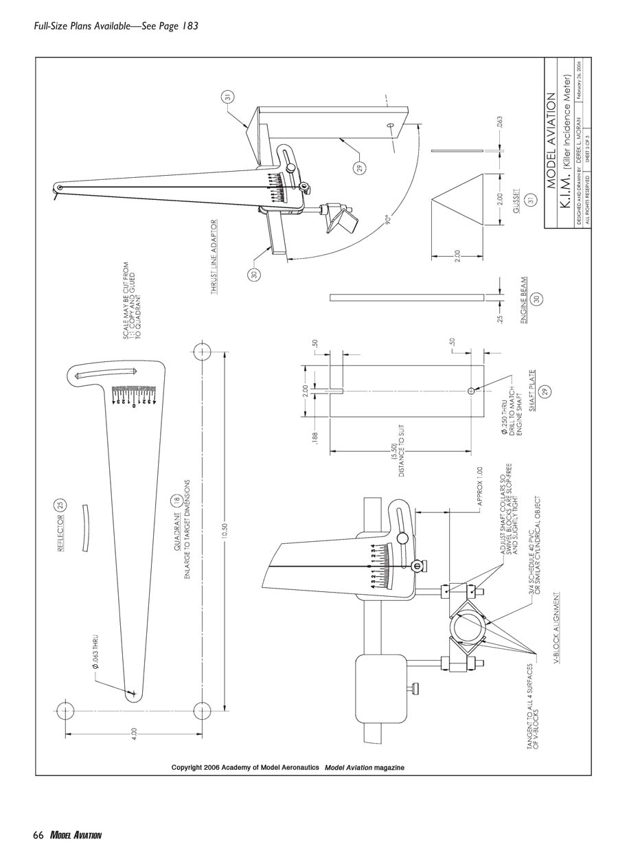
Overview and Major Components
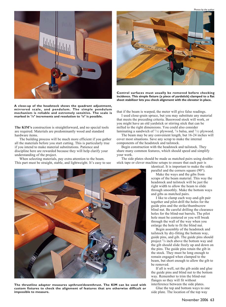
The KIM consists of three major components: the headstock, the tailstock, and the beam. The headstock and tailstock serve as bases for the alignment and pendulum apparatus. The quadrant/scale and pendulum are mounted to the headstock. Both stocks slide freely along the beam to adapt to the feature being measured. They clamp securely with thumbscrews once in position.
Materials and Beam Considerations
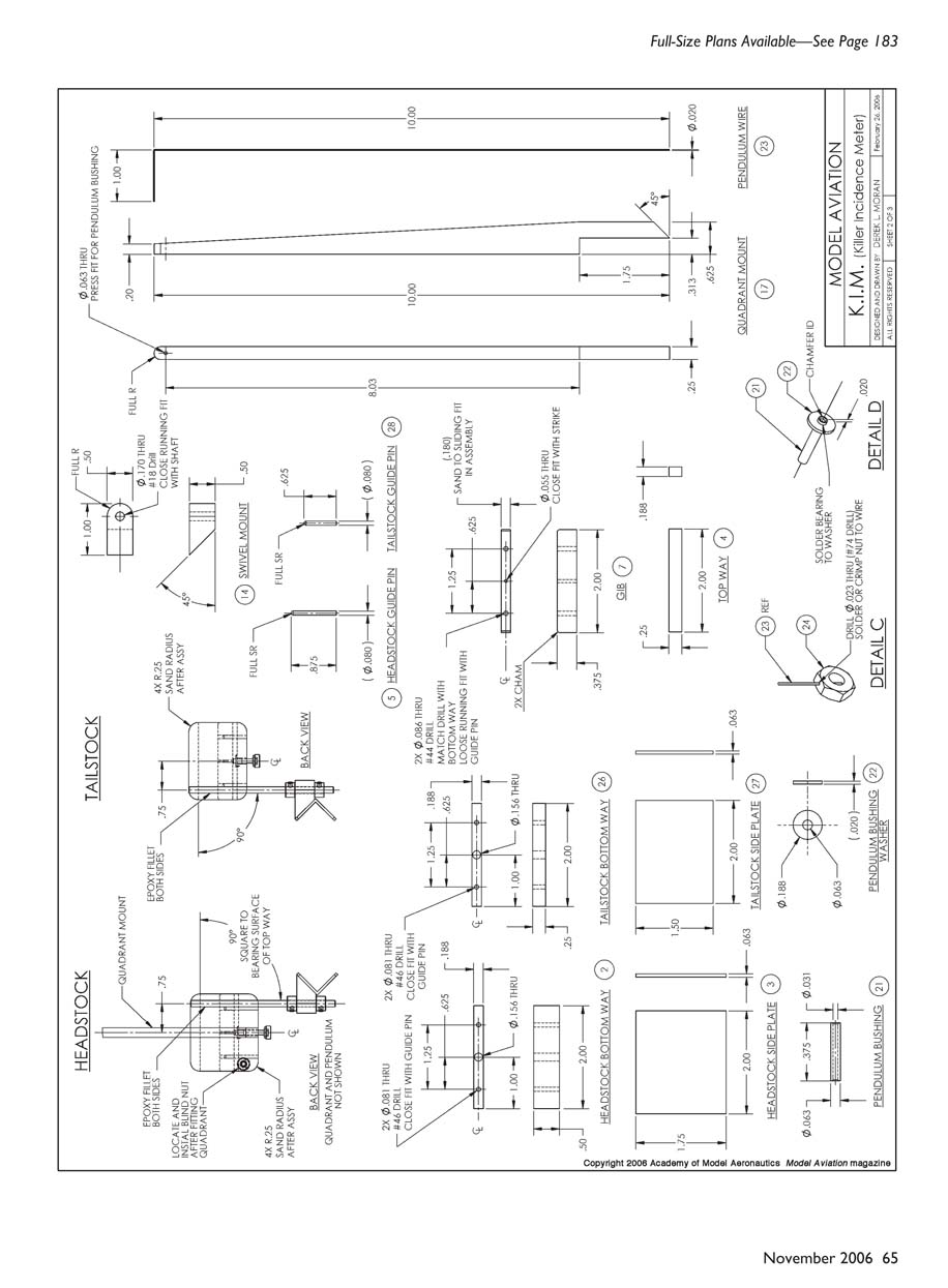
It is critical that the beam be straight and stable; if the beam is warped, the meter will give false readings. I used close-grain spruce, but you may substitute any material that meets those criteria. Basswood stock will work, or you might have an old yardstick or stirring stick that can be milled to the right dimensions. You could also consider laminating a sandwich of 1/32" plywood, 1/8" balsa, and 1/32" plywood. The beam length may be any convenient length, but 16–24 inches will cover most situations. Save any scrap to make the internal components of the headstock and tailstock.
Headstock and Tailstock Construction
Begin construction with the headstock and tailstock. They share many common features, which should speed and simplify your work.
- Make the side plates as matched pairs using double-stick tape or clever machine setups to ensure that each pair is identical.
- Make the sides parallel and the corners square (90°).
- Make the ways and the gibs from scraps of the beam material so the headstock and tailstock will be the right width to allow the beam to slide smoothly.
- Make the bottom ways and gibs as matched pairs. Clamp each way-and-gib pair together and pilot-drill the holes for the guide pins and the strike/thumbscrew blind nut.
Be careful drilling the clearance holes for the blind-nut barrels. The pilot hole must be centered or you will break through the wall of the way when you enlarge the hole to fit the blind nut.
Begin assembly of the headstock and tailstock by dry-fitting the bottom way, guide pins, and gib. The guide pins should project 3/8" above the bottom way and the gib should slide freely up and down on the pins. The guide pins retain the gib in the stock. They must be long enough to remain engaged when clamped to the beam, but short enough to allow the gib to be removed.
If all is well, set the gib aside and glue the guide pins and blind nut to the bottom way. Remember to trim the blind-nut flanges so they will fit without interference between the side plates.
Glue the top and bottom ways to one side plate. The location of the top way should leave a small clearance between the top way and the bottom way when the side plates are assembled to allow the gib to move freely. Use a small clamp to hold the top way in place while you pilot-drill and install the blind nut for the strike/thumbscrew. Next glue the other side plate in place and insert the guide pins, gib, and strike/thumbscrew. If the fit is tight, remove the gib and sand it to fit. When the assembly slides freely, it is time to install the scale/quadrant, pendulum and clamp.
Fix the orientation of the assembly to the beam so the top way is parallel to the long edge and perpendicular to the short edge of the side plate. Once that has set, glue on the other side plate.
Remove any glue squeeze-out on interior surfaces because it could prevent free movement of the beam and gib. Sand the edges square and smooth, and radius the corners as shown on the plans.
Each gib receives a small brad to serve as a strike. The thumbscrew bears on the head of the brad to prevent damage to the wood under clamping pressure. Trim the brad to length (1/4") and glue it to the side of the gib that faces the bottom way.
Now is a good time to sand the gib faces so they will be .005–.010" thinner than the top and bottom ways. This will ensure that the gib slides freely between the side plates. Also sand a slight chamfer or radius on the ends to prevent the gib from digging into the beam as the stock is moved.
Swivel Shafts, Quadrant Mount and V-blocks
- Abrade and degrease the bond area of the two swivel shafts.
- The swivel shafts are attached in two steps: first make a small fixture to hold the shafts perpendicular to the bearing face of the top way; second, tack-glue the swivel shafts to the back face of each stock and apply a neat fillet of J.B. Weld or similar epoxy with high-density filler.
- Glue the quadrant mount to the back of the headstock assembly. The quadrant mount should be square to the bearing surface of the top way.
- Assemble the swivel mount and the V-block using J.B. Weld. It is crucial for the beveled surface of the swivel mount to be precisely 45°.
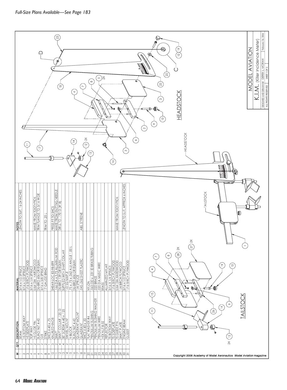
Quadrant, Scale, Mirror and Pendulum
Enlarge the plans sheet to the target dimensions to make full-size patterns for the quadrant, the scale, and the antiparallax mirror. The material you choose for the quadrant is noncritical, but it should be flat and easy to work. Packaged ABS and styrene sheet are available in most hobby shops and craft stores. Aluminized Mylar is a good choice for the mirror.
I cut the outline of my quadrant on the router, using a 1/2" plywood template and a flush trimmer bit. I also cut the radial clamping slot on the router. I made a fixture to pivot the quadrant on the .063" diameter hole and swing through the proper arc over a 1/8" straight cutter. If this sounds like too much work or you don't have the tools, cut the quadrant outline and slot with a hobby knife.
Spray a couple of light coats of clear lacquer or artist's fixative on the scale to preserve the print. Use 3M Super 77 Multipurpose Adhesive or a similar spray contact cement to attach the scale and the antiparallax mirror to the quadrant. Alternately, you could make a decal or print the scale image on adhesive-backed label stock.
There's nothing tricky about making the pendulum bushing. If you have a suitable washer in your odd-parts bin, you're in luck. I fabricated my washer from thin brass stock. When soldering, make sure the washer is perpendicular to the axis of the bushing. Also, try to prevent a solder fillet from forming on the rear face of the washer. If one does, file or scrape it away. Put a chamfer or radius on the inside edge of the bushing to prevent the pendulum wire from binding.
The pendulum is also easy to make. The only feature that needs attention is the small-diameter hole through the nut. I used a brass nut because it is slightly denser than steel and is easier to crimp or solder.
Temporarily mount the quadrant and mark the location of the clamp screw on the headstock. Drill and install the blind nut on the rear side plate.
Optional: Thrustline Adaptor
I have included plans for an optional fixture: the thrustline adaptor. It bolts to the engine crankshaft and enables you to measure positive and negative shaft-line angles. The thrustline adaptor is a simple assembly. The only thing worth noting is the importance of joining the beam and shaft plate at exactly 90°.
Finishing
No finish is required on the wooden parts, but if you feel compelled you can apply one or two coats of thinned clear dope.
Assembly and Final Adjustments
It's time for some assembly. You'll need three thumbscrews; two will be 1/2" long and one will be 3/4" long. Press the Shear-Loc knurled knobs onto the appropriate socket-head cap screws. If you don't have an arbor press, you can use your drill press. Tightly close the chuck jaws to prevent damage to the chuck.
- Install the gibs in the headstock and tailstock. The strike faces downward, toward the thumbscrew.
- Put in the thumbscrews (the longer one goes in the headstock) and slide the assembly onto the beam. The beam should glide smoothly through the stocks with little resistance and no side play. Adjust the fit by lightly sanding both sides of the beam.
- Test the action of the clamps. They should engage and lock with only light torque on the thumbscrew.
- Install and align the V-blocks. If you haven't already, drill the shaft collars to fit on the swivel shafts. Lock the headstock on the beam and install the shaft collars and swivel block on its shaft. The top of the swivel mount should be approximately 1" below the headstock. Adjust the collars so that the V-block/swivel mount is slop-free and slightly tight.
- Put the shaft collars and V-block/swivel mount on the tailstock, and slide it onto the beam.
You are going to need a lightweight, cylindrical object measuring roughly 1" in diameter and 3" long; clean, undamaged PVC pipe will work fine. Clamp this cylinder between the V-blocks.
- Adjust the tailstock swivel mount so the cylinder is tangent to both surfaces of each V-block. This usually takes a little fiddling and sometimes requires more than two hands.
- Once this adjustment is perfect, the centerline of each V-block is exactly the same distance from the bearing surface of the beam. Thus you can place the headstock and tailstock anywhere on the beam and be assured that no error will be added to the meter display.
Install the quadrant by pressing the pendulum bushing into the pivot hole in the quadrant mount. I did not glue the pendulum bushing to the quadrant mount. This makes it easy to remove or replace the quadrant if necessary. Likewise, the pendulum is not permanently attached. The 1" leg of the pendulum wire is enough to retain it during use.
Using the KIM
The KIM is easy and intuitive to use, and, as with any precision instrument, you must be logical and methodical to get valid, repeatable results. Before taking any measurements, you must immobilize the model.
At the very least you will need:
- a block under the fuselage ahead of the balance point,
- a block at the tail, and
- a block under each wing panel at midspan.
Weight or tape the airplane to these blocks to prevent any movement. Do not set the model on its landing gear and expect to get consistent readings. Consider making a fixture that is keyed to the model and to your workbench. This will allow you to check the airplane periodically with minimum setup time.
The first thing to do when using the KIM is to zero the scale. I like to start with the wing and place the meter as close as possible to the root.
- Clamp the headstock on the beam in a position that will result in roughly equal overhang past both stocks.
- Hold the headstock V-block on the leading edge (LE) while you slide the tailstock V-block to meet the trailing edge (TE). Align the meter parallel to the chord line. The V-blocks will self-center on the LE and TE and rotate to follow any taper in the wing panel.
- Apply light pressure to the tailstock V-block and clamp the tailstock. Loosen the quadrant-clamp thumbscrew.
- Move the pendulum assembly until the scale indicates zero. Tighten the quadrant clamp. Recheck the zero and, if necessary, nudge the pendulum until you are satisfied. I use a small piece of masking tape on the rear face of the headstock to protect the scale from wear during zeroing and operation.
You can now move the meter to other parts of the airplane and record relative incidence. For example, to check for washout, slide the meter outboard and set the V-blocks on the LE and TE at the outboard location. The scale will show any difference in incidence without needing to change the zero.
To measure stabilizer incidence, swap the tailstock for the stabilizer fixture or attach the stabilizer directly in the V-blocks if appropriate. Zero on the wing root and then move the meter to the stabilizer to read the incidence directly.
To check thrustline, bolt the thrustline adaptor to the engine crankshaft and install the assembly between the V-blocks. Zero the meter to the wing root, then install the engine and read the thrust angle from the scale. The thrustline adaptor makes it easy to measure positive or negative upthrust.
When the pendulum comes to rest, adjust the quadrant so that the zero line on the scale is collinear with the pendulum, and tighten the clamp thumbscrew. The antiparallax mirror will enable you to take accurate readings.
The mirror reflects an image of the backside of the pendulum wire. When you are looking directly at the wire, perpendicular to the scale, that image is obscured by the wire itself, and the reading you take from the scale is correct. If you are looking at a slight angle, you will see the reflected image of the wire beside the wire itself. A reading taken from this position will be incorrect.
Now is a good time to warn you that it often takes quite a while for the pendulum to settle. It is quite sensitive and easily affected by drafts and vibrations. In lieu of a suitably simple and effective damping device, I have decided to accept its extreme sensitivity as a good thing. If you are gluing a wing or stabilizer, it gives you plenty of time to ponder the permanence of the act you are about to commit.
With the quadrant zeroed, the meter can be transferred anywhere on the model and give valid readings, as long as the aircraft is not moved. The entire headstock can even be removed from the beam and installed on custom fixtures.
Credits
Credit Dan Rutherford for naming this instrument. He has a knack for coining clever, humorous, descriptive monikers. I was quite flattered and the name has stuck. Dan has made several KIMs that he intends to give as gifts to certain friends—but only after they finish building their aircraft!
MA
Derek Moran [email protected]
Transcribed from original scans by AI. Minor OCR errors may remain.

