
KINGCOBRA
RELIVE THE EXCITEMENT OF POSTWAR RACING
by Mark Rittinger
Bell Aircraft Corporation's unique mid-engine P-63 Kingcobra was a descendant of the Bell P-39 Airacobra. The Airacobra lacked a supercharger, limiting it to low-altitude work. Although effective for strafing and ground targets, the P-39 suffered in engaging a flying enemy. Bell went back to the drawing board and modified two P-39Es into P-63s.
Although the P-39 and P-63 looked similar, the Kingcobra was significantly larger, with an extra 4.3 feet of wingspan and an extra 2.5 feet in length. It also had a new laminar-flow airfoil, metal-covered ailerons and elevator, full flaps, a four-blade propeller, and a two-stage supercharger.
With a top speed of 426 mph, it was one of the fastest aircraft of its time. Add in the cannon's firepower, and it was also deadly. The Kingcobra and the Airacobra were also the only Allied fighters of World War II with a cockpit forward of the wing.
Following the war, there was a surplus of wartime aircraft. A leftover fighter could be bought for $1,500 and some still had full fuel tanks! With the return of air racing in Cleveland, many chose to "hot rod" WWII fighters such as the P-51, P-39, P-38, Corsair, and the Kingcobra. Several carried garish but easily seen color schemes. I like the odd types, so I decided to do an electric-powered Kingcobra in several versions.
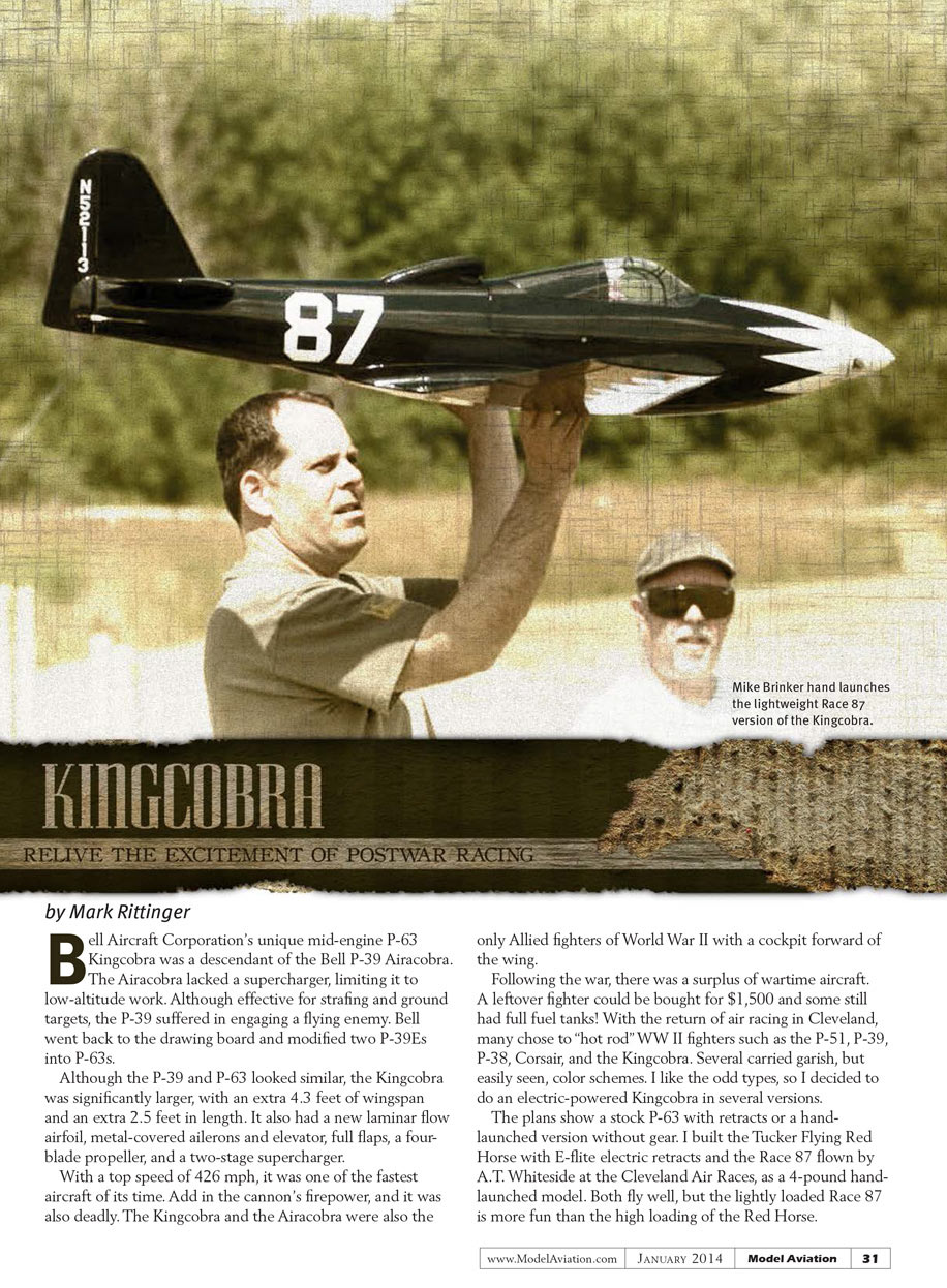
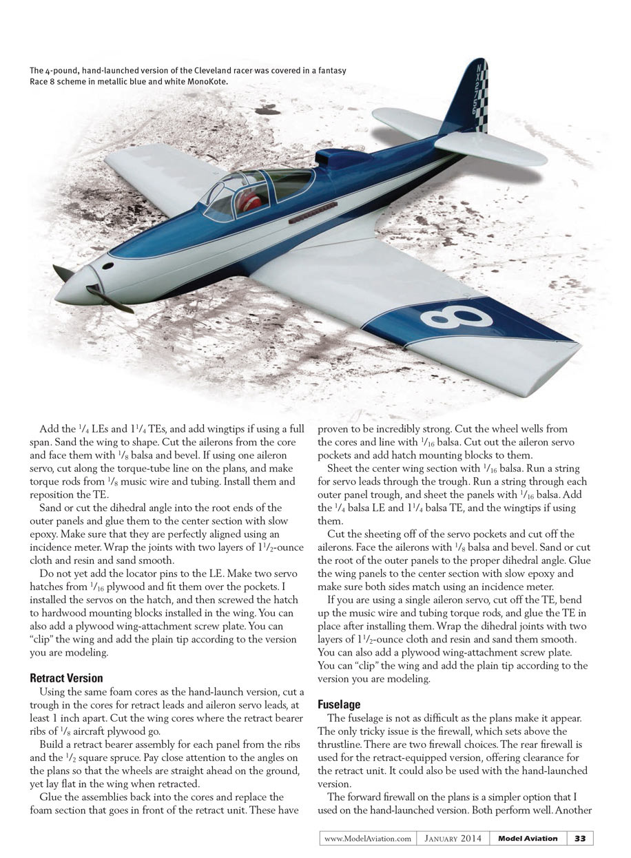
The plans show a stock P-63 with retracts or a hand-launched version without gear. I built the Tucker Flying Red Horse with E-flite electric retracts and the Race 87 flown by A.T. Whiteside at the Cleveland Air Races as a 4-pound hand-launched model. Both fly well, but the lightly loaded Race 87 is much more fun than the high loading of the Red Horse.
There are many versions of the racer, including a "pinball target" (manned flying target for gunnery practice) or a World War II fighter. If you want a smooth-flying warbird that builds quickly, order a set of plans and follow along as I build a seldom-modeled fighter.
Equipment
- E-flite Power 32 motor
- 60-amp ESC
- Three-cell (3S) 5,000 mAh 30C LiPo battery
- Radio with a minimum of four channels (five if using retracts)
- 3-inch Great Planes electric spinner
- APC propeller: 14 x 10 or 15 x 8
- Optional: E-flite .25-.46 electric retracts with 90° nose and 85° mains
- 2-1/4-inch nose wheel and 3-1/2-inch main wheels
No fancy computer radios are needed. It flies well without any mixing or exponential.
Building
Although the Kingcobra is not hard to build, it is not a beginner's model. This is an overview rather than step-by-step instructions. Decide which variant you want to build and whether you are using an undercarriage. Undercarriages add weight and complexity but are neat to fly with.
Hand launching the 4-pound model is easy with about 125 watts per pound, and it flies right out of your hand. I can easily hand-launch mine despite its considerable size; the deep, large handholds under the CG help. The choice is yours.
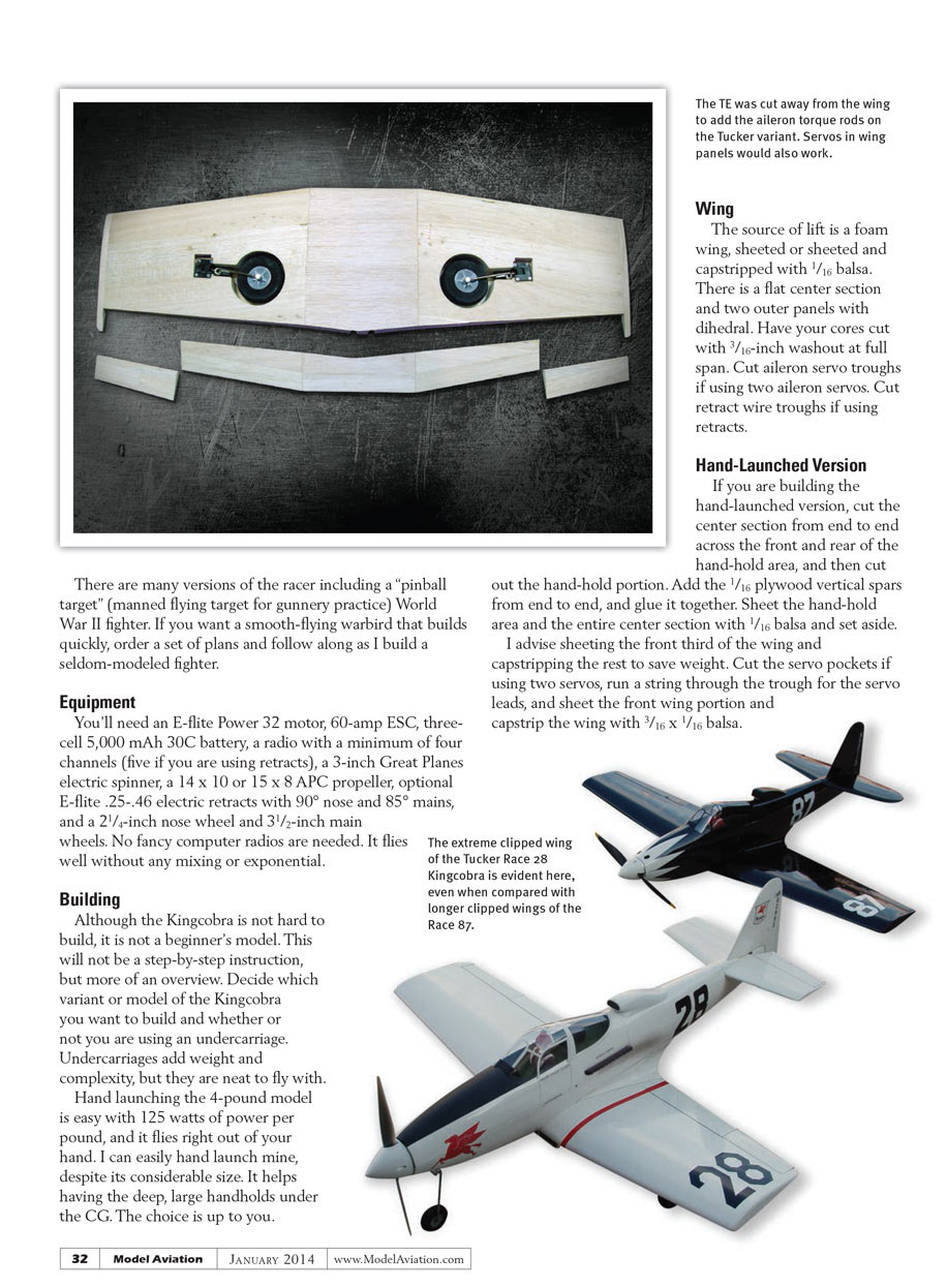
Wing
The wing is a foam core, sheeted or sheeted-and-capstripped with 1/16-inch balsa. There is a flat center section and two outer panels with dihedral. Have your cores cut with 3/16-inch washout at full span. Cut aileron servo troughs if using two aileron servos. Cut retract wire troughs if using retracts.
Hand-Launched Version
- Cut the center section from end to end across the front and rear of the hand-hold area, then cut out the hand-hold portion.
- Add 1/16 plywood vertical spars from end to end and glue together.
- Sheet the hand-hold area and the entire center section with 1/16 balsa and set aside.
- Sheet the front third of the wing and capstrip the rest to save weight.
- Cut servo pockets if using two servos, run a string through the trough for servo leads, and sheet the front wing portion. Capstrip the remainder with 3/16 x 1/16 balsa.
- Add 1/4-inch leading edges (LEs) and 1-1/4-inch trailing edges (TEs); add wingtips if using a full span and sand to shape.
- Cut the ailerons from the core, face with 1/8 balsa, and bevel. If using one aileron servo, cut along the torque-tube line on the plans and make torque rods from 1/8 music wire and tubing; install and reposition the TE.
- Sand or cut the dihedral angle into the roots of the outer panels and glue them to the center section with slow epoxy. Ensure perfect alignment with an incidence meter.
- Wrap the joints with two layers of 1-1/2-ounce cloth and resin and sand smooth.
- Do not yet add the locator pins to the LE. Make two servo hatches from 1/16 plywood and fit them over the pockets. I installed the servos on the hatch and then screwed the hatch to hardwood mounting blocks installed in the wing. You can also add a plywood wing-attachment screw plate.
- You can "clip" the wing and add the plain tip according to the version you are modeling.
Retract Version
- Use the same foam cores as the hand-launch version; cut troughs for retract leads and aileron servo leads at least 1 inch apart.
- Cut the wing cores where the retract bearer ribs of 1/8 aircraft plywood go.
- Build a retract bearer assembly for each panel from the ribs and 1/2-square spruce, paying close attention to the angles on the plans so the wheels are straight ahead on the ground yet lie flat in the wing when retracted.
- Glue the assemblies back into the cores and replace the foam section that goes in front of the retract unit. These are incredibly strong.
- Cut the wheel wells from the cores and line with 1/16 balsa. Cut out the aileron servo pockets and add hatch mounting blocks.
- Sheet the center wing section with 1/16 balsa and run a string for servo leads through the trough. Run a string through each outer panel trough and sheet the panels with 1/16 balsa.
- Add the 1/4 balsa LE, 1-1/4 balsa TE, and wingtips if using them.
- Cut the sheeting off the servo pockets and cut off the ailerons. Face the ailerons with 1/8 balsa and bevel.
- Sand or cut the root of the outer panels to the proper dihedral angle. Glue the wing panels to the center section with slow epoxy and ensure both sides match using an incidence meter.
- If using a single aileron servo, cut off the TE, bend up the music wire and tubing torque rods, and glue the TE in place after installing them.
- Wrap the dihedral joints with two layers of 1-1/2-ounce cloth and resin and sand smooth.
- You can add a plywood wing-attachment screw plate and clip the wing or add a plain tip according to your chosen version.
Fuselage
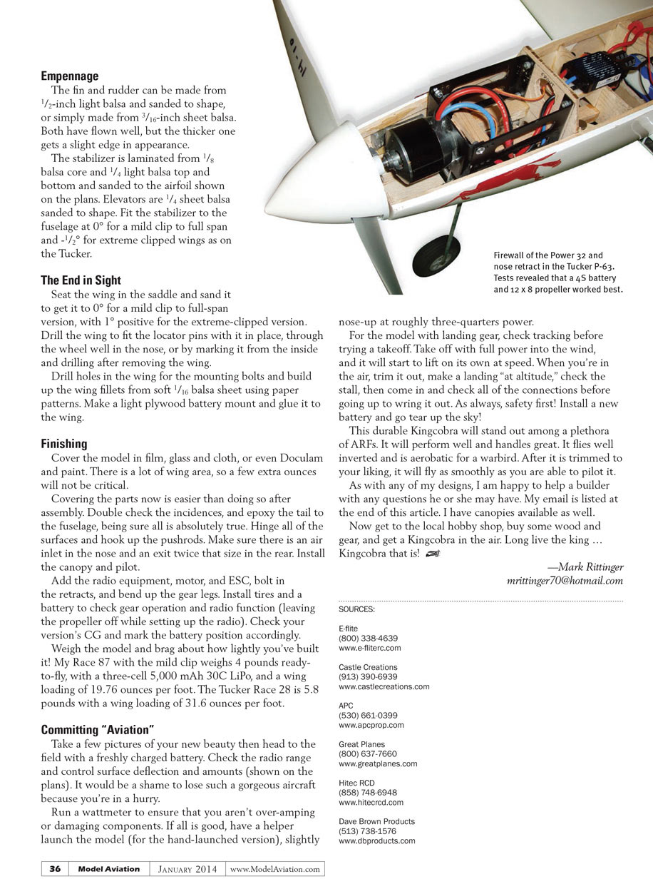
The fuselage is not as difficult as the plans may make it appear. The firewall is the only tricky issue because it sets above the thrustline. There are two firewall choices:
- The rear firewall is used for the retract-equipped version to offer clearance for the retract unit; it can also be used with the hand-launched version.
- The forward firewall on the plans is simpler and was used on my hand-launched version. Both perform well.
Another option would be a 1/4-inch plywood front firewall and reversing the motor shaft to mount it, although I have not tested that setup.
Construction steps and tips:
- Laminate the former material from two cross-grained layers of 1/16 balsa. Cut out all the formers and build up the bottom of the fuselage upside down on your building board.
- Using evenly matched 1/4 balsa thrustline stringers, build a frame on which to attach the formers. Add the crossbraces and glue all the lower fuselage formers except the 3/16-plywood firewall to the longerons. Use a temporary balsa firewall until the fuselage is off the board.
- After the formers are in place, add 1/8 balsa gussets to all but the firewall. Add the remaining stringers and laminate the front ones. Laminating the stringers from four pieces of 1/16 x 1/4 balsa helps them hold shape better.
- Add the plywood wing hold-down mounts and tap them for wing nylon bolts. Add the doublers to F4.
- Make a paper template for the fuselage sheeting and cut soft 3/32 balsa sides to size. Because you are bending wood, hard or medium balsa won't bend well.
- The fuselage lower section is sheeted from the thrustline stringer to the wing saddle and then cut to fit behind F8 to the keel on the rear section. Forward of the wing, the sheeting goes from the thrustline to the side stringer, and the lower nose portion is planked with 1/4 x 1/8 balsa and sanded smooth. The doubler on F4 is for gluing planks to.
- By using 48-inch-long wood, the sides can be sheeted using one piece per side. Wet the outside of the fuselage sheeting with hot tap water; it will start to bend on its own.
- Glue the sheeting to the thrustline stringer using medium to slow CA and use aliphatic glue on the rest of the stringers and formers. Carefully bend the sheeting to the wing saddle area and hold it in place with CA. Bend the rest to the keel and glue.
- Move to the front and glue the side stringer and the formers (except the temporary firewall). Repeat for the opposite side and then plank the lower front section.
- Add 3/32 hard balsa wing saddle doublers. Let it dry overnight and remove it from the board. It should be stiff.
- Remove the balsa firewall and carefully fit the 3/16-plywood firewall and gussets. Note the right thrust and remember the plan shows the bottom view.
- Add the 1/2-square retract bearers if using them, and cut the area open for the gear and wheel if needed.
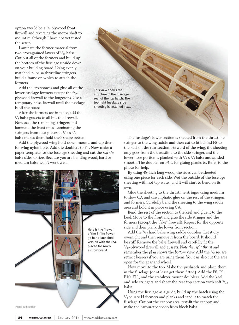
- Make the pushrods and place or fit them in the fuselage. Add F8–F11, the stabilizer mount doublers, the keel, side stringers, and sheet the rear top section with soft 3/32 balsa.
- Using the fuselage as a guide, build up the hatch using 1/4-square H formers and planks; sand to match the fuselage. Cut out the canopy area, test-fit the canopy, and make the carburetor scoop from block balsa.
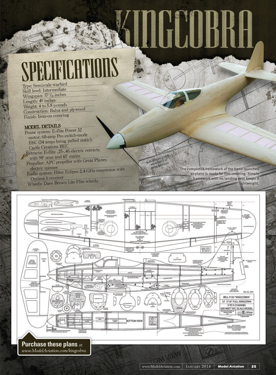
SPECIFICATIONS
- Type: Semiscale warbird
- Skill level: Intermediate
- Wingspan: 57-7/16 inches
- Length: 49 inches
- Weight: 4 to 5.8 pounds
- Construction: Balsa and plywood
- Finish: Iron-on covering
MODEL DETAILS
- Power system: E-flite Power 32 motor; 60-amp Pro switch-mode ESC (54 amps being pulled static); Castle Creations BEC
- Retracts: E-flite .25-.46 electric retracts with 90° nose and 85° mains
- Propeller: APC propeller with Great Planes electric spinner
- Radio system: Hitec Eclipse 2.4 GHz conversion with Optima 6 receiver
- Wheels: Dave Brown Lite Flite wheels
Empennage
The fin and rudder can be made from 1/2-inch light balsa and sanded to shape, or simply made from 3/16-inch sheet balsa. Both have flown well, but the thicker option gets a slight edge in appearance.
The stabilizer is laminated from a 1/8-inch balsa core and 1/4-inch light balsa top and bottom, and sanded to the airfoil shown on the plans. Elevators are 1/4-inch sheet balsa sanded to shape. Fit the stabilizer to the fuselage at 0° for a mild clip-to-full-span version and -1/2° for extreme clipped wings as on the Tucker.
The End in Sight
Seat the wing in the saddle and sand it to get it to 0° for a mild clip-to-full-span version, or 1° positive for the extreme-clipped version. Drill the wing to fit the locator pins with it in place, through the wheel well in the nose, or by marking it from the inside and drilling after removing the wing.
Drill holes in the wing for the mounting bolts and build up the wing fillets from soft 1/16 balsa sheet using paper patterns. Make a light plywood battery mount and glue it to the wing.
Finishing
Cover the model in film, glass and cloth, or even Doculam and paint. There is a lot of wing area, so a few extra ounces will not be critical.
Covering the parts now is easier than doing so after assembly. Double-check the incidences, and epoxy the tail to the fuselage, being sure everything is absolutely true. Hinge all surfaces and hook up the pushrods. Make sure there is an air inlet in the nose and an exit twice that size in the rear. Install the canopy and pilot.
Add the radio equipment, motor, and ESC; bolt in the retracts and bend up the gear legs. Install tires and a battery to check gear operation and radio function (leave the propeller off while setting up the radio). Check your version's CG and mark the battery position accordingly.
Weigh the model and brag about how lightly you've built it! My Race 87 with the mild clip weighs 4 pounds ready-to-fly with a three-cell 5,000 mAh 30C LiPo and has a wing loading of 19.76 ounces per square foot. The Tucker Race 28 is 5.8 pounds with a wing loading of 31.6 ounces per square foot.
Committing "Aviation"
Take a few pictures of your new beauty, then head to the field with a freshly charged battery. Check radio range and control-surface deflections and amounts (shown on the plans). It would be a shame to lose such a gorgeous aircraft because you're in a hurry.
Run a wattmeter to ensure you aren't over-amping or damaging components. If all is good, have a helper launch the hand-launched model slightly nose-up at roughly three-quarters power.
For the model with landing gear, check tracking before attempting a takeoff. Take off with full power into the wind; it will start to lift on its own at speed. When airborne, trim it out, make a landing "at altitude," check the stall, then come in and recheck all connections before going up to wring it out. As always, safety first! Install a new battery and go tear up the sky!
This durable Kingcobra will stand out among a plethora of ARFs. It performs well and handles great. It flies well inverted and is aerobatic for a warbird. After it is trimmed to your liking, it will fly as smoothly as you can pilot it.
As with any of my designs, I am happy to help a builder with any questions. My email is listed at the end of this article. I have canopies available as well.
Now get to the local hobby shop, buy some wood and gear, and get a Kingcobra in the air. Long live the king ... Kingcobra that is!
—Mark Rittinger [email protected]
SOURCES
- E-flite: (800) 338-4639 — www.e-fliterc.com
- Castle Creations: (913) 390-6939 — www.castlecreations.com
- APC: (530) 661-0399 — www.apcprop.com
- Great Planes: (800) 637-7660 — www.greatplanes.com
- Hitec RCD: (858) 748-6949 — www.hitecrcd.com
- Dave Brown Products: (513) 738-1576 — www.dbproducts.com
Transcribed from original scans by AI. Minor OCR errors may remain.

