
LAIRD SUPER SOLUTION
by Frank W. Beatty
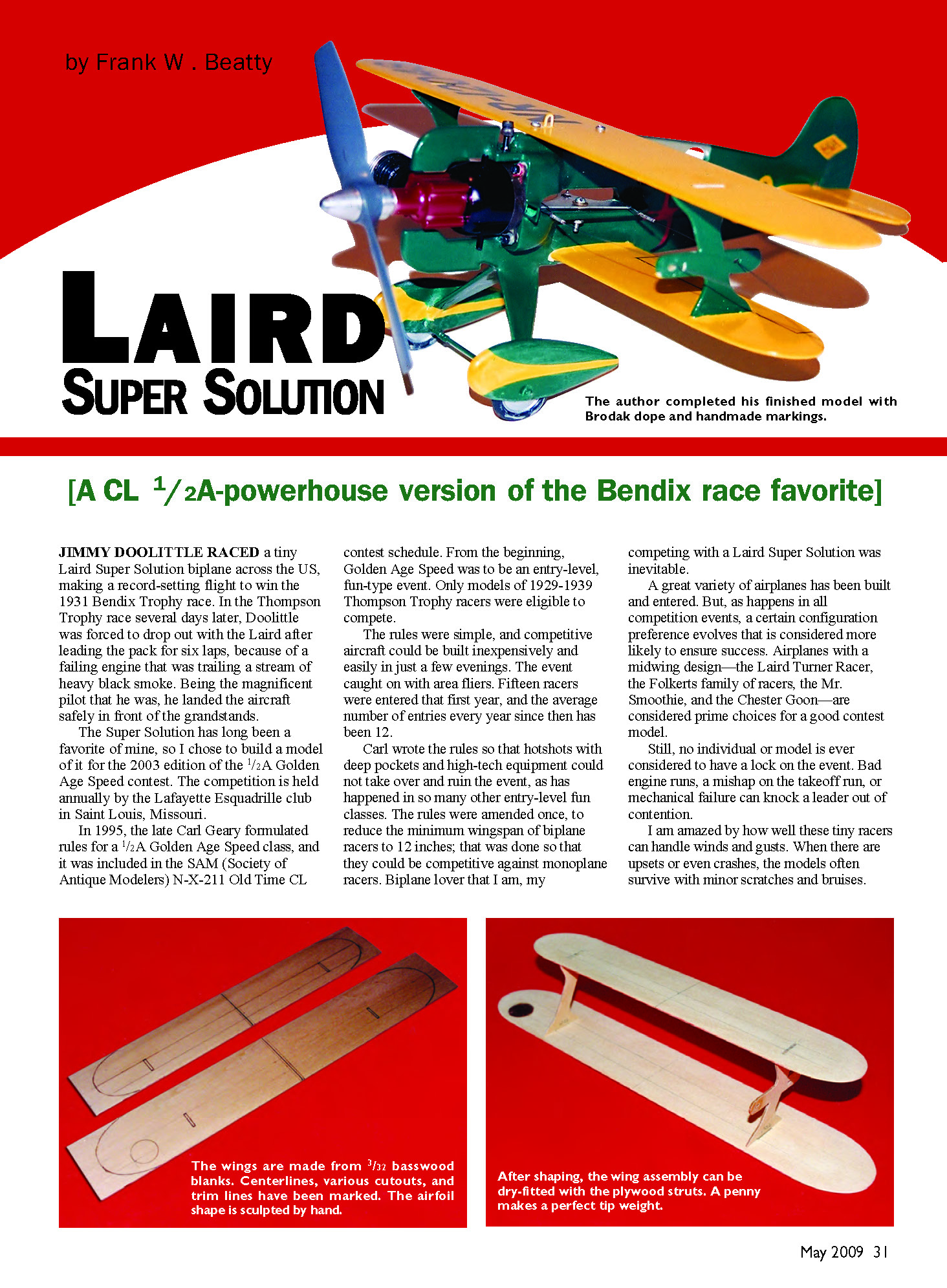
(A CL 1/2A‑powerhouse version of the Bendix race favorite)
Jimmy Doolittle raced a tiny Laird Super Solution biplane across the US, making a record‑setting flight to win the 1931 Bendix Trophy race. In the Thompson Trophy race several days later, Doolittle was forced to drop out with the Laird after leading the pack for six laps because of a failing engine that trailed a stream of heavy black smoke. Being the magnificent pilot that he was, he landed the aircraft safely in front of the grandstands.
The Super Solution has long been a favorite of mine, so I chose to build a model of it for the 2003 edition of the 1/2A Golden Age Speed contest. The competition is held annually by the Lafayette Esquadrille club in Saint Louis, Missouri.
In 1995, the late Carl Geary formulated rules for a 1/2A Golden Age Speed class, and it was included in the SAM (Society of Antique Modelers) N‑X‑211 Old Time CL contest schedule. From the beginning, Golden Age Speed was to be an entry‑level, fun‑type event. Only models of 1929–1939 Thompson Trophy racers were eligible to compete.
The rules were simple, and competitive aircraft could be built inexpensively and easily in just a few evenings. The event caught on with area fliers. Fifteen racers were entered that first year, and the average number of entries every year since then has been about 12.
Carl wrote the rules so that hotshots with deep pockets and high‑tech equipment could not take over and ruin the event, as has happened in so many other entry‑level fun classes. The rules were amended once to reduce the minimum wingspan of biplane racers to 12 inches so that they could be competitive against monoplane racers. Biplane lover that I am, my competing with a Laird Super Solution was inevitable.
A great variety of airplanes has been built and entered. But, as happens in all competition events, a certain configuration preference evolves that is considered more likely to ensure success. Airplanes with a midwing design—the Laird Turner Racer, the Folkerts family of racers, the Mr. Smoothie, and the Chester Goon—are considered prime choices for a good contest model.
Still, no individual or model is ever considered to have a lock on the event. Bad engine runs, a mishap on the takeoff run, or mechanical failure can knock a leader out of contention.
I am amazed by how well these tiny racers can handle winds and gusts. When there are upsets or even crashes, the models often survive with minor scratches and bruises.
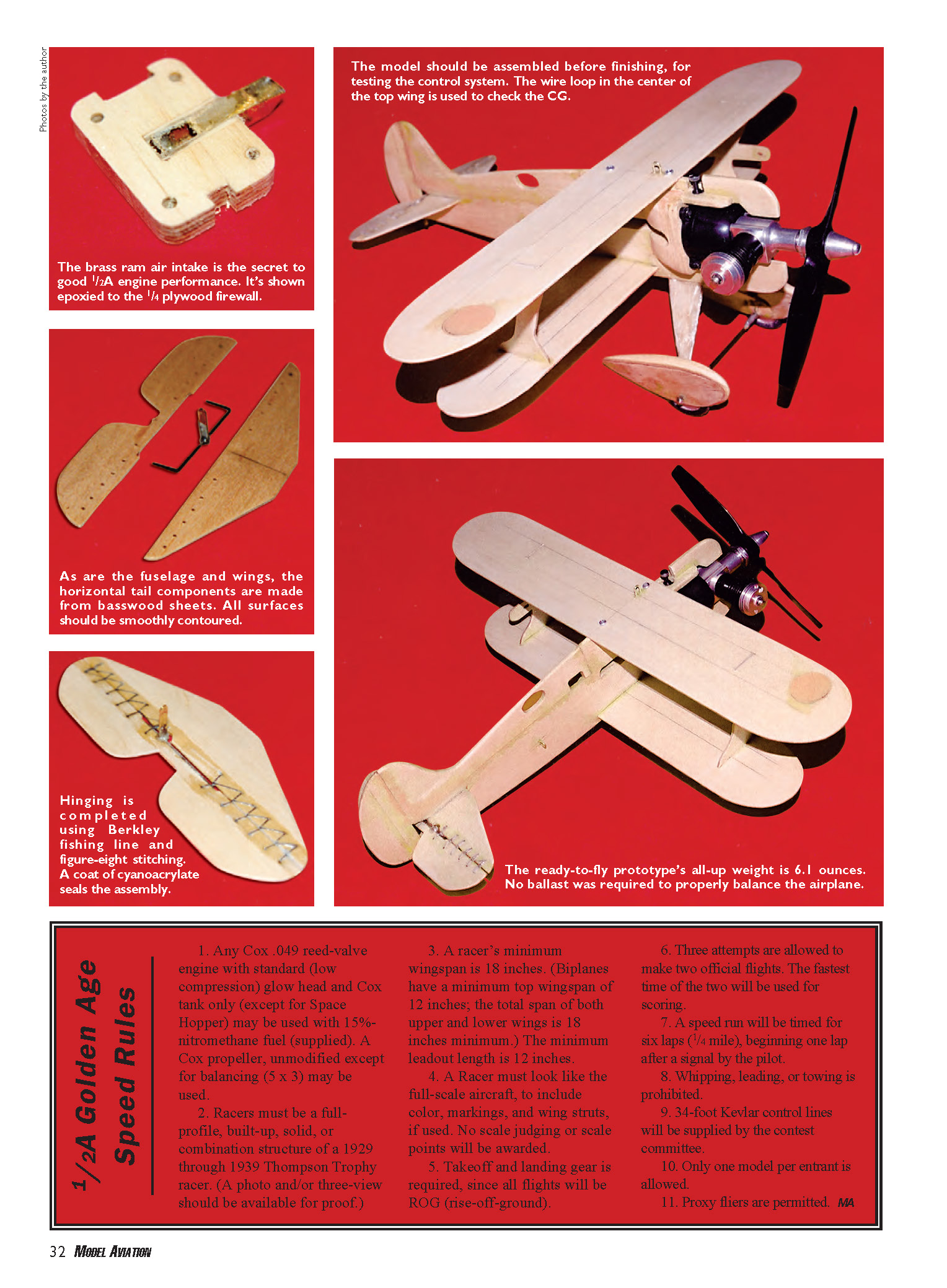
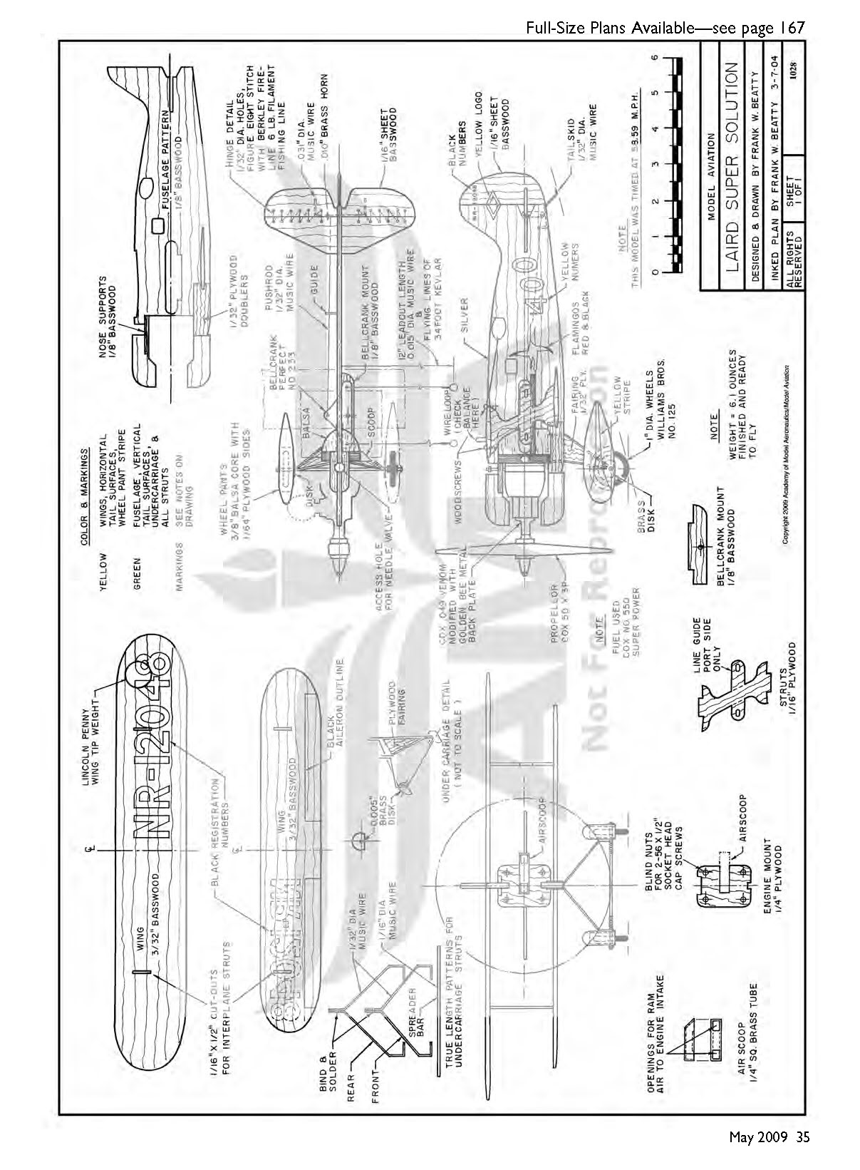
The brass ram air intake is the secret to good 1/2A engine performance. It’s epoxied to the 1/4‑inch plywood firewall.
As are the fuselage and wings, the horizontal tail components are made from basswood sheets. All surfaces should be smoothly contoured.
The model should be assembled before finishing, for testing the control system. The wire loop in the center of the top wing is used to check the CG.
The ready‑to‑fly prototype’s all‑up weight is 6.1 ounces. No ballast was required to properly balance the airplane.
1/2A Golden Age Speed Rules
- Any Cox .049 reed‑valve engine with standard (low compression) glow head and Cox tank only (except for Space Hopper) may be used with 15% nitromethane fuel (supplied). A Cox propeller, unmodified except for balancing (5 x 3), may be used.
- Racers must be a full‑profile, built‑up, solid, or combination structure of a 1929 through 1939 Thompson Trophy racer. (A photo and/or three‑view should be available for proof.)
- A racer’s minimum wingspan is 18 inches. (Biplanes have a minimum top wingspan of 12 inches; the total span of both upper and lower wings is 18 inches minimum.) The minimum leadout length is 12 inches.
- A racer must look like the full‑scale aircraft, to include color, markings, and wing struts, if used. No scale judging or scale points will be awarded.
- Takeoff and landing gear is required, since all flights will be ROG (rise‑off‑ground).
- Three attempts are allowed to make two official flights. The fastest time of the two will be used for scoring.
- A speed run will be timed for six laps (1/4 mile), beginning one lap after a signal by the pilot.
- Whipping, leading, or towing is prohibited.
- 34‑foot Kevlar control lines will be supplied by the contest committee.
- Only one model per entrant is allowed.
- Proxy fliers are permitted.
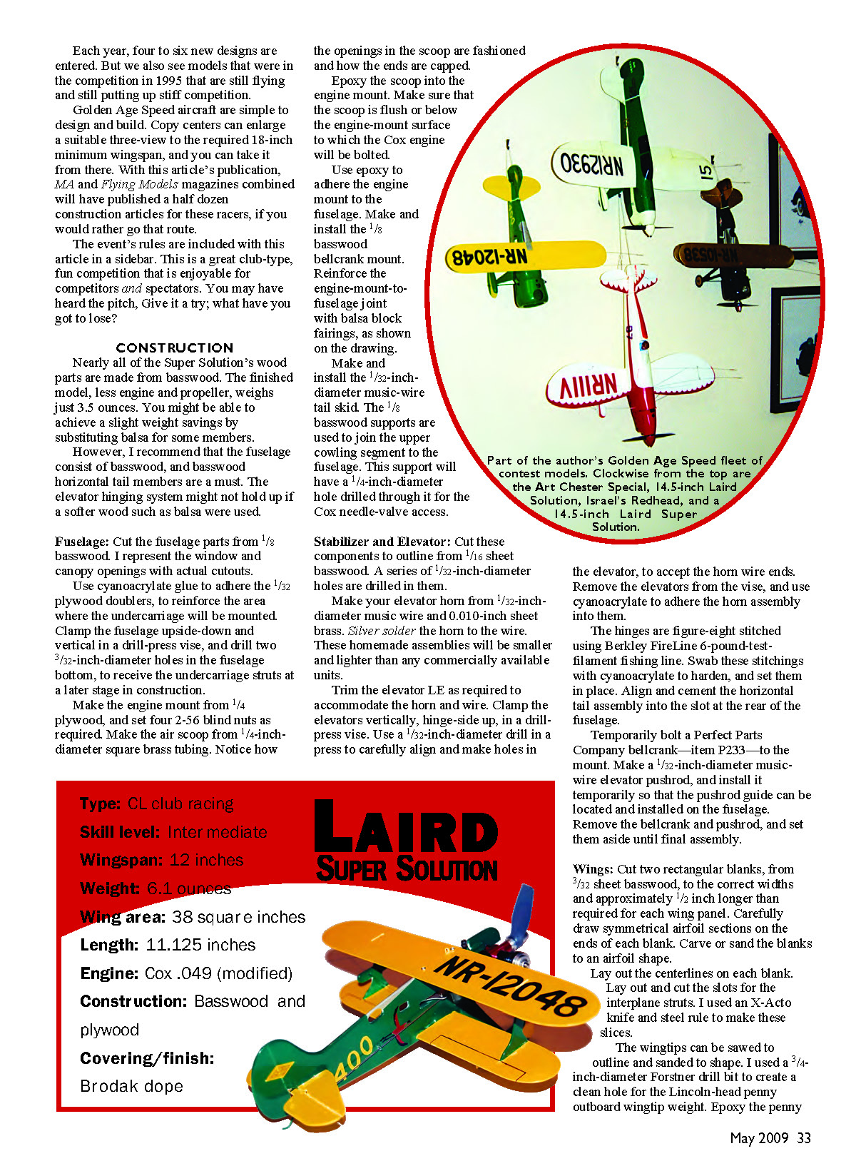
Each year, four to six new designs are entered. But we also see models that were in the competition in 1995 that are still flying and still putting up stiff competition.
Golden Age Speed aircraft are simple to design and build. Copy centers can enlarge a suitable three‑view to the required 18‑inch minimum wingspan, and you can take it from there. With this article's publication, MA and Flying Models magazines combined will have published a half dozen construction articles for these racers, if you would rather go that route.
This is a great club‑type, fun competition that is enjoyable for competitors and spectators. You may have heard the pitch: "Give it a try; what have you got to lose?"
CONSTRUCTION
Nearly all of the Super Solution's wood parts are made from basswood. The finished model, less engine and propeller, weighs just 3.5 ounces. You might achieve a slight weight savings by substituting balsa for some members; however, I recommend that the fuselage consist of basswood, and basswood horizontal tail members are a must. The elevator hinging system might not hold up if a softer wood such as balsa were used.
Fuselage
- Cut the fuselage parts from 1/8‑inch basswood. I represent the window and canopy openings with actual cutouts.
- Use cyanoacrylate glue to adhere 1/32‑inch plywood doublers to reinforce the area where the undercarriage will be mounted.
- Clamp the fuselage upside‑down and vertical in a drill‑press vise, and drill two 3/32‑inch‑diameter holes in the fuselage bottom to receive the undercarriage struts at a later stage.
- Make the engine mount from 1/4‑inch plywood, and set four 2‑56 blind nuts as required.
- Make the air scoop from 1/4‑inch‑square brass tubing. Notice how the openings in the scoop are fashioned and how the ends are capped.
- Epoxy the scoop into the engine mount. Make sure the scoop is flush with or below the engine‑mount surface to which the Cox engine will be bolted.
- Use epoxy to adhere the engine mount to the fuselage. Make and install the 1/8‑inch basswood bellcrank mount. Reinforce the engine‑mount‑to‑fuselage joint with balsa block fairings as shown on the drawing.
- Make and install the 1/32‑inch‑diameter music‑wire tail skid. The 1/8‑inch basswood supports are used to join the upper cowling segment to the fuselage. This support will have a 1/4‑inch‑diameter hole drilled through it for Cox needle‑valve access.
Stabilizer and Elevator
- Cut the stabilizer and elevator to outline from 1/16‑inch sheet basswood. Drill a series of 1/32‑inch‑diameter holes in them.
- Make the elevator horn from 1/32‑inch‑diameter music wire and 0.010‑inch sheet brass. Silver solder the horn to the wire. These homemade assemblies will be smaller and lighter than most commercial units.
- Trim the elevator leading edge as required to accommodate the horn and wire. Clamp the elevators vertically, hinge‑side up, in a drill‑press vise. Use a 1/32‑inch‑diameter drill in a press to carefully align and make holes in the elevator to accept the horn wire ends.
- Remove the elevators from the vise and use cyanoacrylate to adhere the horn assembly into them.
- The hinges are figure‑eight stitched using Berkley FireLine 6‑pound‑test filament fishing line. Swab these stitchings with cyanoacrylate to harden, and set them in place.
- Align and cement the horizontal tail assembly into the slot at the rear of the fuselage.
- Temporarily bolt a Perfect Parts Company bellcrank (item P233) to the mount. Make a 1/32‑inch‑diameter music‑wire elevator pushrod and install it temporarily so the pushrod guide can be located and installed on the fuselage. Remove the bellcrank and pushrod and set them aside until final assembly.
Wings
- Cut two rectangular blanks from 3/32‑inch sheet basswood to the correct widths and approximately 1/2 inch longer than required for each wing panel.
- Carefully draw symmetrical airfoil sections on the ends of each blank. Carve or sand the blanks to an airfoil shape.
- Lay out the centerlines on each blank. Lay out and cut the slots for the interplane struts. An X‑Acto knife and steel rule work well for these slices.
- Saw and sand the wingtips to shape. I used a 3/16‑inch‑diameter Forstner drill bit to create a clean hole for the Lincoln‑head penny outboard wingtip weight. Epoxy the penny in place, then fill and smooth the depressed area with Brodak Aeropoxy Lite.
- Sand all surfaces smooth and set the wings aside.
Interplane Struts
- Cut the interplane struts from 1/16‑inch plywood. Note that the port strut includes the control‑line guide.
- Dry‑fit the struts and the two wings together. Any trimming required to properly align the wings is much easier to achieve now than later during final assembly.
- Slide the lower wing into the slot in the fuselage, align it properly, and use cyanoacrylate to permanently affix it to the fuselage. I also use cyanoacrylate to adhere the interplane struts into the lower wing at this time. It is easier to paint these small parts when attached to a larger assembly.
Undercarriage
- Make the five parts for the undercarriage using the full‑size patterns on the drawings.
- Bind the assembly with 24‑gauge soft copper wire and solder the mating pairs of struts together.
- Bend the bound ends of these struts to the approximate angle and test‑fit them in the fuselage. Eyeball, tweak, and bend the struts so the axle will be properly aligned when the axle spreader bar is bound to the struts. The goal is for the model to sit level and for the axle to be at right angles to the fuselage.
- When satisfied, epoxy the struts into the fuselage and solder the bound joints at the axle. Slip small brass disks onto the axles and solder them to the wire struts. This provides additional gluing surface when you install the wheel pants.
Wheel Pants
- Make wheel pants from 3/8‑inch balsa cores with 1/64‑inch plywood sides. Carve the core to shape, use cyanoacrylate to adhere the plywood sides to the core, drill the 1/16‑inch‑diameter hole for the axle, and then use a Dremel tool to grind out the balsa core to accommodate the wheel.
- To install the pant and wheel on the axle, slip one side of the pant onto the axle cocked at an angle so you can slip on two #2 washers, the wheel, and then two more #2 washers, and push the axle through the outside of the pant.
- Solder a 1/16‑inch‑inside‑diameter brass grommet to the axle against the pant to retain the wheel. Epoxy anchors the wheel pant to the brass disks. Snip off any excess axle length.
- Fit triangular bits of 1/32‑inch plywood fairings between the struts and cover with 0.5‑ounce fiberglass.
- Two kinds of 1‑inch‑diameter wheels are available. One type has gray plastic hubs, and the other has clear plastic hubs. The clear hubs seem brittle, and failures in them caused me to prefer the gray plastic wheels.
Finishing and Painting
- It is easier to paint and apply trim to the model before the upper wing is permanently attached.
- I use Brodak dopes throughout the finishing process, thinned to at least a 1:1 ratio.
- Brush three coats of clear onto all components, wet‑ or dry‑sand between coats. Spray two coats of white primer and wet‑ or dry‑sand. Then spray three coats of yellow onto the wings, tail, wheel pants, and rear fuselage.
- Mask the Laird as required and then spray on three coats of green.
- Draw the registration numbers on the wings and rudder using a black Top Flite Panel Line Pen. Mask off and spray the red flamingos and lay on the black feathers with the Top Flite pen.
- Mask the canopy and spray with aluminum paint. Draw the aileron outlines with the Top Flite pen.
- After all trim is applied, spray on four coats of clear. Finish with rubbing compound and a wax job.
- The paint added approximately 1.1 ounces of weight to the model.
Final Assembly
- Create 0.015‑inch‑diameter music‑wire leadouts and attach them to the bellcrank. Bolt the bellcrank to its mount and permanently hook up the elevator pushrod.
- Epoxy the top wing to the fuselage and interplane struts. From experience, I use two small wood screws to reinforce the fuselage‑to‑wing joint.
- Bolt the engine and propeller to the firewall.
The brass ram air intake is the secret to good 1/2A engine performance; it’s shown epoxied to the 1/4‑inch plywood firewall. Assemble the model before finishing so you can test the control system. The wire loop in the center of the top wing is used to check the CG. The ready‑to‑fly prototype’s all‑up weight is 6.1 ounces; no ballast was required to properly balance the airplane.
Engine Stuff
Sport pilots may fly their models using any combination of 1/2A engine, propeller, and fuel that works for them. Competitors in Golden Age Speed must comply with the rules, but a racer's performance can be enhanced by a few suggestions.
- The engine of choice (if you can find one) is a Cox .049 Venom; however, a Cox .049 Black Widow will do.
- Substitute a metal backplate from one of the older, discontinued Cox engines for the Venom's plastic backplate. Ream the backplate and fuel‑tank openings with a 0.094‑inch‑diameter drill.
- You must use the standard (low compression) glow head, but you can remove the head gasket to raise the cylinder compression and improve engine performance.
- It is widely believed that a metal air scoop that rams air into the engine will improve performance, and several fliers have begun installing them on their aircraft.
- Cox Super Fuel (No. 550) is the fuel of choice.
- The propeller is specified in the rules: use a Cox 5 x 3 and balance it for best results.
Flying
Once these Golden Age racers are in the air, most will settle into a nice, groovy flight pattern. Although some are prone to tumbling if a sloppy landing is executed, most will glide smoothly to a two‑ or three‑bounce landing with a nice rollout.
Even if the airplanes tumble, they are tough. Except for a few scratches, they are likely to be none the worse for it.
Takeoffs deserve attention: these small aircraft are prone to nosing over on long takeoff runs. If they do, they will usually charge along with the propeller thrashing the pavement but eventually take to the air and complete an official flight. This doesn't do the propeller any favors, and performance does suffer, so takeoffs are a bit of an art.
You want sufficient up‑elevator to get the racer into the air quickly, but not so much that it induces a wingover followed by a dive into the turf. Most takeoffs are uneventful, and we rarely see an airplane totaled in a crash.
HAPPY ENDING
My little Laird was clocked at 58.59 mph, which was good for a third‑place trophy in the 2003 1/2A Golden Age Speed event. Tim Pansic's Mr. Smoothie aced us all with a 63.03 mph first place, and Alan van Artsdalen's Pesco Special was on Tim's heels at 62.98 mph.
My Laird flew with the nose yawed out enough to adversely affect its top speed. Yaw out can be reduced by moving the leadout‑wire guides forward. Do this carefully, in small increments, lest you overdo it and have a model that flies into the circle — that's a no‑no.
So, what's for next season? A Howard Pete? A Chester Goon? A Caudron? So many choices!
Frank W. Beatty 2608 Pontoon Rd. Granite City, IL 62040
Sources / Contacts
- Frank W. Beatty — (618) 931‑5436
- Perfect Parts Company — (410) 327‑3522, www.perfectpartscompany.com
- Brodak — (724) 966‑2726, www.brodak.com
- Top Flite — (800) 637‑7660, www.top‑flite.com
- Lafayette Esquadrille: Robert Arata, 561 Goldwood Dr., Ballwin, MO 63021 — (636) 391‑0272
Transcribed from original scans by AI. Minor OCR errors may remain.

