
Lancair IV-P
by Gus Morfis and Tom Fey
An RC propjet for fans of small electric models
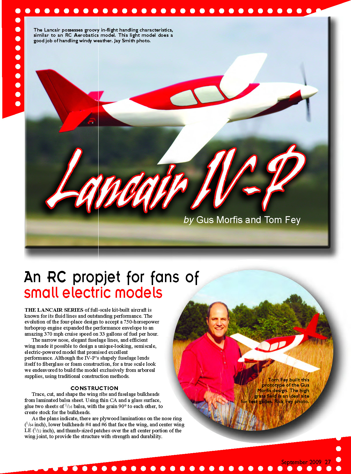
The Lancair series of full-scale kit-built aircraft is known for its fluid lines and outstanding performance. The evolution of the four-place design to accept a 750-horsepower turboprop engine expanded the performance envelope to an amazing 370 mph cruise speed on 33 gallons of fuel per hour.
The narrow nose, elegant fuselage lines, and efficient wing made it possible to design a unique-looking, semiscale, electric-powered model that promised excellent performance. Although the IV-P’s shapely fuselage lends itself to fiberglass or foam construction, for a true scale look we endeavored to build the model exclusively from wood supplies, using traditional construction methods.
Construction
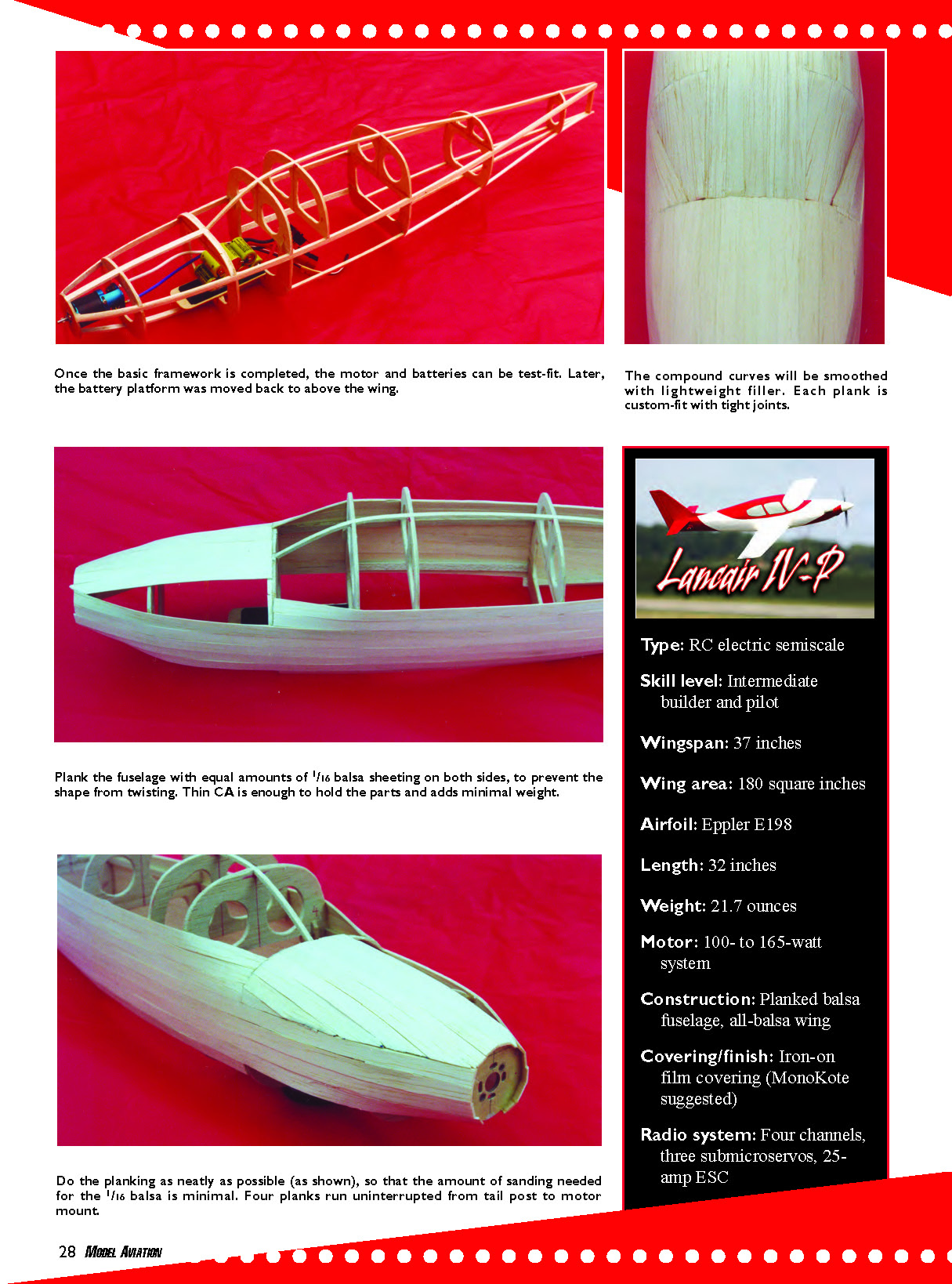
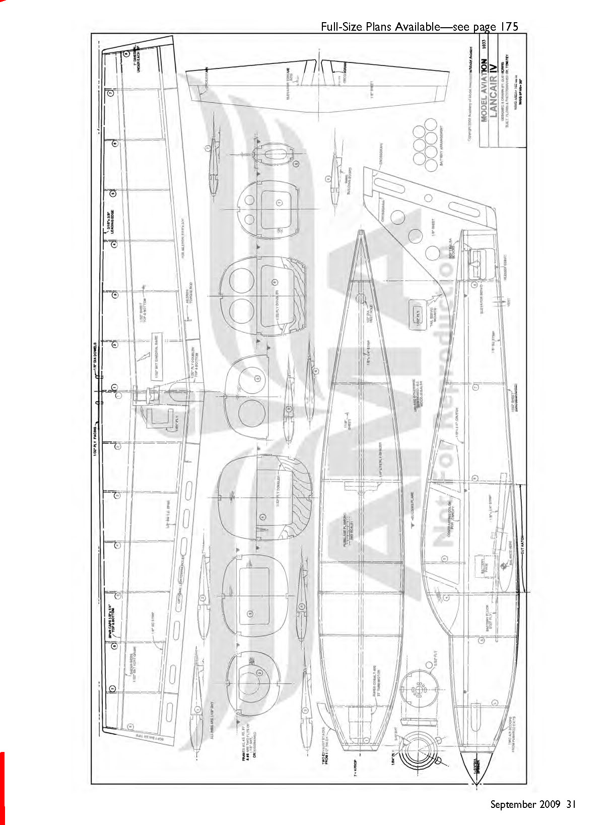
Trace, cut, and shape the wing ribs and fuselage bulkheads from laminated balsa sheet. Using thin CA and a glass surface, glue two sheets of 1/16-inch balsa, with the grain 90° to each other, to create stock for the bulkheads.
As the plans indicate, there are plywood laminations on the nose ring (1/64-inch), lower bulkheads #4 and #6 that face the wing, and center wing LE (1/32-inch), and thumb-sized patches over the aft center portion of the wing joint to provide the structure with strength and durability.
Fuselage: The lower fuselage is built upside-down over the plans, with the motor mount submerged slightly into the building board. Briefly soak the longerons in warm water to loosen them up so they will follow the plans contour. Carefully pin the longerons to the board over the plans. Use a scrap 1/8-inch balsa stick to act as a dummy tail post during fuselage construction, but do not glue it in place. The vertical stabilizer will eventually slide into this gap. Once dry, glue the bulkheads squarely against the longerons, followed by the wing crutch and lower longerons.
The lower longerons bend aggressively toward the motor mount and must be preformed wet, allowed to dry in place, and then glued. Use epoxy for the motor mount and aliphatic glue for the rest of the bulkheads. Nose-side perimeters of bulkheads #2 and #3 and aft-facing perimeter #6 have thin strips of soft 1/8-inch-square balsa glued to them to provide increased adhesion area for balsa planking. Cover the upward-facing surface of the battery floor with hook-and-loop fastener, and glue it in place with epoxy. Once dry, remove the lower fuselage from the board and glue the upper bulkheads and dorsal longeron in place.
The fuselage framework is spindly at this point, so be careful as you use a long sanding bar to gently bevel the bulkheads and longerons to the fuselage’s curves, leaving smooth, radiused surfaces to which the planking will adhere.
Planking a fuselage takes time and effort, but the end product is a work of art. Wear gloves or barrier cream; you’ll get CA on your skin during this process. Employ a balsa stripper shimmed to provide an approximate 60° angle on the edge. Cut several dozen 7/16-inch-wide strips from 1/16-inch balsa sheet.
Using thin CA and working from tail to nose, glue the first strip midway over the fuselage longeron. Carefully align the second strip tightly and close to the first strip, working slowly from tail to nose, stretching it ever so slightly, placing it firmly against the bulkheads. Apply micro-drops of thin CA every 1/2 inch or so to glue the strips to each other and to the bulkheads.
Apply two strips on the starboard side and two strips on the port side to prevent warping the framework. Use the CA sparingly, and occasionally go back from the inside of the fuselage to glue loose planking, and double-glue all strips to the bulkheads.
Continual strips can run on the sides from the tail to the motor mount, using the water-soak/prefitting trick to help shape the pieces where necessary. The planking strips will eventually be unable to make the sharp, twisting bend toward the motor mount. This is expected. The remaining open areas will be planked on the top of the nose from bulkhead #3 to the motor mount, and eventually on the bottom of the nose from bulkhead #4 to the motor mount. This requires custom fitting, patience, a sanding block, and trial and error, but it is highly rewarding.
Plank the top of the nose starting at the center and working out to the sides, eventually custom-fitting strips to fill the gaps. Wait to plank the lower nose and lower aft fuselage until after you have mounted the wing.
Five continual strips can be planked down the center of the upper fuselage between bulkhead #8 and bulkhead #3, but eventually the compound curves become too severe. The upper empennage is planked with individually fitted pieces, and the windshield edges are formed from triangle-shaped balsa-sheet inserts.
When you have completed the planking, gently sand the high spots with 400-grit paper to yield a smooth finish. Fill large gaps with scrap balsa strips using sandable aliphatic glue, and remedy imperfect contours and small gaps with lightweight spackling compound and more sanding. Don’t sand too much, because the sheeting is already relatively thin.
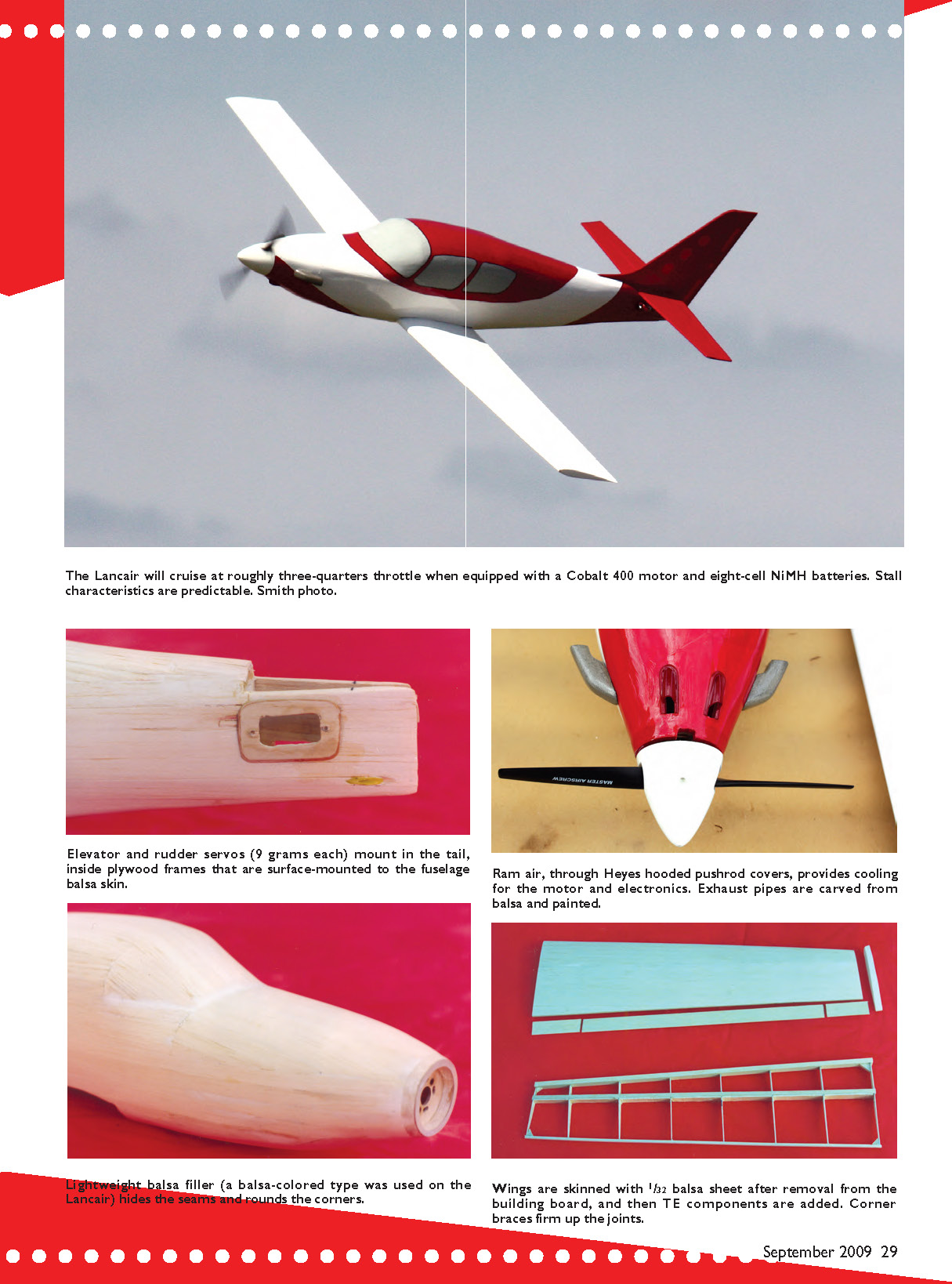
Size and shape the 1/32-inch plywood doublers for the rudder and elevator to the servos you intend to use, glue them onto the aft fuselage as shown, and use a rotary tool to remove the balsa sheet from the center of the cutout. Make sure that the cutouts and servo screws do not cut into the fuselage longerons.
I used Ernst pushrod exits as cooling intakes on the lower nose and made an appropriately sized cooling-air exit hole in the ventral aft fuselage.
Mount the motor, propeller, and spinner into the fuselage, and use 1/4-inch balsa sheet with a 1/64-inch plywood lamination to make an oversize nose ring. With the plywood facing the spinner, sand the nose ring to smoothly fair the fuselage to the spinner. Cut a gap in the lower nose ring to allow access to the propeller-adapter setscrew.
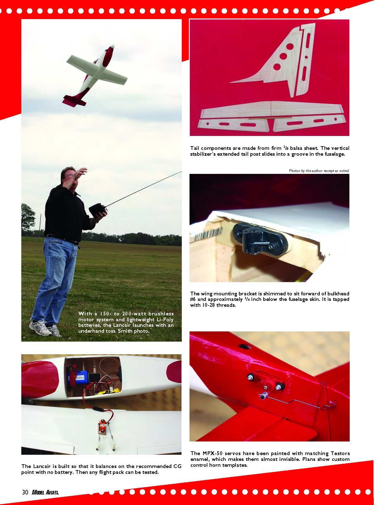
Employ a light-plywood spacer to position the aft wing mount, as plans show, and bolt the mount to bulkhead #6, making sure it is 1/8–1/4 inch below fuselage skin level to allow the wing trailing edge to be flush with the lower aft fuselage skins. Use scrap 1/32-inch plywood sheet on the aft side of bulkhead #6 to form a strong base for the mount nuts and washers.
Wing
The wing construction is straightforward, using the dihedral gauge to cant the top of each #1 rib out by 3°, giving 6° of final dihedral. The ribs must sit squarely over the lower spar and the ventral skegs must sit hard against the board to give the wing ribs proper angle and washout. You will trim off the skegs before you apply the lower sheeting.
Use diagonal braces to strengthen the butt-joint corners where the LE and TE meet ribs #1 and #8. Add the small balsa doublers to reinforce the hinge areas. Minimally and gently smooth the ribs with a sanding bar, and sheet the wing with 1/32-inch balsa. Add the wingtips made from soft balsa blocks.
The aileron rods are fitted into grooves cut into the unfinished wing’s trailing edge, and then the TE is fitted and glued in place. Position the aileron servo off center to preserve the center ribs’ strength, and set it high on scrap balsa/plywood pedestals to prevent the servo screws from penetrating the wing spar or the servo base from sticking through the bottom of the wing. Attach the ailerons with Robart 1/2A pin hinges, and seal the gap on the top surface with strips of covering.
Sand the wing and ailerons gently and minimally (remember that the wing skins are thin) to obtain a smooth contour. Epoxy the wing halves together using the main spars as a guide for alignment. I used 1.5-inch-long, 1/4-inch-wide strips of 1/32-inch plywood to laminate the upper and lower spar joints.
Adhere the plywood doublers on the aft wing joint, sand the centerline face of the LE square, and epoxy the fuselage-wide 1/32-inch plywood sheet to the LE. Glue triangular hard-balsa shims behind the LE plywood facing to add some structure to receive the wing-mounting dowels.
Carefully sand the fuselage sides over the wing crutch to achieve a wing contour with minimal gap between the top wing surface and the fuselage side at the wing crutch. Align the wing centerline joint with the centers of the lower fuselage longerons.
Using the wing-mount hole as a guide, mark the wing-bolt position from inside the fuselage. Drill the appropriate hole through the wing, and bolt the wing into the fuselage. Shim or grind the mount as required to ensure that the wing sits on the mounting bracket and is not crushing the fuselage sides or wing surface.
Double-check the LE centerline with the fuselage longeron and make sure that the wing sits symmetrically in the saddle by comparing it to a dummy horizontal stabilizer that is temporarily glued across the stern longerons.
Once satisfied with the alignment, use an extra-long 1/8-inch-diameter drill bit to bore the first hole squarely through bulkhead #4 and into the wing. Put a temporary dowel through hole #1 to hold the wing in place, double-check alignment, and drill hole #2.
Remove the wing and glue 1/8-inch-diameter hardwood dowels into the holes. Toughen the peg holes in bulkhead #4 with thin CA, and then ream them clean.
Now you can plank the lower nose fuselage and sheet the lower empennage with cross-grain balsa. Build up the lower wing fairing under the fuselage using a few 1/4-inch-wide by 1/16-inch-thick balsa strips glued to the lower wing surface. Sand these pieces flat before gluing a cross-grain balsa filler on top of that. Smoothly fair and/or fill the underside of the wing into the lower fuselage.
Final Assembly
Cut the tail feathers from 1/8-inch balsa sheet using a 1/8-inch-square by 3-inch-long hardwood stick or piano-wire joiner to connect the elevator halves. I used Granite State gapless iron-on hinge for the elevator and rudder, with handmade 1/16-inch plywood horns epoxied into the moving surfaces. The lower vertical stabilizer’s leading edge slides into the groove in the aft end of the fuselage.
The choice of power system and batteries will dictate where you mount the batteries. There is plenty of room inside the fuselage to mount the electrical components, including elevator and rudder servos, if desired.
For the prototype, the relatively heavy Cobalt motor, propeller, and spinner mounted so far in front of the CG that it necessitated placing the servos in the far end of the tail to avoid dreaded ballast.
Covering
We covered the prototype in white and red MonoKote. The windows were painted on with gray acrylic paint outlined in black. Painting mistakes are easy to remedy with a wipe of denatured alcohol.
The turbine exhaust shrouds are hand-carved scrap balsa that was painted and glued onto the fuselage with canopy glue. Although the IV-P is a civil aircraft, the red tail honors the Tuskegee Airmen.
Flying
With the CG and control throws set per plans, with one click of up-elevator the Lancair can be hand-launched with a moderate overhead throw at the horizon. It powers out of the launch well and is responsive in all axes.
The wing provides excellent inverted and outside performance. The prototype demonstrated a nice rate of speed, but a modern brushless power system would turn this airplane into a long-duration screamer.
The propjet should be flown at a shallow angle into a landing. You should wait to attempt full-stall landings and low-level aerobatics until you are accustomed to the model’s performance envelope, wing loading, and stall speed.
Even though the IV-P takes builder’s skill and more time than some other projects, the payoffs are an expansion of your skill set and a sleek, distinctive, high-performance airplane that is probably rare to see at your airfield.
Gus Morfis [email protected]
Tom Fey [email protected]
MA Flies the Propjet
We were thrilled to accept the Lancair project from Gus and Tom. During the discussion, the need for in-flight photos came up; the solution offered was to ship the prototype to AMA Headquarters. We accepted, of course.
We flew the model exactly as described in the preceding and found the performance reports to be spot on. We had a blast flying the model with the brushed-motor system and NiMH batteries. Call us spoiled, but we couldn’t help but have total confidence that a modern brushless system and Li-Poly batteries would pump this propjet even better into the sleek speedster that its full-scale heritage boasted.
Looking at what we had on hand, a six-pole, 2600 Kv inrunner helicopter motor was exchanged for the Cobalt 400; it was practically the same weight and size. The ESC was exchanged for a brushless type that included auto-detect programming with Li-Poly cutoff protocols. We kept the same 7x4 Master Airscrew propeller and Du-Bro spinner.
The well-thought-out prototype flew with the batteries right over the CG; therefore, choosing the appropriate Li-Poly was simply a matter of accommodating the expected motor demand.
We settled on a 7.4-volt power source, which tested on the bench to handle roughly a 16-amp load. On hand was a 2400 mAh 10C Li-Poly battery that weighed roughly half of the old 8.4-volt NiMH pack. We dropped close to 2 ounces overall and gained 50–65 watts of power. With smiles all around, it was time to fly again.
The Lancair could be launched with either an overhand or underhand toss. A headwind actually helps a lot.
The extra power and lighter weight did wonders for the friendly model. Pylon turns were comfortable, as were any power-hungry maneuver from level flight. Shedding the bit of weight permitted a landing that simulated a flop into the grass rather than a skid.
Our final thoughts were that the Lancair would suit any builder, no matter what power choice was available; later changes are a matter of plug-and-play. If a smooth runway is at hand, the IV-P could be modified for fixed (removable) landing gear.
Michael Ramsey [email protected]
Sources
- Ernst Manufacturing — (503) 668-5597 — www.ernstmfg.com
- Robart — (630) 584-7616 — www.robart.com
- Master Airscrew/Windsor Propeller — (916) 631-8385 — www.masterairscrew.com
- Du-Bro — (800) 848-9411 — www.dubro.com
Transcribed from original scans by AI. Minor OCR errors may remain.

