
Large-Scale Floats
Observations from an award-winning designer
by Lawrence Klingberg
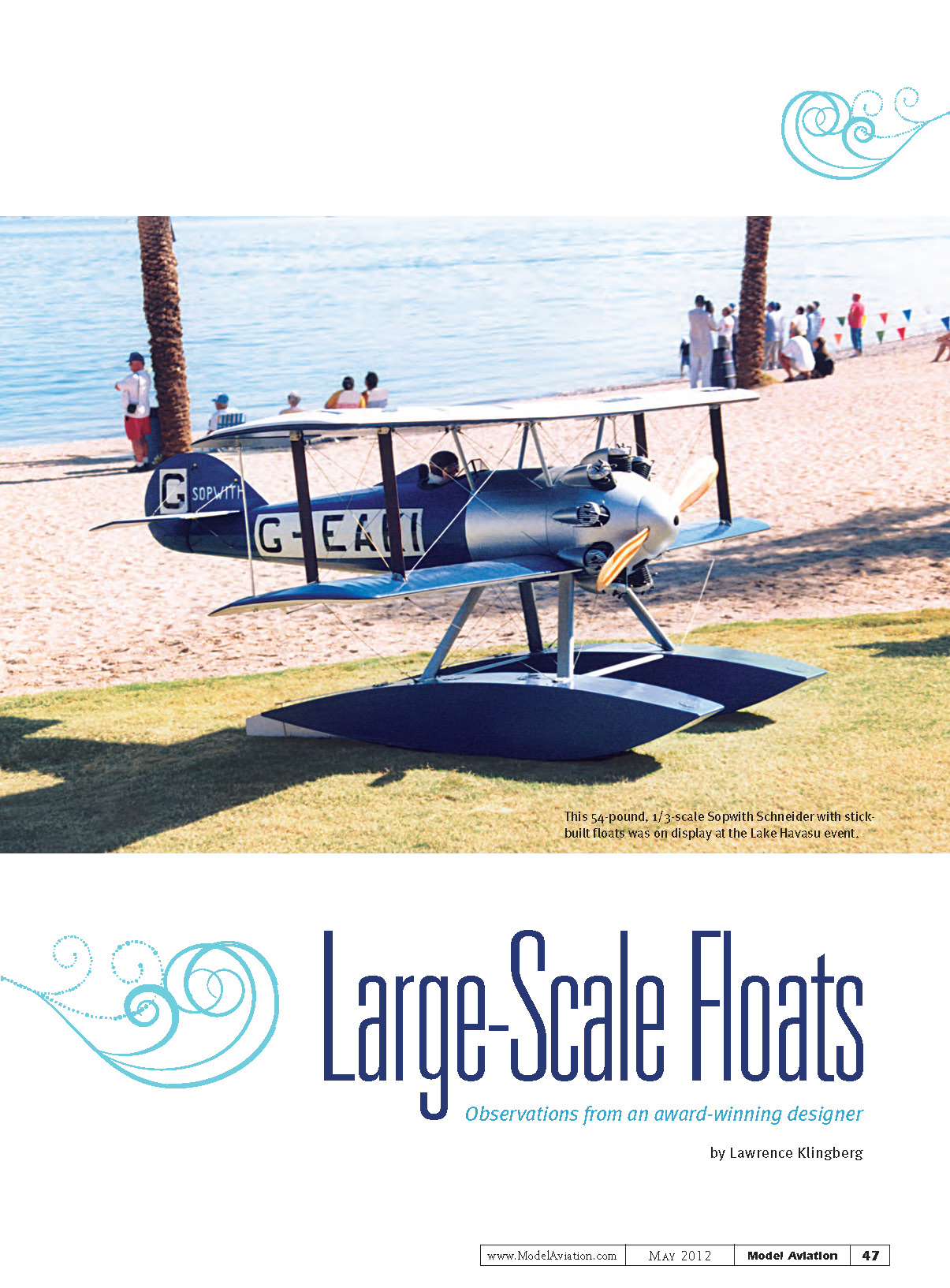
In 1989 I was fortunate to attend the first Schneider Cup Giant Scale Re-Enactment at Lake Havasu City, Arizona. The event was the brainchild of Bob and Katie Martin, and the Desert Hawks Radio Control Club members helped put on a spectacular water-flying event then and in subsequent years.
After observing this and other events, I decided it was time to start building some large seaplanes of my own. My observations led to a few conclusions about what kinds of seaplanes have the best chance for competition and survival in a Schneider Cup–class contest.
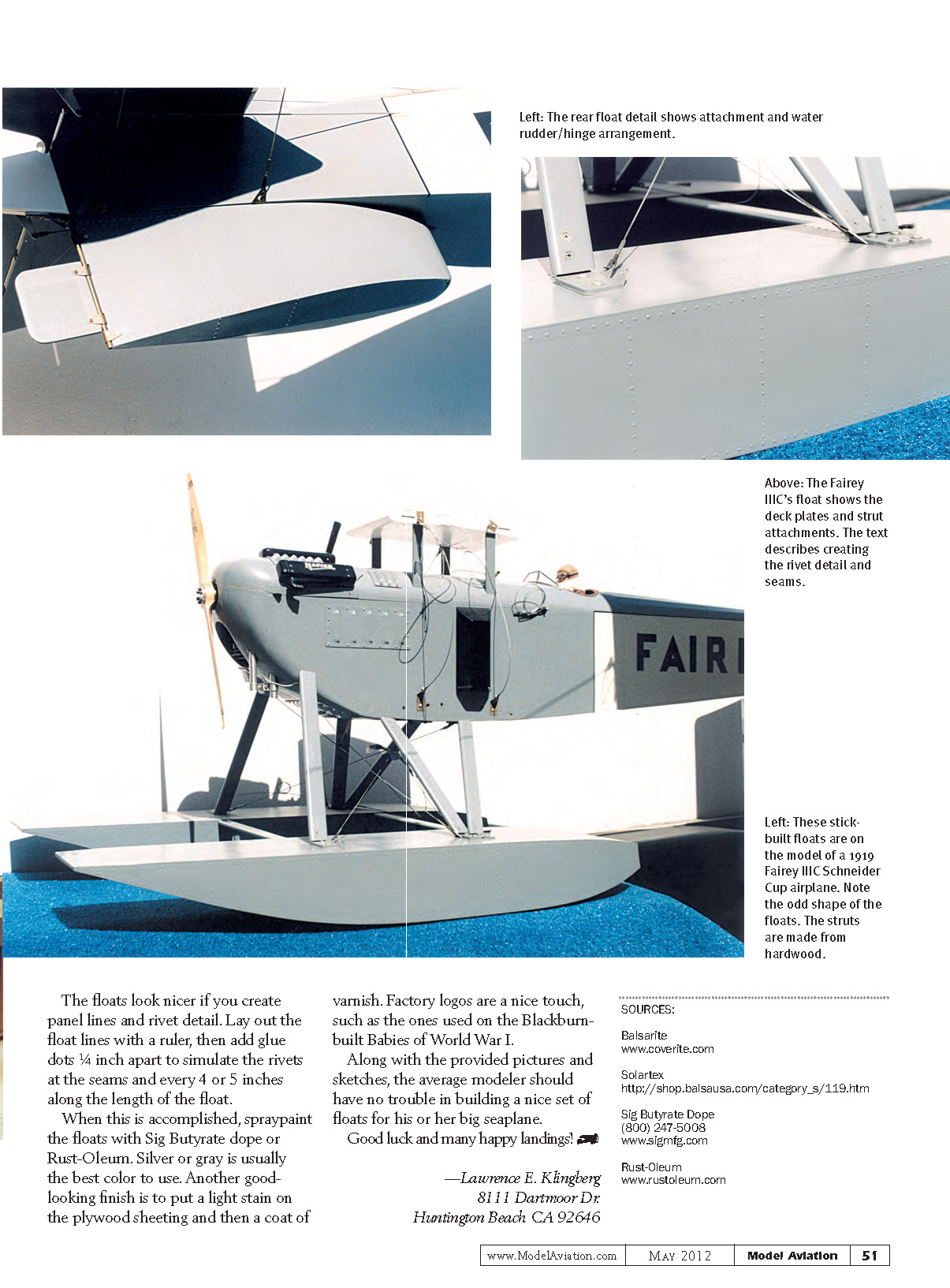
I felt that a biplane on floats, sitting high off the water with sufficient clearance for the propeller, was the best choice for success. Most of the early airplanes had undercambered wings, which created substantial lift. My first choice to build for the Schneider was a 1919 British Fairey IIIC biplane, registered as G-EALQ, at 1/4 scale.
It took roughly a year to draw the plans and finish this large project for the 1992 event. The airplane “flew right off” the drawing board. Since then I have built three more 1/3-scale aircraft: a Sopwith Schneider (1919 biplane, G-EAKI) and two 1/3-scale Sopwith Pups, and I built floats for all of them.
The purpose of this article is to show how floats can be constructed and attached to large-scale airplanes. Floats of this size must be made as strong and as waterproof as possible.
Types of Floats
I'll describe two methods I have used to build large floats and what has worked best for me:
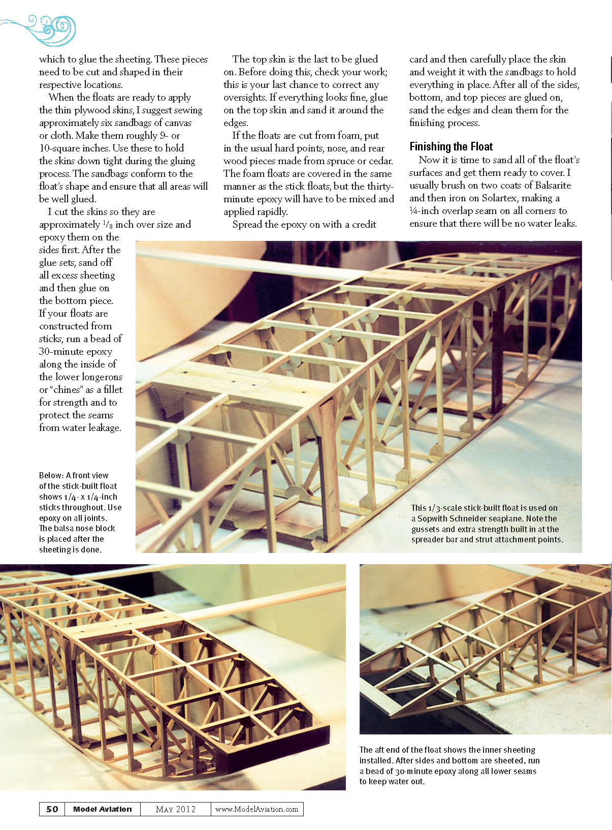
- Built-up (stick) construction: These floats are constructed much like a fuselage using 1/4 x 1/4-inch balsa or spruce pieces with gussets at each joint to hold everything together.
- Foam construction: Foam floats are cut using the hot-wire method. Temporary templates are fastened to the foam to guide the hot wire to conform to the outline of the float. This method is much less time-consuming.
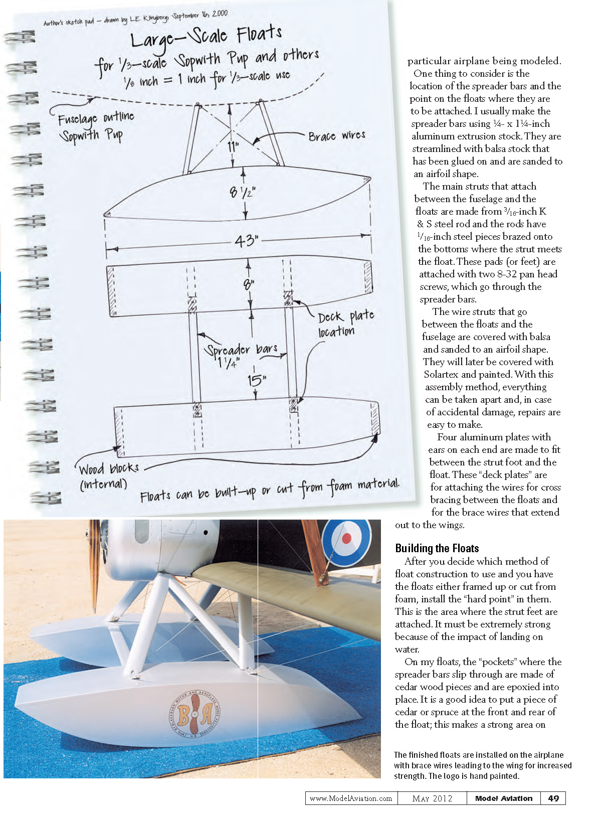
Whatever type you choose, the first step is to design the side and top views. Shapes for early floats can usually be found in three-views or books about the particular airplane being modeled. Consider the location of the spreader bars and the points on the floats where they will be attached.
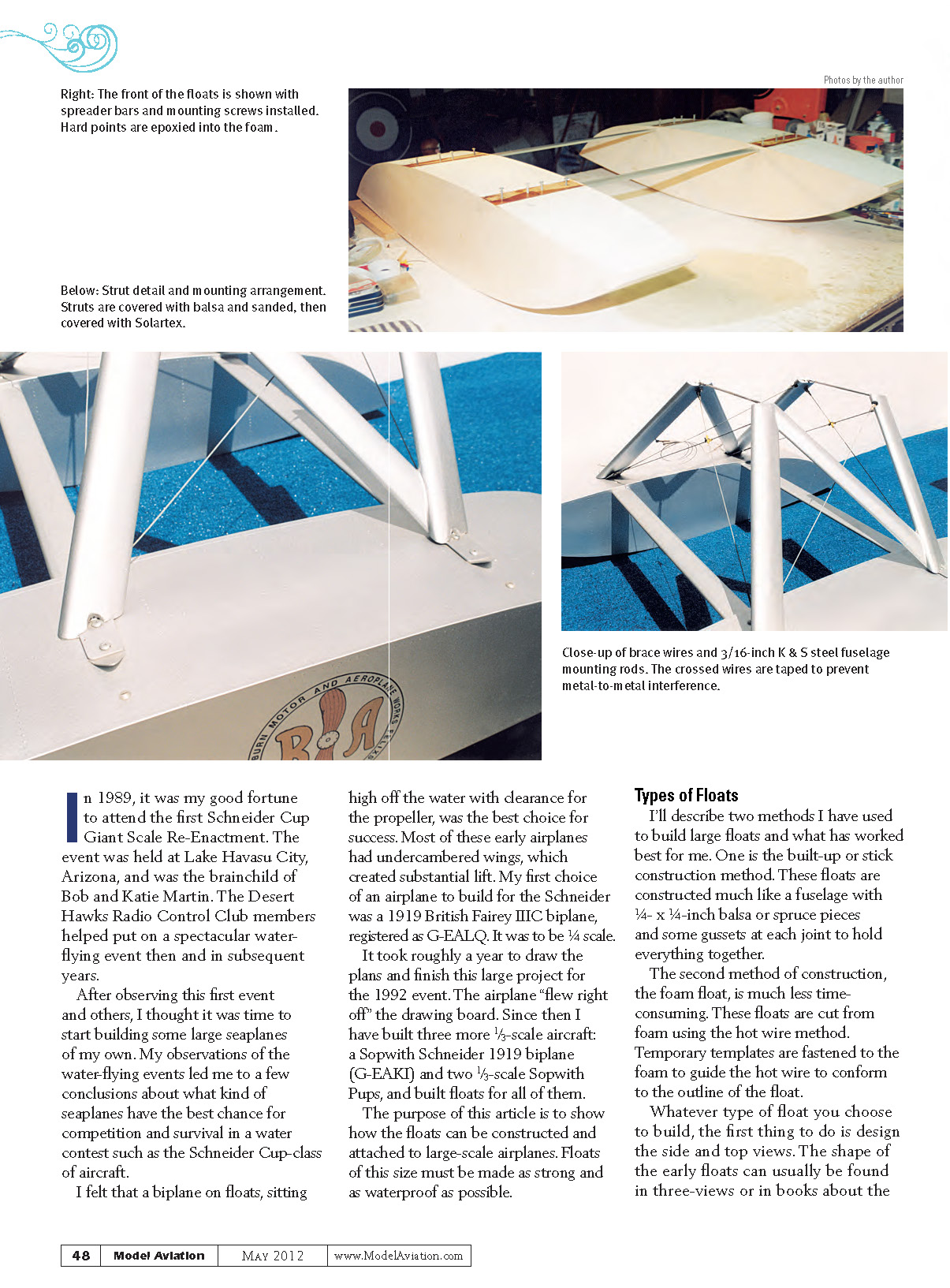
I usually make the spreader bars from 1/4 x 1 1/4-inch aluminum extrusion stock. They are faired with balsa glued on and sanded to an airfoil shape. The main struts that attach between the fuselage and the floats are made from 3/16-inch K & S steel rod; 1/16-inch steel pieces are brazed onto the bottoms where the strut meets the float. These pads (or feet) are attached with two 8-32 pan head screws, which pass through the spreader bars. The wire struts that run between the floats and the fuselage are covered with balsa and sanded to an airfoil shape; they are later covered with Solartex and painted. With this assembly method, everything can be taken apart in case of accident.
Four aluminum plates with ears on each end are made to fit between the strut foot and the float. These "deck plates" are for attaching the wires for cross-bracing between the floats and for the brace wires that extend out to the wings.
Building the Floats
After you decide which method of float construction to use and you have the floats either framed up or cut from foam, install the hard points where the strut feet are attached. This area must be extremely strong because of the impact of landing on water.
On my floats, the pockets where the spreader bars slip through are made of cedar pieces and epoxied into place. It is a good idea to put a piece of cedar or spruce at the front and rear of the float; this provides a strong area on which to glue the sheeting. Cut and shape these pieces to fit their respective locations.
When the floats are ready for thin plywood skins, prepare approximately six sandbags of canvas or cloth, roughly 9 or 10 square inches each. Use these to hold the skins down tight during the gluing process. The sandbags conform to the float's shape and ensure good adhesion.
Cut the skins approximately 1/8 inch oversize and epoxy them to the sides first. After the glue sets, sand off excess sheeting and then glue on the bottom piece. If your floats are constructed from sticks, run a bead of 30-minute epoxy along the inside of the lower longerons (chines) as a fillet for strength and to help prevent water leakage at the seams.
The top skin is the last to be glued on. Before doing this, check your work carefully—this is your last chance to correct any oversights. If everything looks fine, glue on the top skin and sand it around the edges.
If the floats are cut from foam, install the usual hard points, nose, and rear wood pieces made from spruce or cedar. Cover the foam floats in the same manner as the stick floats, but mix and apply the 30-minute epoxy rapidly. Spread the epoxy with a credit card, carefully place the skin, and weight it with the sandbags to hold everything in place. After all sides, bottom, and top pieces are glued on, sand the edges and prepare them for finishing.
Finishing the Float
Sand all float surfaces smooth and get them ready to cover. I usually brush on two coats of Balsarite, then iron on Solartex, making a 1/4-inch overlap seam on all corners to ensure there will be no water leaks.
To add detail, create panel lines and rivet simulation. Lay out the lines with a ruler, then add glue dots 1/4 inch apart to simulate rivets at seams and every 4 or 5 inches along the length of the float.
When this is accomplished, spray-paint the floats with Sig Butyrate dope or Rust-Oleum. Silver or gray is usually best. Another attractive finish is a light stain on the plywood sheeting followed by a coat of varnish. Factory logos are a nice touch, such as those used on Blackburn-built Baby seaplanes of World War I.
Along with the provided pictures and sketches, the average modeler should have no trouble building a nice set of floats for his or her big seaplane.
Good luck and many happy landings!
—Lawrence E. Klingberg 8111 Dartmoor Dr. Huntington Beach, CA 92646
SOURCES
- Balsarite
- Solartex
http://shop.balsausa.com/category_s/119.htm
- Sig Butyrate Dope
(800) 247-5008 www.sigmfg.com
- Rust-Oleum
Transcribed from original scans by AI. Minor OCR errors may remain.

