
Let's Talk About: Airplane Design
Brad Powers
Introduction
In the April 1980 issue of MA, in an article entitled "Let's Talk About the CG," we discussed the subject of static longitudinal stability. Whether one flies models or full‑size aircraft, understanding this subject is essential for satisfactory performance — and safety. An unstable airplane is difficult, if not impossible, to control. Thus it poses a threat to bystanders in the case of models and can be life‑threatening to the pilot of a full‑size plane.
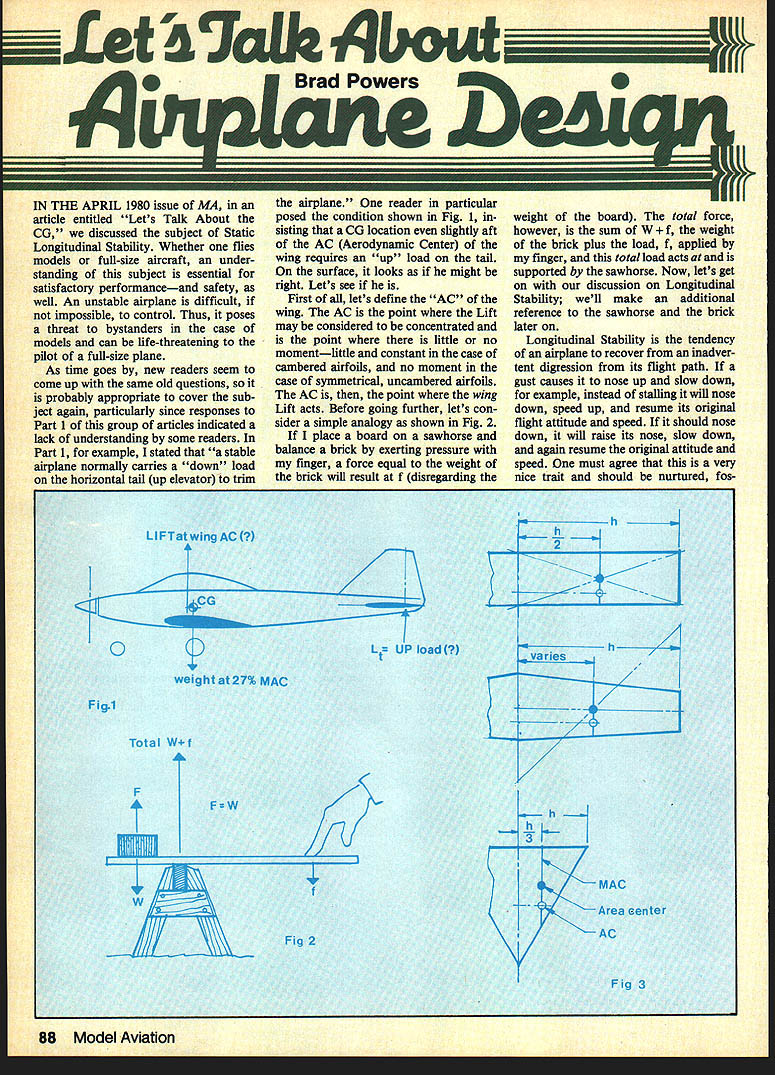
As new readers continue to ask the same questions, it is appropriate to cover the subject again. Responses to Part 1 showed a lack of understanding by some readers. In Part 1 I stated that "a stable airplane normally carries a 'down' load on the horizontal tail (up elevator) to trim the airplane." One reader argued that a CG slightly aft of the wing AC would require an "up" load on the tail. At first glance that seems plausible; let's examine whether it is correct.
Outline
- Define the Aerodynamic Center (AC) of the wing
- Use a simple analogy to illustrate forces and moments
- Define longitudinal stability and its determinants
- Discuss Neutral Point (N), stability margin, and trim moments
- Explain stable, neutral, and unstable conditions
- Note modern control systems and closing remarks
Aerodynamic Center (AC)
The Aerodynamic Center (AC) of the wing is the point where the wing lift may be considered concentrated and where there is little or no pitching moment:
- For cambered airfoils: small, nearly constant moment.
- For symmetrical (uncambered) airfoils: no moment.
The AC is essentially the point about which wing lift acts.
A Simple Analogy
Consider a board balanced on a sawhorse with a brick on the board. If you press on the board to balance the brick, a force equal to the brick's weight appears at your finger. Disregarding the board's weight, the total force supported by the sawhorse is the sum of the brick's weight plus your applied load. The total load acts at the sawhorse. We will refer back to this sawhorse/brick analogy when discussing trim moments and the Neutral Point.
Longitudinal Stability — Definition
Longitudinal stability is the tendency of an airplane to recover from an inadvertent deviation from its flight path. Examples:
- If a gust causes the nose to rise and the airplane slows, a stable airplane will nose down, speed up, and resume its original attitude and speed.
- If the nose drops, a stable airplane will raise its nose, slow down, and return to the original condition.
This automatic recovery is a desirable trait and should be preserved in design.
Determinants of Longitudinal Stability
Two primary factors determine longitudinal stability:
- Decalage (the angular difference in incidence between the forward and aft lifting surfaces)
- CG location relative to the Aerodynamic Center of the whole airplane (Neutral Point, N)
Decalage
Decalage is the angular difference in setting (incidence) between the forward surface (usually the wing) and the aft surface (usually the horizontal tail). The term roughly translates from French to mean "wedge‑shaped"; another name is longitudinal dihedral.
Two reasons for decalage:
- The forward surface is set at a higher angle of attack and will stall first, producing a diving moment that aids recovery from stall (applies to tailless, conventional, and canard types).
- The aft surface trims the airplane by being set to the desired angle of attack to maintain speed (in a canard, the forward surface trims).
The need for a trimming surface was identified by Alphonse Pénaud in the 19th century.
CG Location and the Neutral Point (N)
- The Aerodynamic Center of the whole airplane is generally called the Neutral Point (N).
- A longitudinally stable airplane must have the CG forward of N.
- The distance the CG is ahead of N is the stability margin, usually expressed as a percentage of the Mean Aerodynamic Chord (MAC).
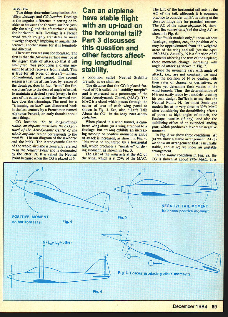
- The MAC passes through the center area of the wing panel.
Typical practical notes:
- For many scale models, after accounting for fuselage, power, nacelles, and landing gear effects, N is near 30% MAC.
- A stability margin of about 5% MAC is a good rule, especially for beginners. A margin of 3% is workable but less forgiving.
Moments, Wind Tunnel Observations, and Trim
Wind tunnel tests of a cambered wing alone (wing attached to fuselage, no tail) show an increasing nose‑up pitching moment as angle of attack increases. This positive (nose‑up) moment must be countered by the horizontal tail, which produces a negative (nose‑down) moment.
- Wing lift acts near the wing AC (about 25% MAC for many wings).
- Tail lift acts near the tail AC (practically often treated as acting at the elevator hinge line).
- The Neutral Point (AC of the whole airplane) lies somewhat aft of the wing AC because of the tail's contribution to moments.
Because moments vary with angle of attack, the Neutral Point is found by examining the rates of change (derivatives) of moments or by wind tunnel measurement. For modelers, a practical approximation for many conventional configurations is N ≈ 30% MAC.
Stable, Neutral, and Unstable Conditions
Referencing CG position relative to N:
Stable (CG forward of N)
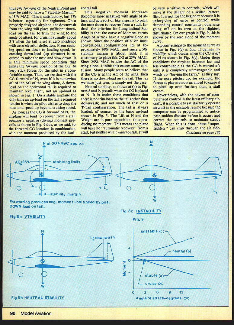
- The moment curve (moment vs. angle of attack) has a negative slope.
- Example: CG at 27% MAC with N at 30% MAC → stability margin 3% MAC (5% is preferable).
- On a properly designed airplane, wing downwash will place enough down‑load on the tail to trim the wing for cruise when the tail incidence is set to zero and elevator deflection is zero.
- From cruise down to landing speeds, increasing down‑load (more up elevator) is required to raise the nose and slow down.
- Even if CG is aft of the wing AC, with CG forward of N the tail typically carries a down‑load in level flight — contrary to the misconception that being at the wing AC implies no tail down‑load.
Neutral (CG at N)
- The moment curve has zero slope.
- There is essentially no trim moment from the CG vs. aerocenters (aside from downwash effects).
- The airplane has no automatic recovery from a disturbance but is not inherently divergent; it is very sensitive to controls.
- Preferred by skilled pattern or aerobatic pilots who want sensitive handling; not recommended for beginners.
Unstable (CG aft of N)
- The moment curve has a positive slope.
- Small disturbances grow: if the nose pitches up, forces act to pitch it up further, leading to loss of control and possible crash.
- Modern military aircraft sometimes operate in the unstable regime using computerized fly‑by‑wire controls that actively stabilize the aircraft.
Practical Trim Considerations
- Whether the horizontal tail carries a down‑load or up‑load depends on the overall trim and flight condition, not on CG position relative to the wing AC alone.
- Stability is governed by the CG location relative to the Neutral Point and by decalage.
- When designing or trimming a model, use the sawhorse/brick analogy: the moments about the support must balance for equilibrium, and the distribution of moments determines the dynamic response.
Modern Control Systems
With advanced computerized control, modern fighters can be designed to be statically unstable for maneuverability; the computer continuously corrects control surfaces to maintain steady flight. When such control systems become available for models, stability and CG location concerns will be reduced for modelers.
Closing and Contact
Questions and comments may be addressed to: Brad Powers 5470 Castle Hill Dr. San Diego, CA 92109
See also "Let's Talk About CG," May 1980 Model Aviation for related discussion.
Transcribed from original scans by AI. Minor OCR errors may remain.

