
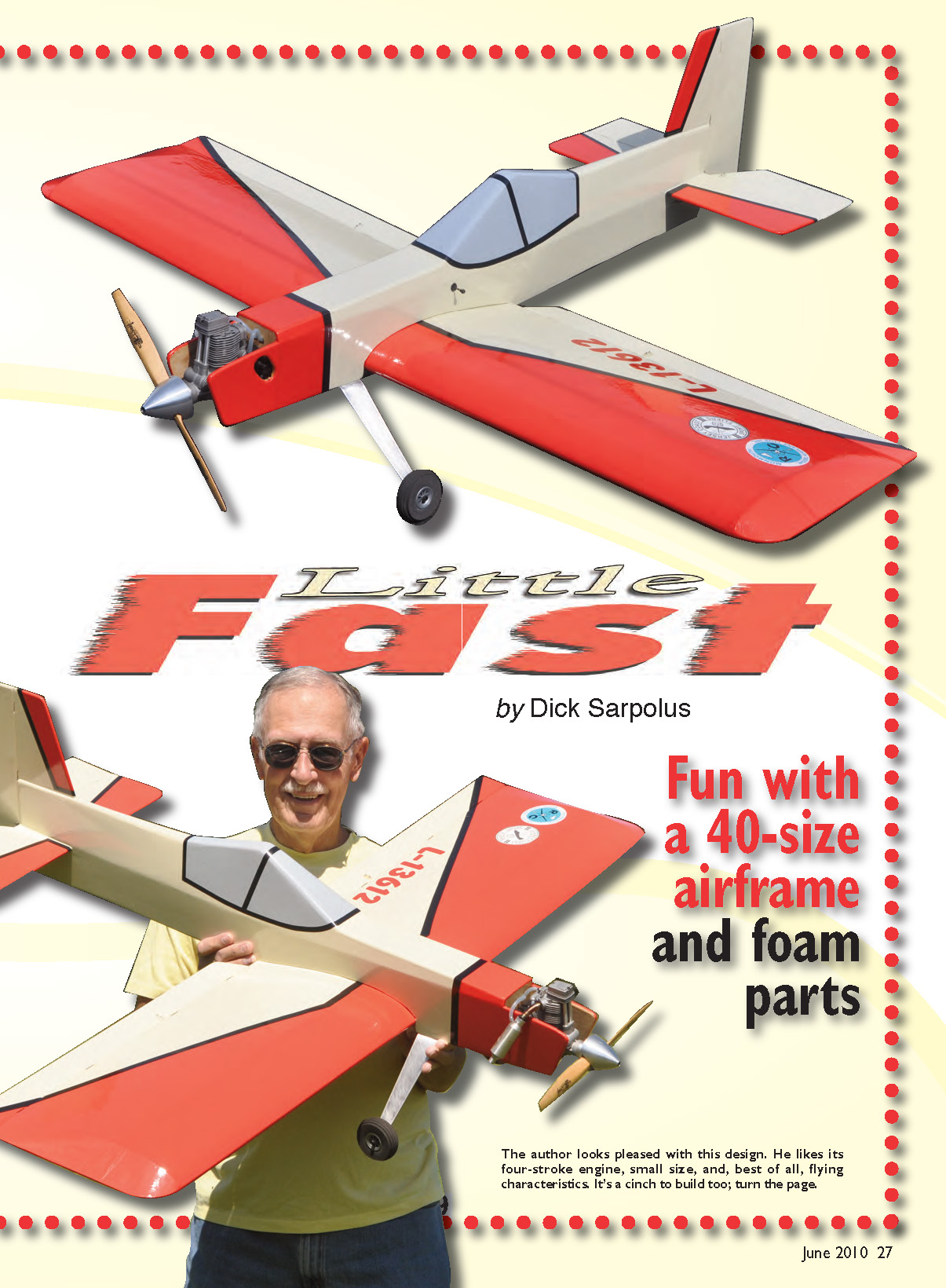
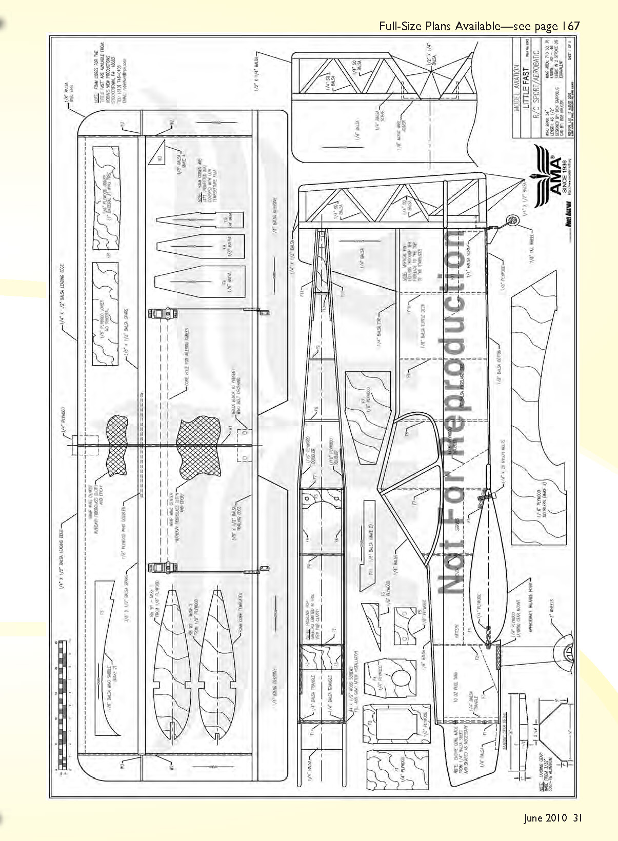

Little Fast
by Dick Sarpolus
Again, I found a reason/excuse to build a new model. A Magnum .70 four-stroke that I had bought for another project didn't work out, so it was available. The engine was broken in and had been flown a few times, with good performance. I figured that a .46 two-stroke–size airframe for aerobatics, sport, and fun would be a good project.
I know a bunch of ARFs on the market would work fine for this project. But regardless of the time, work, and money involved, I like to build my aircraft from scratch. I like to spend time in the workshop, making sawdust and wood chips. If you don't like to build, ARFs are great. However, I consider the workshop time a good part of this hobby.
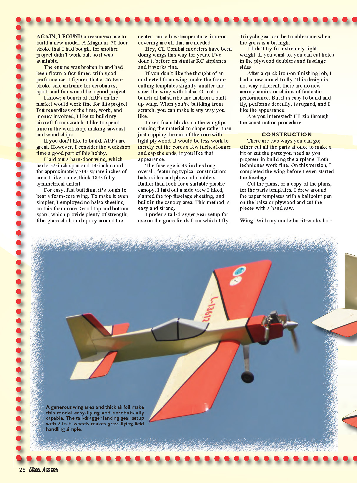
I laid out a barn-door wing with a 52-inch span and 14-inch chord, for approximately 700 square inches of area. I like a nice, thick, fully symmetrical 18% airfoil.
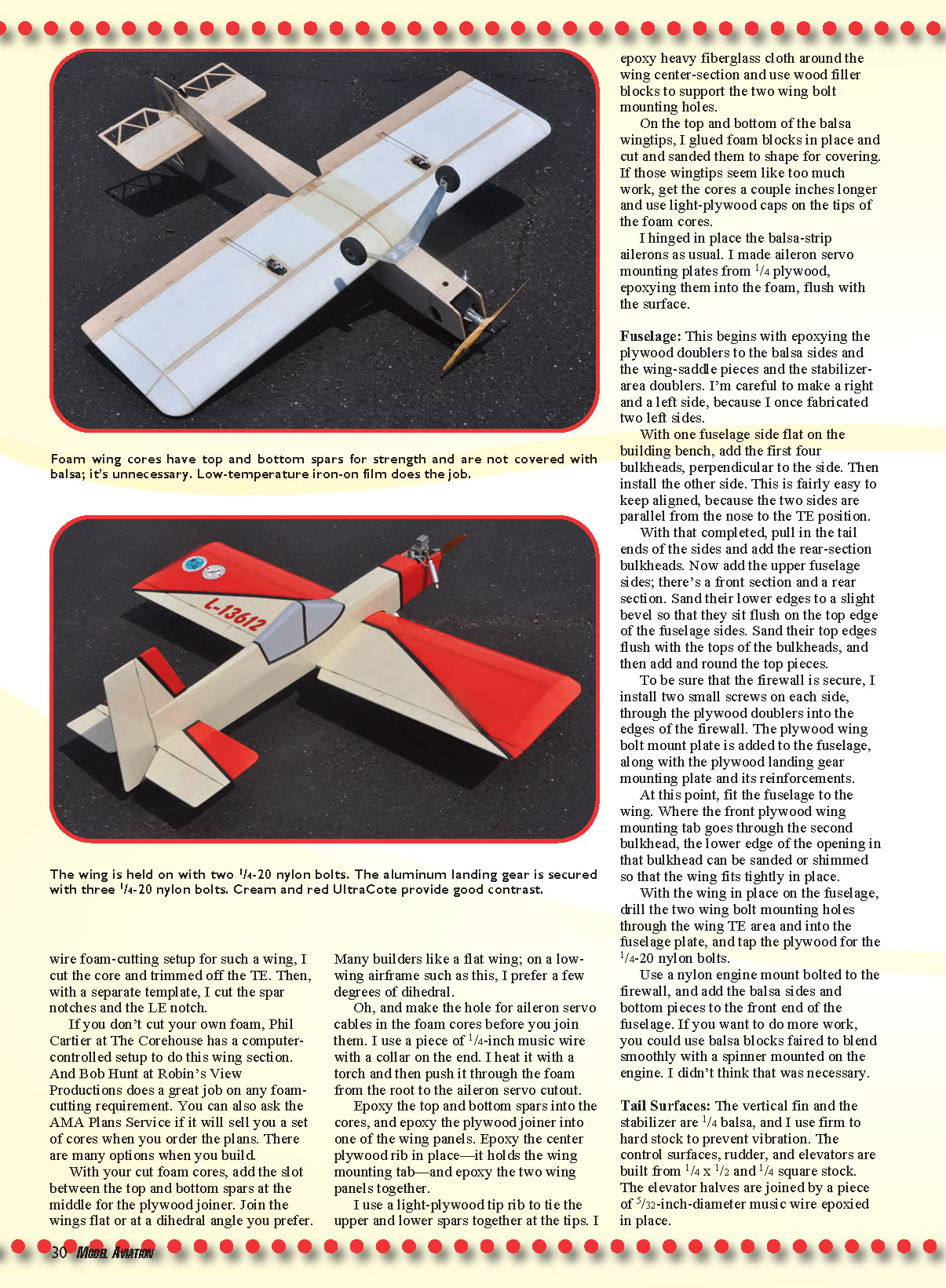
For easy, fast building it's tough to beat a foam-core wing. To make it even simpler, I employed no balsa sheeting on this foam core. Good top and bottom spars provide plenty of strength; fiberglass cloth and epoxy around the center; and a low-temperature, iron-on covering are all that are needed. CL combat modelers have been doing wings this way for years. I've done it before on similar RC airplanes and it works fine.
If you don't like the thought of an unsheeted foam wing, make the foam-cutting templates slightly smaller and sheet the wing with balsa. Or cut a bunch of balsa ribs and fashion a built-up wing. When you're building from scratch, you can make it any way you like.
I used foam blocks on the wingtips, sanding the material to shape rather than just capping the end of the core with light plywood. It would be less work to merely cut the cores a few inches longer and cap the ends, if you like that appearance.
The fuselage is 49 inches long overall, featuring typical construction: balsa sides and plywood doublers. Rather than look for a suitable plastic canopy, I laid out a side view I liked, slanted the top fuselage sheeting, and built in the canopy area. This method is easy and strong.
I prefer a tail-dragger gear setup for use on the grass fields from which I fly. Tricycle gear can be troublesome when the grass is a bit high.
I didn't try for extremely light weight. If you want to, you can cut holes in the plywood doublers and fuselage sides.
After a quick iron-on finishing job, I had a new model to fly. This design is not wildly different; there are no new aerodynamics or claims of fantastic performance. But it is easy to build and fly, performs decently, is rugged, and I like the appearance.
Are you interested? I'll zip through the construction procedure.
CONSTRUCTION
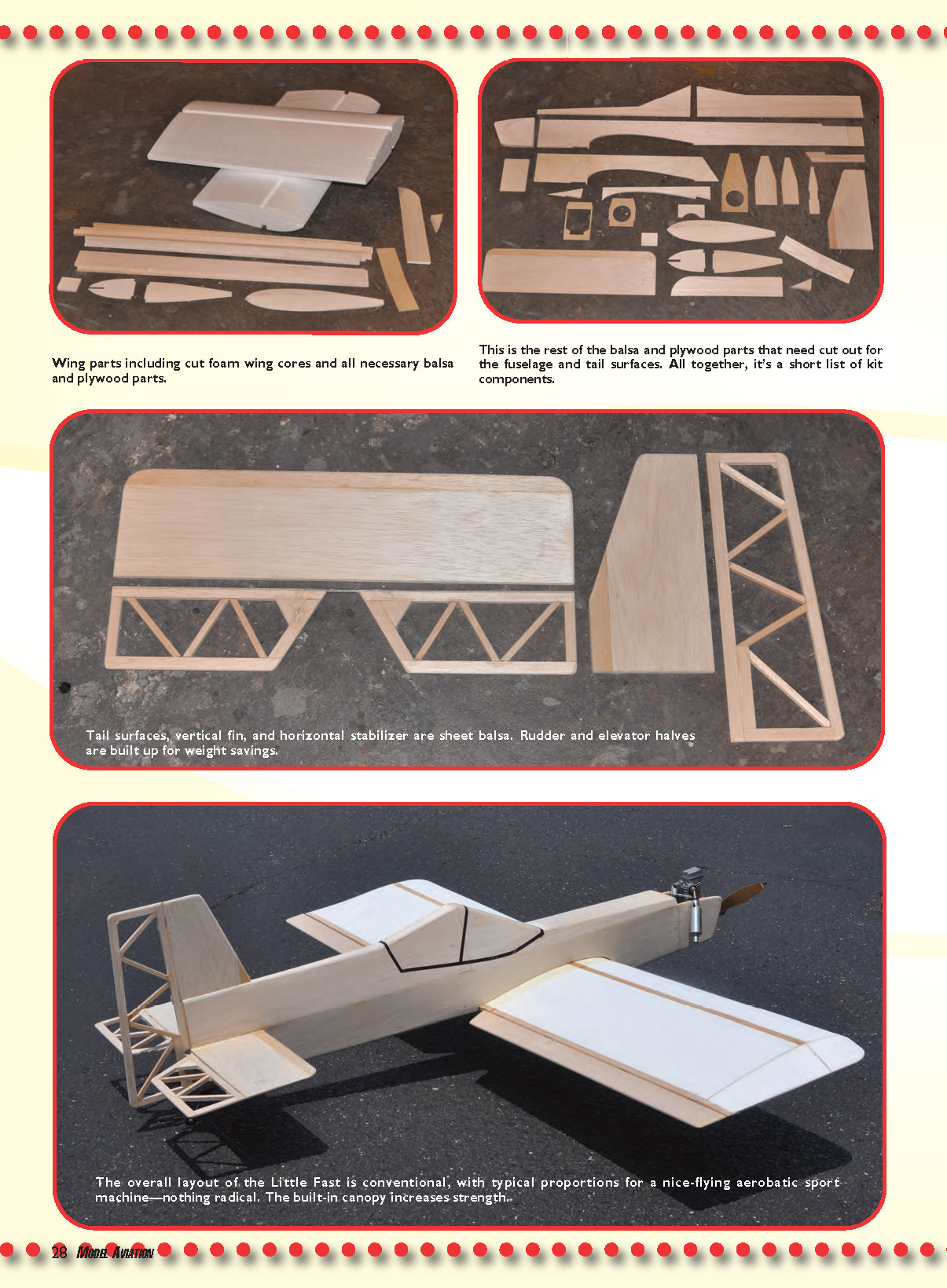
There are two ways you can go: either cut all the parts at once to make a kit or cut the parts you need as you progress in building the airplane. Both techniques work fine. On this version, I completed the wing before I even started the fuselage.
Cut the plans, or a copy of the plans, for the parts templates. I drew around the paper templates with a ballpoint pen on the balsa or plywood and cut the pieces with a bandsaw.
Wing
With my crude-but-it-works hot-wire foam-cutting setup for such a wing, I cut the core and trimmed off the trailing edge. Then, with a separate template, I cut the spar notches and the leading-edge notch.
If you don't cut your own foam, Phil Carter at The Corehouse has a computer-controlled setup to do this wing section. Bob Hunt at Robin's View Productions does a great job on any foam-cutting requirement. You can also ask the AMA Plans Service if it will sell you a set of cores when you order the plans. There are many options when you build.
With your cut foam cores, add the slot between the top and bottom spars at the middle for the plywood joiner. Join the wings flat or at a dihedral angle you prefer. Many builders like a flat wing; on a low-wing airframe such as this, I prefer a few degrees of dihedral.
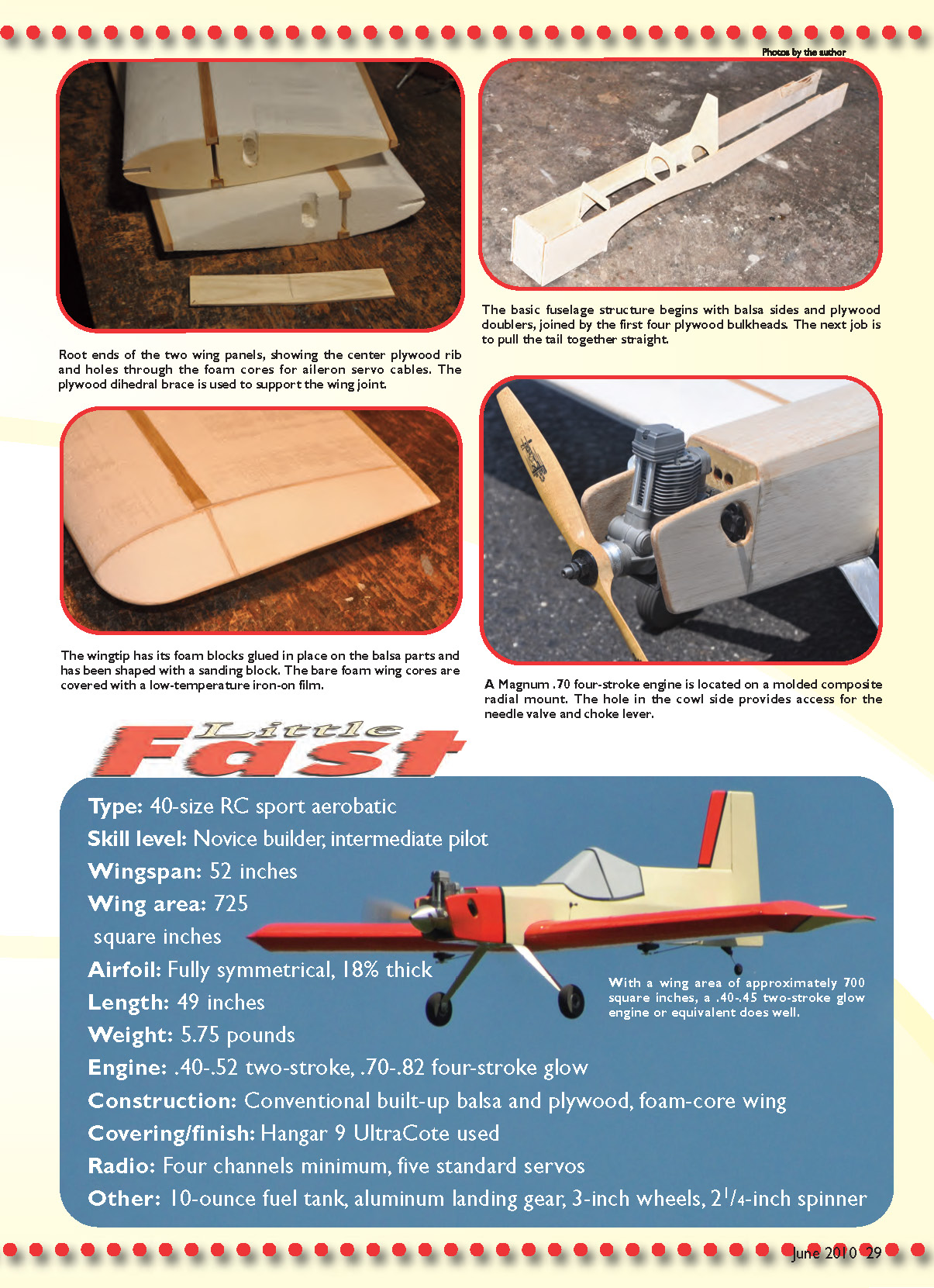
Make the hole for aileron servo cables in the foam cores before you join them. I use a piece of 1/4-inch music wire with a collar on the end. I heat it with a torch and then push it through the foam from the root to the aileron servo cutout.
Epoxy the top and bottom spars into the cores, and epoxy the plywood joiner into one of the wing panels. Epoxy the center plywood rib in place — it holds the wing mounting tab — and epoxy the two wing panels together.
Use a light-plywood tip rib to tie the upper and lower spars together at the tips. I epoxy heavy fiberglass cloth around the wing center-section and use wood filler blocks to support the two wing bolt mounting holes.
On the top and bottom of the balsa wingtips, I glued foam blocks in place and cut and sanded them to shape for covering. If those wingtips seem like too much work, get the cores a couple inches longer and use light-plywood caps on the tips of the foam cores.
I hinged in place the balsa-strip ailerons as usual. I made aileron servo mounting plates from 1/4-inch plywood, epoxying them into the foam, flush with the surface.
Fuselage
Begin by epoxying the plywood doublers to the balsa sides and the wing-saddle pieces and the stabilizer-area doublers. Be careful to make a right and a left side — I once fabricated two left sides.
With one fuselage side flat on the building bench, add the first four bulkheads perpendicular to the side. Then install the other side. This is fairly easy to keep aligned because the two sides are parallel from the nose to the trailing-edge position.
With that completed, pull in the tail ends of the sides and add the rear-section bulkheads. Now add the upper fuselage sides; there's a front section and a rear section. Sand their lower edges to a slight bevel so they sit flush on the top edge of the fuselage sides. Sand their top edges flush with the tops of the bulkheads, and then add and round the top pieces.
To be sure the firewall is secure, install two small screws on each side through the plywood doublers into the edges of the firewall. Add the plywood wing bolt mount plate to the fuselage, along with the plywood landing gear mounting plate and its reinforcements.
Fit the fuselage to the wing. Where the front plywood wing mounting tab goes through the second bulkhead, the lower edge of the opening in that bulkhead can be sanded or shimmed so that the wing fits tightly in place.
With the wing in place on the fuselage, drill the two wing bolt mounting holes through the wing trailing-edge area and into the fuselage plate, and tap the plywood for the 1/4-20 nylon bolts.
Use a nylon engine mount bolted to the firewall, and add the balsa sides and bottom pieces to the front end of the fuselage. If you want to do more work, you could use balsa blocks faired to blend smoothly with a spinner mounted on the engine. I didn't think that was necessary.
With the fuselage bolted onto the wing, insert the stabilizer and epoxy it in place, lining it up level with the wing. Insert the vertical fin and glue it in place, lining it up perpendicular with the stabilizer.
I like either fiberglass-tube pushrods or Sullivan's nylon-tube setup with carbon-fiber inner rods, and I use all 4-40 hardware. Cut holes in the rear bulkheads as required. When the rudder and elevator linkages are installed, you can install the bottom planking.
Tail Surfaces
The vertical fin and the stabilizer are 1/4-inch balsa; use firm to hard stock to prevent vibration. The control surfaces — rudder and elevators — are built from 1/4 x 1/2 and 1/4 square stock. The elevator halves are joined by a piece of 5/32-inch-diameter music wire epoxied in place.
Finishing
I used Hangar 9 UltraCote for the covering; it's one of the easier films to apply. With the equipment located as shown on the plans, the Little Fast balanced as shown and it works for me.
I've always thought that the balance point and control-surface movements should suit the pilot. There's a gigantic variation in the way individuals like their aircraft to "feel," but today's radios make it easy to set up a model to suit you.
I'm happy with the way the Magnum .70 four-stroke engine performs and am pleased with this latest building project. Hey — make some sawdust and wood chips!
Dick Sarpolus [email protected]
Specifications
- Type: 40-size RC sport aerobatic
- Skill level: Novice builder; intermediate pilot
- Wingspan: 52 inches
- Wing area: 725 square inches (approximately 700 sq in referenced earlier)
- Airfoil: Fully symmetrical, 18% thick
- Length: 49 inches
- Weight: 5.75 pounds
- Engine: .40–.52 two-stroke, .70–.82 four-stroke glow (Magnum .70 used here)
- Construction: Conventional built-up balsa and plywood, foam-core wing
- Covering/finish: Hangar 9 UltraCote used
- Radio: Four channels minimum, five standard servos
- Other: 10-ounce fuel tank, aluminum landing gear, 3-inch wheels, 2-1/4-inch spinner
With a wing area of approximately 700 square inches, a .40–.45 two-stroke glow engine or equivalent does well.
Sources
- Magnum Engines — (714) 963-0329 — http://magnum.globalhobby.com
- The Corehouse (Phil Carter) — (717) 566-3810 — http://home.earthlink.net/~philcartier/
- Robin's View Productions (Bob Hunt) — (610) 746-0106
- Sullivan Products — (410) 732-3500 — www.sullivanproducts.com
- Hangar 9 UltraCote — (800) 338-4639 — www.hangar-9.com
Transcribed from original scans by AI. Minor OCR errors may remain.

