
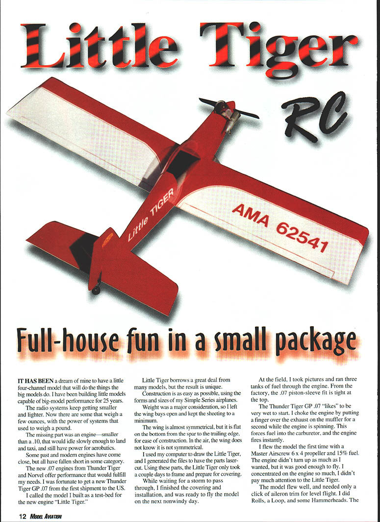
Little Tiger RC
It has been a dream of mine to have a little four-channel model that will do the things the big models do. I have been building little models capable of big-model performance for 25 years.
The radio systems keep getting smaller and lighter. Now there are transmitters that weigh a few ounces, with the power of systems that used to weigh a pound.
The missing part was an engine—smaller than a .10, that would idle slowly enough to land and taxi, and still have power for aerobatics.
Some past and modern engines have come close, but all have fallen short in some category. The new .07 engines from Thunder Tiger and Norvel offer performance that would fulfill my needs. I was fortunate to get a new Thunder Tiger GP .07 from the first shipment to the U.S.
I called the model I built as a test-bed for the new engine "Little Tiger."
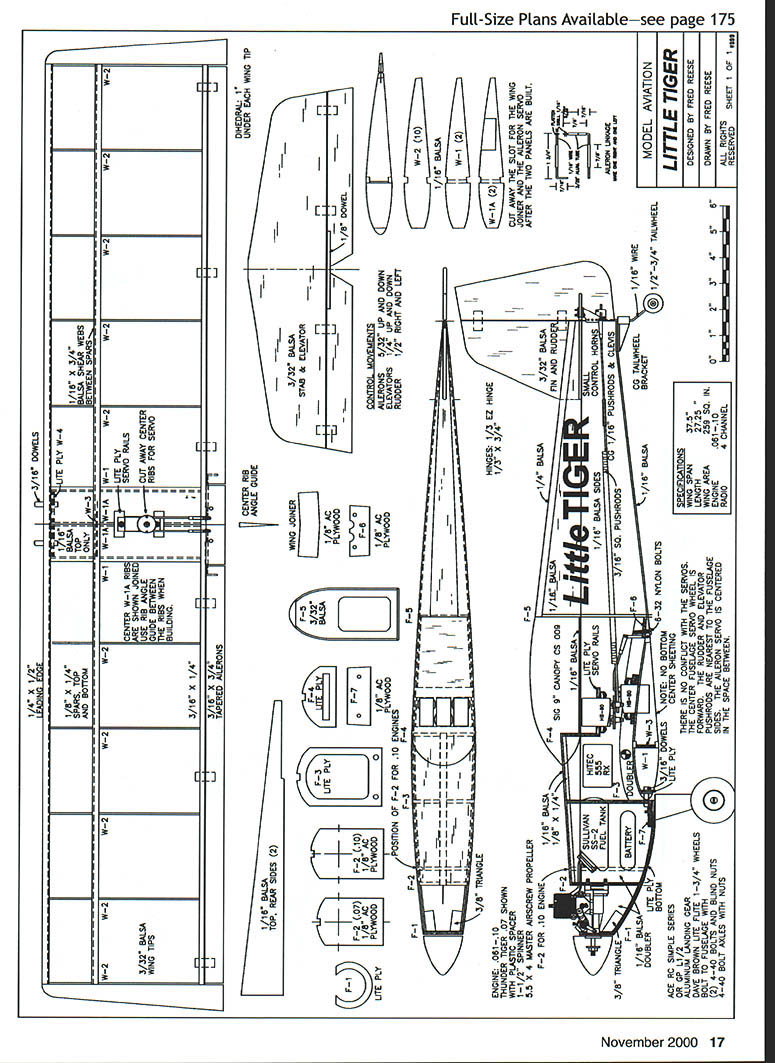
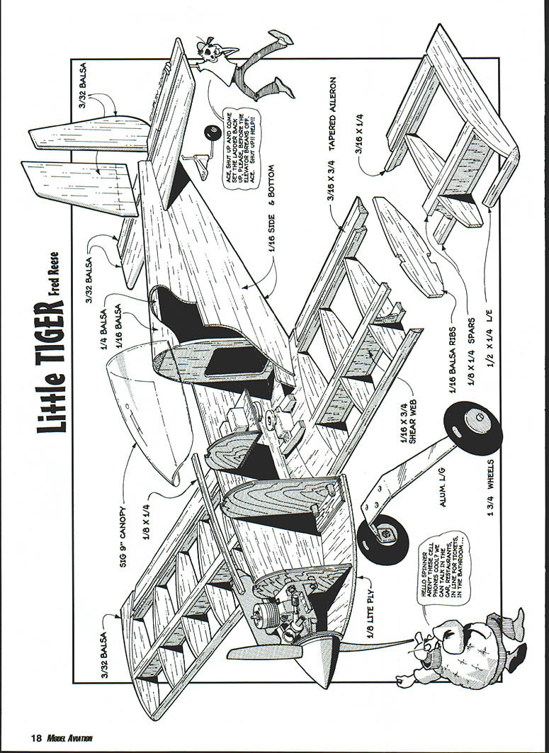
Little Tiger borrows a great deal from many models, but the result is unique. Construction is as easy as possible, using the forms and sizes of my Simple Series airplanes.
Weight was a major consideration, so I left the wing bays open and kept the sheeting to a minimum. The wing is almost symmetrical, but it is flat on the bottom from the spar to the trailing edge, for ease of construction. In the air, the wing does not know it is not symmetrical.
I used my computer to draw the Little Tiger, and I generated the files to have the parts laser-cut. Using these parts, the Little Tiger only took a couple days to frame and prepare for covering.
While waiting for a storm to pass through, I finished the covering and installation, and was ready to fly the model the next nonwindy day.
At the field, I took pictures and ran three tanks of fuel through the engine. From the factory, the .07 piston-sleeve fit is tight at the top. The Thunder Tiger GP .07 "likes" to be very wet to start. I choke the engine by putting a finger over the exhaust on the muffler for a second while the engine is spinning. This forces fuel into the carburetor, and the engine fires instantly.
I flew the model the first time with a Master Airscrew 6 x 4 propeller and 15% fuel. The engine didn't turn up as much as I wanted, but it was good enough to fly. I concentrated on the engine so much, I didn't pay much attention to the Little Tiger.
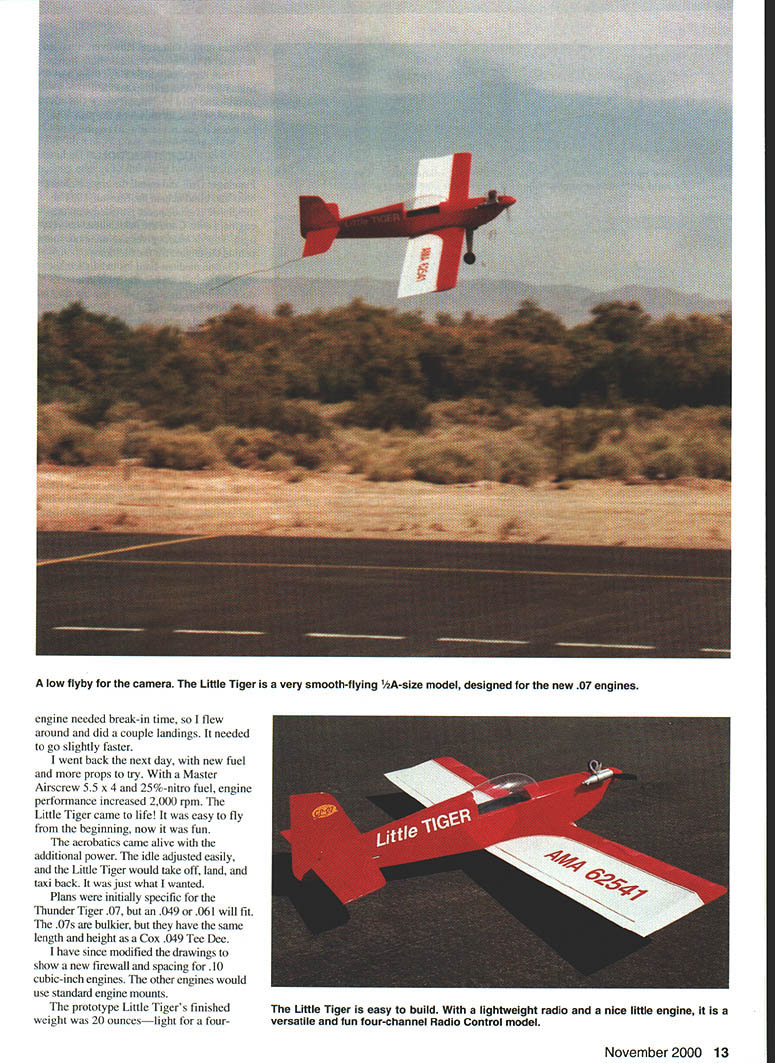
The model flew well, and needed only a click of aileron trim for level flight. I did rolls, a loop, and some hammerheads. The engine needed break-in time, so I flew around and did a couple landings. It needed to go slightly faster.
I went back the next day, with new fuel and more props to try. With a Master Airscrew 5.5 x 4 and 25% nitro fuel, engine performance increased about 2,000 rpm. The Little Tiger came alive. It was easy to fly from the beginning; now it was fun.
The aerobatics came alive with the additional power. The idle adjusted easily, and the Little Tiger would take off, land, and taxi back. It was just what I wanted.
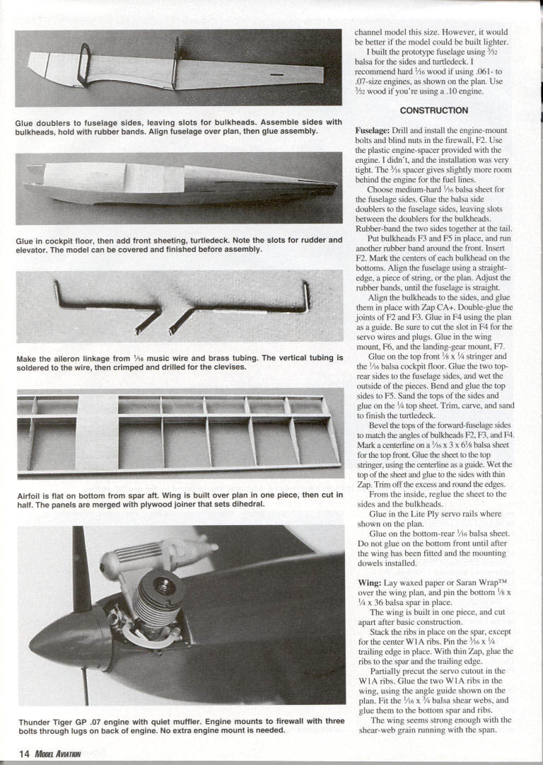
Plans were initially specific for the Thunder Tiger .07, but an .049 or .061 will fit. The .07s are bulkier, but they have the same length and height as a Cox .049 Tee Dee.
I have since modified the drawings to show a new firewall and spacing for .10 cubic-inch engines. The other engines would use standard engine mounts.
The prototype Little Tiger's finished weight was 20 ounces—light for a four-channel aerobatic model. With a lightweight radio and a nice little engine, it is a versatile and fun four-channel radio-control model. However, it would be better if the model could be built lighter.
I built the prototype fuselage using 3/32 balsa for the sides and turtledeck. I recommend hard 1/16 wood if using .061–.07-size engines, as shown on the plan. Use 3/32 wood if you're using a .10 engine.
Specifications
- Type: RC Sport
- Wingspan: 37½ inches
- Engine: .061–.10 cubic inch
- Functions: Ailerons, elevator, rudder, throttle
- Flying weight: 20 ounces
- Construction: Built-up balsa and plywood
- Covering/finish: Heat-shrink film
Construction
Fuselage
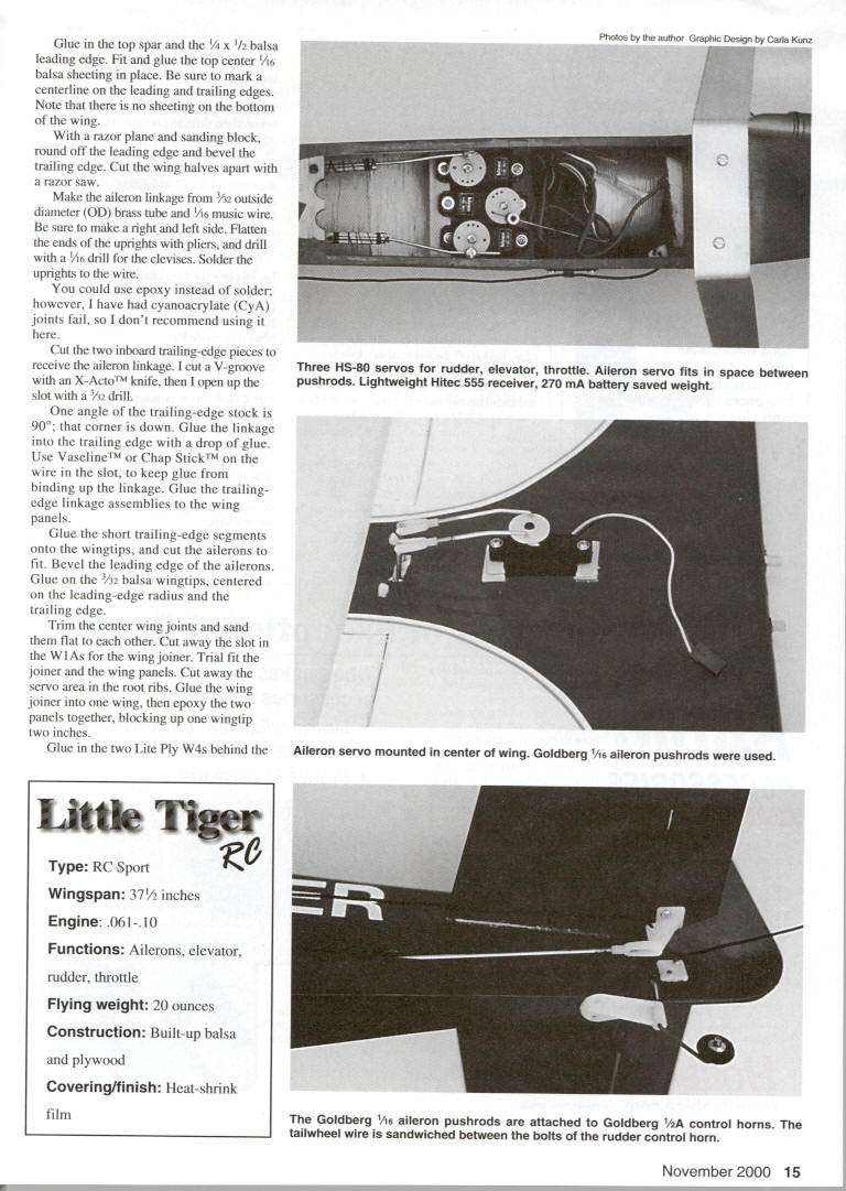
- Drill and install the engine-mount bolts and blind nuts in the firewall (F2). Use the plastic engine-spacer provided with the engine. The 3/16 spacer gives slightly more room behind the engine for the fuel lines.
- Choose medium-hard 1/8 balsa sheet for the fuselage sides. Glue the balsa side doublers to the fuselage sides, leaving slots between the doublers for the bulkheads.
- Rubber-band the two sides together at the tail. Put bulkheads F3 and F5 in place, and run another rubber band around the front. Insert F2.
- Mark the centers of each bulkhead on the bottoms. Align the fuselage using a straightedge, a piece of string, or the plan. Adjust the rubber bands until the fuselage is straight.
- Align the bulkheads to the sides and glue them in place with Zap CA+. Double-glue the joints of F2 and F3.
- Glue in F4 using the plan as a guide. Be sure to cut the slot in F4 for the servo wires and plugs.
- Glue in the wing mount (F6) and the landing-gear mount (F7).
- Glue on the top front 1/8 x 1/4 stringer and the 1/16 balsa cockpit floor.
- Glue the two top rear sides to the fuselage sides, wet the outside of the pieces, bend and glue the top sides to F5. Sand the tops of the sides and glue on the 1/8 top sheet. Trim, carve, and sand to finish the turtledeck.
- Bevel the tops of the forward-fuselage sides to match the angles of bulkheads F2, F3, and F4. Mark a centerline on a 1/16 x 3 x 6 balsa sheet for the top front. Glue the sheet to the top stringer, using the centerline as a guide. Wet the top of the sheet and glue to the sides with thin Zap. Trim off the excess and round the edges. From the inside, reglue the sheet to the sides and the bulkheads.
- Glue in the Lite Ply servo rails where shown on the plan.
- Glue on the bottom-rear 1/16 balsa sheet. Do not glue on the bottom front until after the wing has been fitted and the mounting dowels installed.
Wing
- Lay waxed paper or Saran Wrap™ over the wing plan, and pin the bottom 1/8 x 1/4 x 36 balsa spar in place.
- The wing is built in one piece and cut apart after basic construction. Stack the ribs in place on the spar, except for the center W1A ribs. Pin the 3/16 x 1/4 trailing edge in place.
- With thin Zap, glue the ribs to the spar and the trailing edge.
- Partially precut the servo cutout in the W1A ribs. Glue the two W1A ribs in the wing, using the angle guide shown on the plan.
- Fit the 1/8 x 3/4 balsa shear webs and glue them to the bottom spar and ribs. The wing seems strong enough with the shear-web grain running with the span.
- Glue in the top spar and the 1/4 x 1/2 balsa leading edge. Fit and glue the top center 1/16 balsa sheeting in place. Be sure to mark a centerline on the leading and trailing edges. Note that there is no sheeting on the bottom of the wing.
- With a razor plane and sanding block, round off the leading edge and bevel the trailing edge. Cut the wing halves apart with a razor saw.
- Make the aileron linkage from 3/32" outside-diameter brass tube and 1/16" music wire. Make a right and left side. Flatten the ends of the uprights with pliers, and drill with a 1/16" drill for the clevises. Solder the uprights to the wire. (Epoxy can be used instead of solder, but CyA joints have been known to fail.)
- Cut the two inboard trailing-edge pieces to receive the aileron linkage. Cut a V-groove with an X-ACTO knife, then open up the slot with a 3/32" drill.
- One angle of the trailing-edge stock is 90°; that corner is down. Glue the linkage into the trailing edge with a drop of glue. Use Vaseline™ or Chap Stick™ on the wire in the slot to keep glue from binding up the linkage. Glue the trailing-edge linkage assemblies to the wing panels.
- Glue the short trailing-edge segments onto the wingtips and cut the ailerons to fit. Bevel the leading edge of the ailerons. Glue on the 3/32" balsa wingtips, centered on the leading-edge radius and the trailing edge.
- Trim the center wing joints and sand them flat to each other. Cut away the slot in the W1As for the wing joiner. Trial fit the joiner and the wing panels. Cut away the servo area in the root ribs.
- Glue the wing joiner into one wing, then epoxy the two panels together, blocking up one wingtip two inches.
- Glue in the two Lite Ply W4s behind the leading edge, between the W1 and W1A ribs on each side.
Empennage
- Cut out the tail parts and sand the edges.
- Join the elevator halves with a 1/8" dowel.
Assembly
- Fit the wing into the wing saddle. Run a piece of sandpaper between the saddle and the wing, sanding the saddle for a finished fit.
- Center the wing in the fuselage, and drill a 3/16" hole through one hole in F3 and through the leading edge of the wing. Push a piece of 3/16" dowel through the leading edge and F3. Glue the dowel into the wing with a drop of thin Zap. Drill the other side, and install the second dowel.
- Remove the wing, and glue both dowels with thin Zap from the front of the leading edge. Round off the fronts of the dowels.
- Put the wing in the fuselage, and install the two wing bolts at the trailing edge. Drill and tap and install the two mounting bolts, one at a time. Use 6-32 or 8-32 nylon bolts—whichever you can get. Harden the holes in the wing and the threads in F7 with thin Zap. Retap the threads.
- With the wing installation complete, finish the front of the fuselage: cut a piece of Lite Ply for the bottom, with the outer grain perpendicular to the fuselage so it will bend easily. Wet the outside surface of the Lite Ply bottom, and spritz the inside surface with ZIP Kicker. Apply medium Zap to the landing-gear mount, F7, and the fuselage sides. Put the Lite Ply bottom in place against the landing-gear mount, and hold for a few seconds as the glue sets. Bend the bottom to the sides and hold until set.
- Glue one-inch lengths of triangle stock between the sides and bottom at the front. Sand the front even with the sides.
- Bolt the engine in place, and install a 1-1/4" spinner. Check the fit and spacing of F1 to the spinner. Glue F1 to the front, and mark the spinner position on F1. Remove the engine, and carve and sand the front of the fuselage to the mark on F1. Glue in bits of triangle between the sides and F1 at the top, to fill the small gap.
- Drill two 1/8" holes in the aluminum landing gear for the mounting bolts. Use these holes as a guide to drill the holes in the fuselage bottom. Drill out the two holes in the fuselage with a 5/32" drill. Install two 4-40 blind nuts inside F7.
Covering and Finish
- Cover the model with your favorite covering film. Goldberg UltraCoat® was used on the prototype.
- Seal the engine compartment with Z-poxy finishing resin, and seal the fuel tank area with polyurethane spray.
- Trim away the covering over the stabilizer slot, and cut the slot in the top of the fuselage for the fin. Cover the parts and cut away the covering for the glue joints before gluing into the fuselage.
- Install the hinges (Sig Easy Hinges cut into thirds were used). Glue the stabilizer into the fuselage. Do not glue in the fin until after final sanding and finishing.
- Apply the trim and other decorations. Use a standard Sig 9- or 10-inch bubble canopy (CS 009 or 010). Cut the canopy to fit the fuselage, and glue it in place with Formula 56 canopy glue. Formula 56 will bond the plastic canopy to the covering film. Hold the canopy in place with rubber bands or tape overnight until the glue dries.
Equipment Installation
- In the prototype I used Hitec HS-80 servos, a Hitec 555 microreceiver, and a 270 mAh battery pack. With this lightweight radio pack, the model balanced as shown on the plan.
- Install the three fuselage servos. The center output is forward. Install EZ connectors to the servo output wheels. The rudder and elevator pushrods are as close to the fuselage sides as possible.
- Drill a 1/16" hole for the 1/32" throttle pushrod through F2, touching the fuselage side and even with the bottom of the engine-beam mount lugs.
- Make a small Z-bend in the end of the 1/32" music-wire pushrod for the carburetor arm, which has been rotated to the down position. The wire will also pass through the side of F3 before arcing over to the center servo output. Install an Allen-head set screw from a wheel collar into the throttle EZ connector so it will tighten on the 1/32" wire.
- Assemble and fit the fuel tank. A two-ounce tank is ample for the Thunder Tiger .07. Use the silicone tube provided with the engine for the clunk line inside the tank; it is much more flexible than the tubing provided with the tank.
- Drill the fuel-line holes through F2, and slide the tank into place. Bring the brass tubes through the firewall and fit the tank snugly between the fuselage sides at the firewall. Relieve the tank for the throttle pushrod.
- Heat up your covering iron to 300°F and gently dent the side of the tank at the front to clear the pushrod. The iron must be hot enough to soften the plastic, but not melt it.
- Slide the fuel tank in place, and mount the engine. Check the pushrod to make sure it works easily. When satisfied with the fit, make the bends in the ends of the tubes to line up with the engine and muffler nipples. When installing the engine-mount bolts for the last time, use Loctite® so they do not vibrate loose.
- Bend the tailwheel wire into the Goldberg tailwheel bracket, and glue the assembly in place. Slide the fin and rudder in place, and mark the rudder for the tailwheel wire. Drill with a 1/16" drill. Slide the rudder and fin in place, line it up, and glue in place. Bolt the rudder control horn in place over the wire when installing the pushrod.
- Mount the landing gear to the fuselage. Attach Dave Brown Lite Flite wheels with 4-40 x 1" bolts and nuts. The landing gear angles back.
- Make the two pushrods, using the plans side-view as a guide. Bend the ends of the pushrod wires 90° and cut off close, to leave a small tang to dig into the balsa pushrods. The tang will keep the pushrods from slipping. Bind the wires to the balsa pushrods with thread and thin Zap.
- To make adjusting the nylon clevises easier, run a 2-56 tap into each clevis.
- Install the rudder clevis and attach it to the rudder control horn, one hole in from the tip. Attach the elevator pushrod clevis to the elevator control horn. Position the horn on the elevator, drill the two bolt holes, and install.
- Mount the radio switch on the side opposite the exhaust. Wrap the receiver and battery pack with 1/4" lightweight foam rubber and tape. Hook up all the wires, and put the receiver and pack in place. Turn on the radio, and adjust the pushrods, control direction, and control-surface movement. Tighten all EZ connectors and snap the clevises.
- Cut the hole in the wing for the aileron servo and cut away the ribs. Cut away the covering for the aileron servo rails, and glue the rails in place. Note that the rear mount is doubled. Screw the servo in place.
- Cut and bend the Goldberg 1/16" aileron pushrods (No. 351) to fit, using Z-bends into the servo output. Note that the end bend is down through the output. Adjust the ailerons for 5/32" travel up and down.
Balance and Final Setup
- Balance the model at 28% to 30% of the mean aerodynamic chord. A test glide should be made first with the engine off to check center of gravity and trim. The prototype required a small amount of down elevator and right rudder.
- Adjust the balance of the model. The Little Tiger should balance 1/4" ahead of the spar (approximately 25% of the chord).
Flying
- Spend some time breaking in the engine before flying. The Thunder Tiger .07 was tight at top dead center out of the box. The author flew the model after three tanks of fuel had been run through the engine and recommends no less.
- Initial fuel was 15% with castor and synthetic oil, changed to 25% after 10 runs.
- Several propellers were tried, settling on a Master Airscrew 5.5 x 4. It turns 17,000 rpm with the 25% fuel and flies the Little Tiger very nicely.
- Neither a 7 x 3 nor a 6 x 4 propeller achieved enough rpm to really get the airplane up on step. The Thunder Tiger .07 turns a 7 x 3 Master Airscrew propeller 12,000–13,000 rpm; with a 5.5 x 4 it will fly low and slow—especially with the very low idle and good transition to the top end of the engine.
- Adjust the needle-valve screw if the engine speeds or slows down at the low-idle setting. The aircraft should be able to sit with no rolling at idle.
- The stock muffler is very effective. It quiets the engine and reduces the irritating pitch associated with most other small engines.
- The takeoff is straight and easily steered with the rudder. The Little Tiger runs on the mains for approximately 30 feet, then lifts off and flies away. Maintain a gentle climbout until it reaches a comfortable altitude.
- The ailerons are effective, the elevator is not sensitive, and the rudder is powerful. The model does all the aerobatics, but what it does best is throttle back and land with the engine running.
- For launches, a hand toss with half throttle is satisfactory. Fly the Little Tiger slowly at first, and gradually increase speed and maneuvering as confidence is gained.
Notes
- The wing loading is 11.5 oz./sq. ft.
- Laser-cut parts were created for the magazine plans and will be offered for a limited time.
Fred Reese 2500 Teddy Dr. #2 Las Vegas, NV 89102 [email protected]
Transcribed from original scans by AI. Minor OCR errors may remain.

