
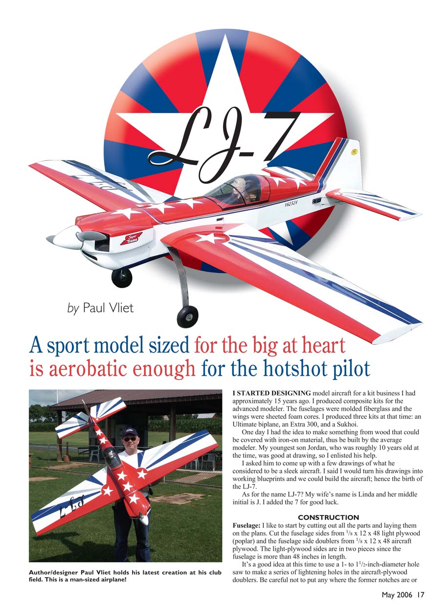
LJ-7
by Paul Vliet
A sport model sized for the big at heart is aerobatic enough for the hotshot pilot.
I started designing model aircraft for a kit business I had approximately 15 years ago. I produced composite kits for the advanced modeler. The fuselages were molded fiberglass and the wings were sheeted foam cores. I produced three kits at that time: an Ultimate biplane, an Extra 300, and a Sukhoi.
One day I had the idea to make something from wood that could be covered with iron-on material, thus be built by the average modeler. My youngest son Jordan, who was roughly 10 years old at the time, was good at drawing, so I enlisted his help.
I asked him to come up with a few drawings of what he considered to be a sleek aircraft. I said I would turn his drawings into working blueprints and we could build the aircraft; hence the birth of the LJ-7.
As for the name LJ-7? My wife's name is Linda and her middle initial is J. I added the 7 for good luck.
CONSTRUCTION
Fuselage
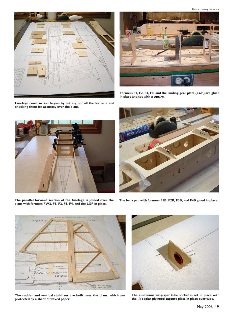
- Cut out all parts and lay them on the plans.
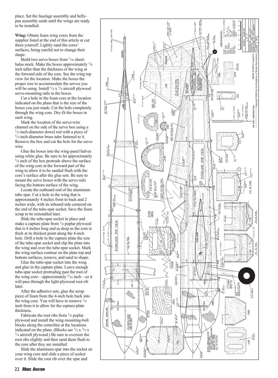
- Cut the fuselage sides from 1/8 x 12 x 48 light plywood (poplar). Cut the fuselage side doublers from 1/8 x 12 x 48 aircraft plywood. The light-plywood sides are in two pieces since the fuselage is more than 48 inches long.
- Optionally use a 1- to 1-1/2-inch-diameter hole saw to make a series of lightening holes in the aircraft-plywood doublers. Avoid former notches and wing-bolt locations.
- Cut all formers, the firewall, and other parts, starting with the largest pieces and progressing to small parts. Some small parts can be made from scrap.
- Glue the fuselage doublers to the fuselage sides with slow-curing epoxy. Adhere the front and rear portions of the fuselage sides to the doublers at the same time, making sure to produce a left and a right side.
- Epoxy the 1/8 aircraft-plywood doublers (FSDT) in place at the tail.
- Use a straight and true building board—author uses an old Formica-covered countertop secured and shimmed into alignment before each use.
- Install the landing-gear plate (LGP) between formers F1 and F2 and set them in place over the side view of the plans. Ensure F1 and F2 slots have enough slop to allow the plate to sit at the proper angle.
- Lay one fuselage side flat on the building board and glue in formers FW2, F1, F2 (with the LGP installed between them), F3, and F4, set with a square. Tape the fuselage plan top view to the building board and cover it with waxed paper.
- Set the assembled fuselage side (with glued formers) over the other fuselage side and glue the two together. Add top and bottom sheeting and stringers, then sand and fair the fuselage to shape.
- Set the fuselage assembly and belly-pan assembly aside until the wings are ready to be installed.
Additional fuselage steps:
- Install the opposite fuselage side by snapping it over the formers and fixture it with plywood. Glue the second side to the formers using thick cyanoacrylate; hold the bottom together with bar clamps until the glue sets.
- Install a 1/4 x 3/8 aircraft-plywood beam to the underside of the LGP, running fore and aft into the notches in formers F1 and F2; epoxy in place.
- Pull one fuselage side behind former F4 at a time onto the plan lines and fixture with 1/2 plywood. Use a scrap piece of 1/4 aircraft plywood to make a 90° fixture set between the sides where the vertical stabilizer post will be, to maintain the 1/4-inch space between fuselage sides at the rear. Glue formers F5 and F6 in place. Remove clamps after glue sets.
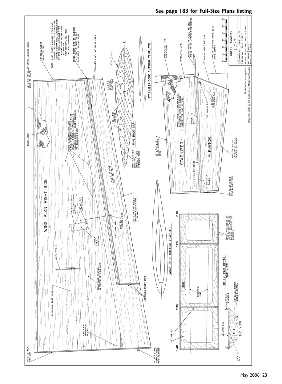
- Cover bottom of formers F2–F4 and the exposed fuselage sides between them with waxed paper and set the belly-pan base (BPB) in place. Bevel the sides of the BPB to accommodate belly-pan sheeting.
- Tape the BPB in place. Make belly-pan rail material from 1/8 x 3/8 aircraft plywood and install the belly-pan rails with thick cyanoacrylate on the inside of the fuselage against the underside of the BPB and the inside edge of the fuselage sides. The rails run in three sections between F1–F2, F2–F3, and F3–F4. Use the BPB openings to hold rails in place until glue sets; waxed paper prevents rails from gluing to fuselage sides.
- Glue formers F1B, F2B, F3B, and F4B in place.
Wing
- Obtain foam wing cores from a supplier or cut them yourself. Lightly sand the cores' surfaces without changing their shape.
- Build two servo boxes from 1/16 x 4 x 48 balsa stock. Make the boxes approximately 1/8 inch taller than the thickness of the wing at the forward side of the core. Size the boxes for the servos you will use. Install 1/4 x 3/8 aircraft-plywood servo-mounting rails in the boxes.
- Cut a hole in the foam core at the location indicated on the plans to the size of the servo boxes. Cut completely through the core and dry-fit the boxes.
- Mark the servo-wire channel on the side of the servo box using a 1/2-inch-diameter dowel with a piece of 1/2-inch-diameter brass tube fastened to it. Remove the box and cut the hole for the servo wire.
- Glue the boxes into the wing-panel halves using white glue. Let approximately 1/8 inch of the box protrude above the wing surface at the forward part so it can be sanded flush later. Mount servo boxes with servo rails facing the bottom surface of the wing.
- Locate the outboard end of the aluminum-tube spar. Cut a hole in the wing approximately 4 inches front-to-back and 2 inches wide, with its inboard side centered on the end of the tube-spar socket. Save the foam scrap for later reinstallation.
- Slide the tube-spar socket in place and make a capture plate from 1/8-inch poplar plywood, 4 inches long and as deep as the core thickness at the thickest point along the 4-inch hole. Drill a hole in the capture plate the size of the tube-spar socket and slip the plate into the wing over the socket. Mark the wing-surface contour on the plate top and bottom, remove, and sand to shape.
- Glue the tube-spar socket into the wing and glue in the capture plate. Leave about 3/16 inch of socket protruding past the root so it will pass through the light-plywood root rib later. After adhesive sets, glue the foam scrap back into the hole, removing 1/8 inch to allow for capture-plate thickness.
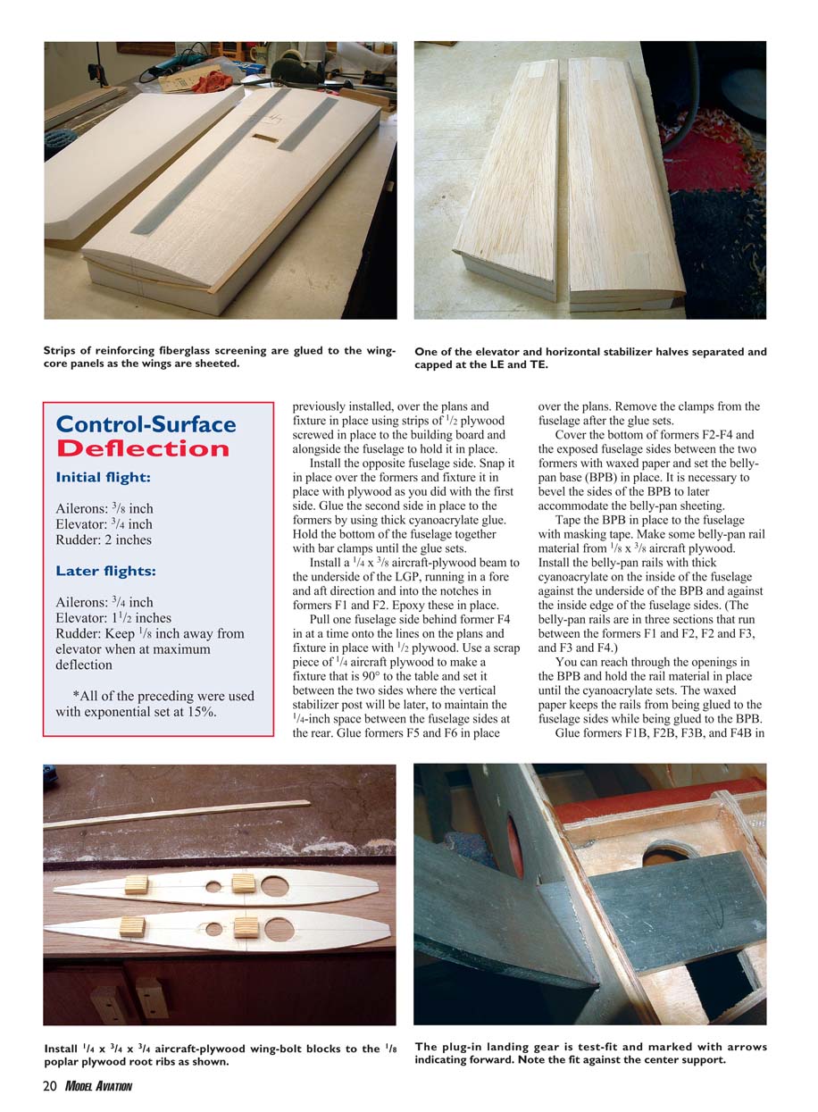
- Fabricate root ribs from 1/8-inch poplar plywood and install wing-mounting bolt blocks along the centerline at plan locations. (Blocks: 3/4 x 3/4 x 1/4-inch aircraft plywood.) Oversize root ribs slightly and sand flush after installation.
- Slide the aluminum spar into the wing socket, slide a piece of socket over it, then slide the root rib over the spar up against the core with the wing-bolt blocks touching the wing core. Line up the root rib outside with the wing-core surface and press down firmly to indent the foam core with the wing-bolt blocks. Remove the root rib and remove foam in the impressions to a depth of 1/4 inch (a Dremel with router base is useful). Glue the root rib in place with epoxy or white glue and tape until dry. Sand flush with a block. Repeat for the other wing.
- Prepare wing sheeting from 1/16 x 4 x 48 balsa. Edge-glue three sheets together with the grain running parallel.
- For reinforcement, buy fiberglass screening (window-screen type) or cut similar material. Cut into 1-1/2-inch strips. Place one strip directly over the wing spar from about 1 inch in from the root to approximately 2 inches from the tip. Place another roughly 16-inch strip 1 inch from the root ending near the servo pocket; its aft edge should be about 1 inch aft of the servo-box rear. Do this on both top and bottom of each wing and glue strips with laminating resin just prior to gluing wing skins.
- Apply laminating resin to one bottom skin (do not apply to foam core). Place glued-up bottom skin in its bottom cradle and set the core on top. Glue the top skin and set it on the core. Put the top cradle in place and weight the assembly with heavy objects (concrete blocks recommended). This must be done on your straight and true building board.
- Measure from the wing leading-edge (LE) and trailing-edge (TE) centerline to the surface of the building board. Measurements should be consistent; shim to correct if needed. Repeat for the other wing panel and for the horizontal stabilizer/elevator piece.
- After resin cures, cap the LE with 1/2-inch balsa and carve/sand to shape. Cap wingtips with 1/4-inch balsa and sand. Repeat for the horizontal stabilizer/elevator.
- Mark the aileron hinge line on both wing panels. Draw additional lines 1/4 inch on either side of the hinge line as cut lines. Mark lines on both sides and cut halfway through from each side, then slice between the cut line and hinge line and sand down to the cut line after removing the aileron.
- Cap aileron LE and wing TE with 1/4-inch balsa. Put a hinge line at the center of the aileron LE and block-sand the LE to a bevel from the rear side of the 1/4-inch cap to the hinge line (top and bottom).
- Install a 7/16-inch-diameter dowel into the aileron for control-horn installation (see wing top view for location).
Mounting the wings:
- Mark a pencil line on both fuselage sides 2-1/2 inches down from the thrustline (if the fuselage is upside-down, the line is 2-1/2 inches up from the table). Return the fuselage upside-down to the building board and weight it to prevent movement.
- Slide the aluminum tube spar into the fuselage and install your wing-mounting kit in both sides.
- Place a piece of 1/2-inch plywood on the table about the length of the spar and the width of the wing panel as a shim while setting the wing panel.
- Place the wing panel in the top foam cradle and tape the cradle to the wing panel, ensuring the cradle LE is 1/2 inch back from the capped LE so it remains in its original position relative to the foam core.
- Slide the wing panel onto the spar and push it up close to the fuselage. Check that the centerlines on the LE and TE match the line drawn on the fuselage side. Adjust with wing-mounting kit adjusters if needed.
- When aligned, slide the wing away about 1 inch and place a 1/4-inch-diameter dowel center in each fuselage wing-bolt hole. Press the wing panel against the dowel centers to mark wing-bolt hole locations in the panel. Drill and tap the wing-bolt holes in the wing for 1/4-20 nylon bolts. Repeat for the other wing panel.
Stabilizer and Elevator
- Mark the hinge line on each stabilizer half per the plans. Mark an additional 1/4 inch on either side of the hinge line as the cut lines to separate elevator from stabilizer.
- Cut the elevators from the stabilizers. Place stabilizer halves in their bottom cradles with about 1/2 inch of the root hanging over the cradle. Glue stabilizer halves together with slow-setting epoxy and tape across the joint until epoxy sets.
- Cap elevator LEs with 1/4-inch balsa, mark a center hinge line, and taper the edge to a bevel from the elevator surface to the hinge line. Cap the TE of the stabilizer with 1/4-inch balsa as a continuous piece from one side to the other.
Completing the Fuselage
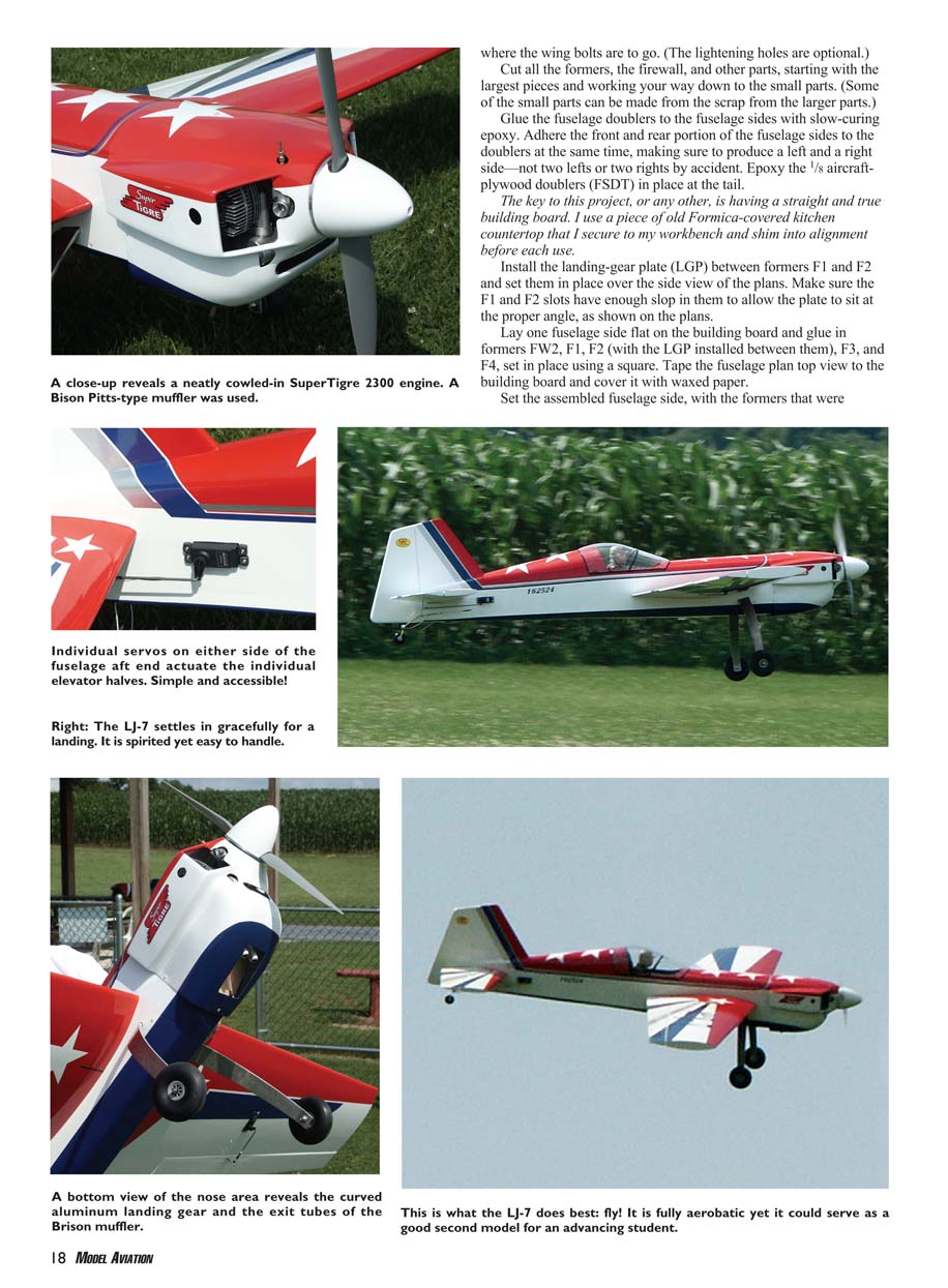
- Install the landing gear. The gear is split in half at the center; each half slips through its respective side slot in the fuselage.
- After inserting the gear, remove additional aluminum so the end of the gear rests against the center support beam on the bottom of the LGP and the forward part of the angled mark on the gear underside just touches the outside of the fuselage.
- Drill the gear for two 8-32 socket-head bolts each. Mark bolt holes in each landing-gear half and install blind nuts in the LGP from the top side.
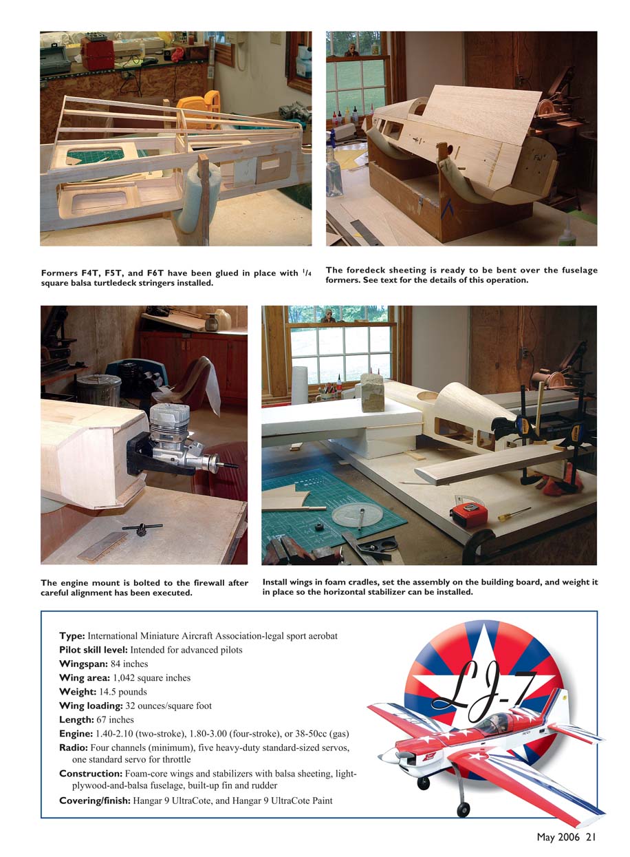
- Glue all top formers into position and install 1/4-inch square spars. Install the cockpit floor from 1/8 balsa with grain running side-to-side. Cover turtledeck and foredeck with 3/32 balsa sheet and sand to final shape.
- Suggested technique: soak turtledeck and foredeck balsa sheeting in a solution of ammonia and hot water before bending to make the wood more pliable.
- Install 1/8 balsa sheeting to the bottom aft fuselage and sand to final shape. Install Firewall Bottom (FWB); bevel this former where it meets the firewall. Install 1/8-inch sheeting between FWB and F1 and sand to final shape. Sheet the belly pan with 1/8 balsa and sand to final shape.
- Glue in the 1/4-inch aircraft-plywood tail-wheel block with epoxy and sand to shape.
Mounting the Horizontal Stabilizer
- With landing gear removed, install and bolt the wings in place. Tape the bottom wing cradle to each wing. Shim the entire cradle up off the table at least 2 inches on both sides and weight it down so it can’t move. Wings should now be at 0° incidence.
- Draw a centerline on the stabilizer TE. Set the stabilizer in its saddle. At the firewall, stick a pin in the center of the top 1/4-inch square stringer as your measuring reference point.
- With stabilizer set to 0° incidence, measure down to the table from the TE centerline on both sides—the measurements should match. Measure from the firewall pin to the rear outboard corner of the stabilizer on both sides—the measurements should match. Trim the saddle if necessary to achieve proper dimensions.
- When measurements and incidence are correct, epoxy the horizontal stabilizer in the saddle.
Tail Blocks
- Make a sanding fixture from 1/4-inch balsa stock shaped like the balsa tail blocks front-to-back and sheet it on both sides with 1/16-inch balsa except where it goes into the vertical stabilizer post slot.
- Tack-glue this sheet in place and tack-glue the rough-cut tail blocks to it. Shape the tail blocks without the vertical stabilizer in the way. After shaping, remove the blocks and set them aside.
Installing the Vertical Stabilizer
- Dry-fit the vertical stabilizer by slipping its post into the slot between the fuselage sides. It should sit down to the 1/4-inch plywood tail-wheel plate and be in full contact with the horizontal stabilizer and former F6.
- Epoxy the vertical stabilizer in place to the fuselage sides, horizontal stabilizer, and former F6. Remove excess glue. Use a square on the table to ensure the vertical stabilizer is perpendicular to the table and the horizontal stabilizer. Epoxy the tail blocks in place.
Final Assembly
- Install hinges on all control surfaces.
- Author’s preferred control-horn method: install 4-40 fully threaded rods into the dowels previously installed in the control surfaces, leaving about 1 inch sticking above the surface; thread in enough rod to almost cover dowel length. Attach a Du-Bro E/Z Attach Horn Bracket for the clevis.
- Mount the engine with 1-1/2° right thrust and set the cowling. Author mounted cowling with 4-40 nylon screws.
- Mount the belly pan with a 1/4-inch dowel through rear F4 former glued to F4B, then run two 4-40 nylon bolts through the fuselage into the aircraft-plywood rails of the belly pan just forward of the landing gear.
- Author used a Goldberg steerable tailwheel assembly and Du-Bro light foam tires.
Engine
- Author’s power: Super Tigre 2300 with a Bison Pitts-type muffler; it fits well into the cowling. Exhaust tubes from the Bison muffler were the correct length and needed no extension.
- The aircraft was designed around the older Super Tigre 3000 with a cast-aluminum J'Tec muffler (heavier, less horsepower). That older setup required adding a 2200 mAh battery pack strapped to the firewall to balance. For this reason, keep equipment as far forward as practical.
Control-Surface Deflection
- Initial flight:
- Ailerons: 3/8 inch
- Elevator: 3/4 inch
- Rudder: 2 inches
- Later flights:
- Ailerons: 3/4 inch
- Elevator: 1-1/2 inches
- Rudder: keep 1/8 inch away from elevator when at maximum deflection
- All settings used exponential set at 15%.
Test Flight
- Prior to test flights, author ran two tanks of fuel through the engine and ran it rich for initial tests. Used an 18 x 8 propeller; engine turned about 7,800 rpm.
- Takeoff: uneventful, tracked straight with slight right rudder pressure. Gentle backpressure at speed made the airplane lift off and climb easily.
- Trimming: one click of up-elevator trim for hands-off flight.
- Aerobatics: with high rates, the model climbed vertically with authority; sustained inverted flight required little down elevator. Snap rolls were crisp and fast. The LJ-7 performed a Lomcevak and recovered nicely. Knife-edge flight was stable and could be held as long as desired.
- Landing: reduce throttle to about one-third on final and hold to flare. Cut throttle, let mains touch down, let elevator go neutral until speed bled off, then feed in a little up for rollout. Smooth and predictable landing behavior.
- Author concludes: flight characteristics are wonderful and the engine provides plenty of power. The model is capable of flying almost any pattern.
Specifications
- Type: International Miniature Aircraft Association-legal sport aerobat
- Pilot skill level: Intended for advanced pilots
- Wingspan: 84 inches
- Wing area: 1,042 square inches
- Weight: 14.5 pounds
- Wing loading: 32 ounces/square foot
- Length: 67 inches
- Engine: 1.40–2.10 (two-stroke), 1.80–3.00 (four-stroke), or 38–50cc (gas)
- Radio: Four channels (minimum), five heavy-duty standard-sized servos, one standard servo for throttle
- Construction: Foam-core wings and stabilizers with balsa sheeting; light-plywood-and-balsa fuselage; built-up fin and rudder
- Covering/finish: Hangar 9 UltraCote and Hangar 9 UltraCote Paint
Paul L. Vliet [email protected]
Sources:
- Wing cores, landing gear, canopy, Perfect Foam Wing Construction video by Bob Noll:
- Robin's View Productions
- Box 68
- Stockertown, PA 18083
- (610) 746-0106
- Cowling — molded fiberglass:
- Reid's Quality Model Products
- 30 Clifton St.
- Phelps, NY 14532
- (315) 548-3779
- Wing spar and wing-mounting kit:
- Gator R/C
- 2100 Old Mill Rd.
- Brookline, MO 65619
- (417) 725-7755
- www.gatorrc.com
Transcribed from original scans by AI. Minor OCR errors may remain.

