
Lockheed P2V Neptune
by Gary Fuller
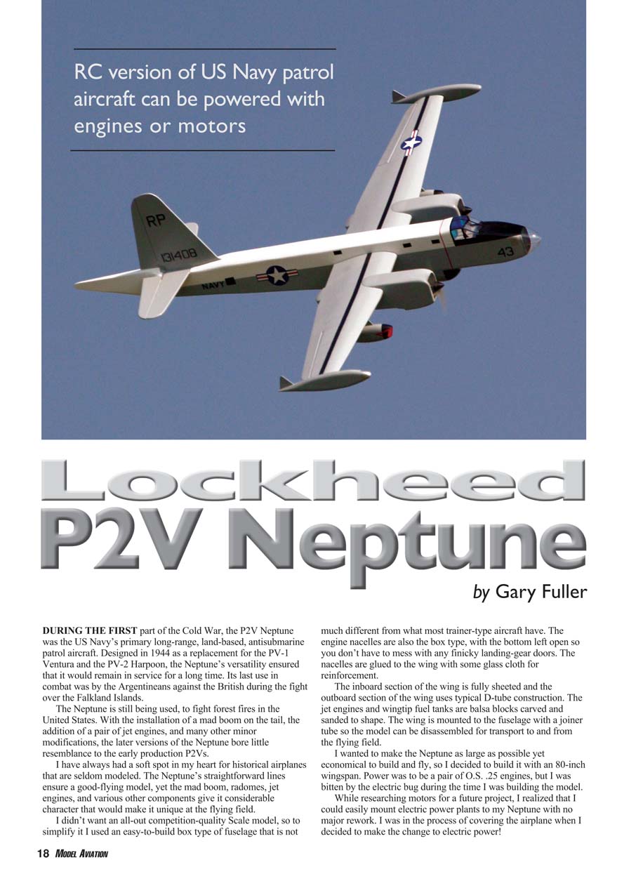
DURING THE FIRST part of the Cold War, the P2V Neptune was the US Navy’s primary long-range, land-based, antisubmarine patrol aircraft. Designed in 1944 as a replacement for the PV-1 Ventura and the PV-2 Harpoon, the Neptune’s versatility ensured that it would remain in service for a long time. Its last use in combat was by the Argentinians against the British during the fight over the Falkland Islands.
The Neptune is still being used to fight forest fires in the United States. With the installation of a MAD boom on the tail, the addition of a pair of jet engines, and many other minor modifications, the later versions of the Neptune bore little resemblance to the early production P2Vs.
I have always had a soft spot in my heart for historical airplanes that are seldom modeled. The Neptune’s straightforward lines ensure a good-flying model, yet the MAD boom, radomes, jet engines, and various other components give it considerable character that would make it unique at the flying field.
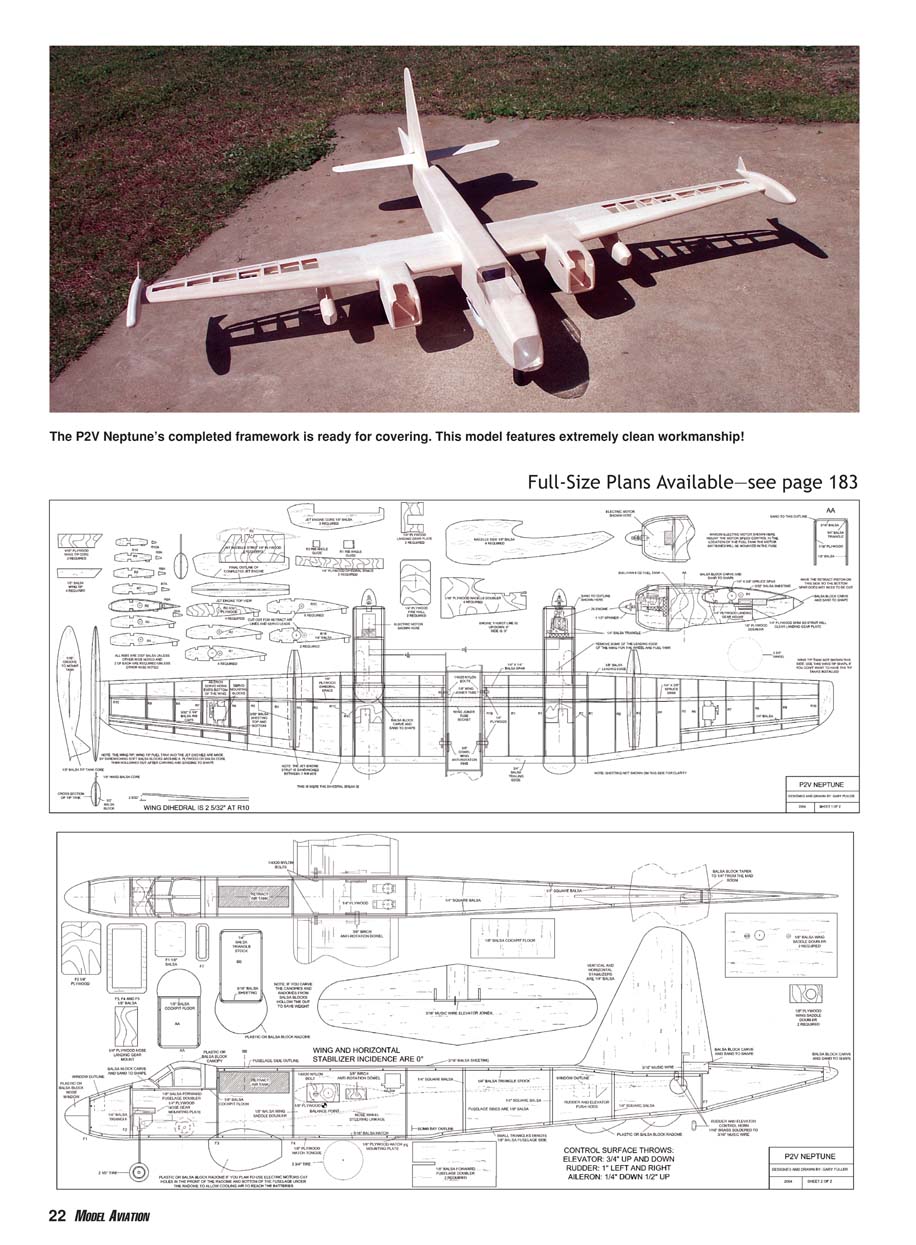
I didn’t want an all-out competition-quality scale model, so to simplify it I used an easy-to-build box type of fuselage that is not much different from what most trainer-type aircraft have. The engine nacelles are also the box type, with the bottom left open so you don’t have to mess with any finicky landing-gear doors. The nacelles are glued to the wing with some glass cloth for reinforcement. The inboard section of the wing is fully sheeted and the outboard section of the wing uses typical D-tube construction. The jet engines and wingtip fuel tanks are balsa blocks carved and sanded to shape. The wing is mounted to the fuselage with a joiner tube so the model can be disassembled for transport to and from the flying field.
I wanted to make the Neptune as large as possible yet economical to build and fly, so I decided to build it with an 80-inch wingspan. Power was to be a pair of O.S. .25 engines, but I was bitten by the electric bug during the time I was building the model. While researching motors for a future project, I realized that I could easily mount electric power plants to my Neptune with no major rework. I was in the process of covering the airplane when I decided to make the change to electric power!
I used a pair of MaxCim MaxN32-13Y motors direct drive spinning APC 10 x 5E propellers. The motor controllers are MaxCim MaxMu35D-21. I used 2000 mAh Kokam Li-Poly batteries wired 3S2P, for a total of 11.1 volts and 4000 mAh for each motor. That easily gave me a flight time exceeding 10 minutes with the motors throttled back and more than adequate power to take off from a grass field.
The retractable gear is the standard size, and normal modeling techniques are used to build the Neptune. If you have never built a model from plans, this should not be too difficult—especially if you have a few kits under your belt. Since this is not really a beginner’s airplane, I won’t go into much detail in the construction notes. I did not take any great pains to keep the weight down on my Neptune; I did not use contest-grade balsa, nor did I cut lightening holes in any of the sheet balsa. However, I am quite sure that if you used contest-grade wood and other weight-saving techniques, you could shave some weight from your Neptune.
CONSTRUCTION
I started my model by cutting all the parts and assembling them like a kit. If you have never built from plans, I recommend the following.
- To accurately cut small parts from wood:
- Cut the paper part shapes from the plans.
- Lightly spray the backside of a paper cutout with contact glue and let it dry for approximately 10 minutes until it is tacky.
- Place the paper shape on the wood and cut the wood with a band saw or a jigsaw.
- Remove the paper after you have cut the part.
- To cut more than one of the same part:
- Lightly spray both sides of some scrap paper with contact glue.
- Sandwich this paper between as many sheets of wood as necessary for the number of parts required.
- Cut the stack with a band saw or jigsaw.
- Separate each piece and remove the paper.
If you have never done this, try it on scrap wood and paper first. I have found that some brands of contact glue won't work because they are too tacky. I use carpet and headliner glue that comes in a spray can and is available in auto parts stores. A good alternative is an Elmer's school glue stick; it works as well without the mess.
Fuselage: The fuselage sides are too long and wide to cut from a single sheet of balsa, so you will need to splice some sheets together. I like to have the vertical splice where the wing doubler will reinforce the joint. Be careful with the sides until the doublers are installed. I like to lay the fuselage sides next to each other top to top as I glue on the various parts; that way I won't make two left or two right sides.
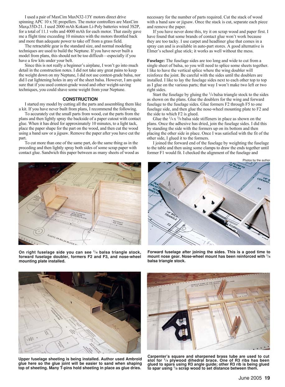
Start the fuselage by gluing the 1/4" balsa triangle stock to the sides as shown on the plans. Glue the doublers for the wing and forward fuselage to the fuselage sides. Glue formers F2 through F5 to one fuselage side, and then glue the nose-wheel mounting plate to F2 and to the side to which F2 is glued.
Glue the 1/4" x 3/8" balsa side stiffeners in place as shown on the plans. Once the adhesive has dried, join the fuselage sides. I did this by standing the side with the formers up on its bottom and then placing the other side in place. Once I was satisfied with the fit of the other side, I glued it to the formers.
I joined the forward end of the fuselage by weighting the fuselage to the table and then using some clamps to draw the ends together until former F1 would fit. I checked the alignment of the fuselage and adjusted until it was straight, and then I glued F1 in place. I joined the aft end of the fuselage in the same manner.
Glue the 1/4" balsa triangle to the nose-gear mount as shown on the plans. Mount the nose gear to its mounting plate with 4-40 screws and blind nuts. Glue the 1/8" plywood hatch mounting plate in place as shown on the plans. Install the 1/8" cockpit floor.
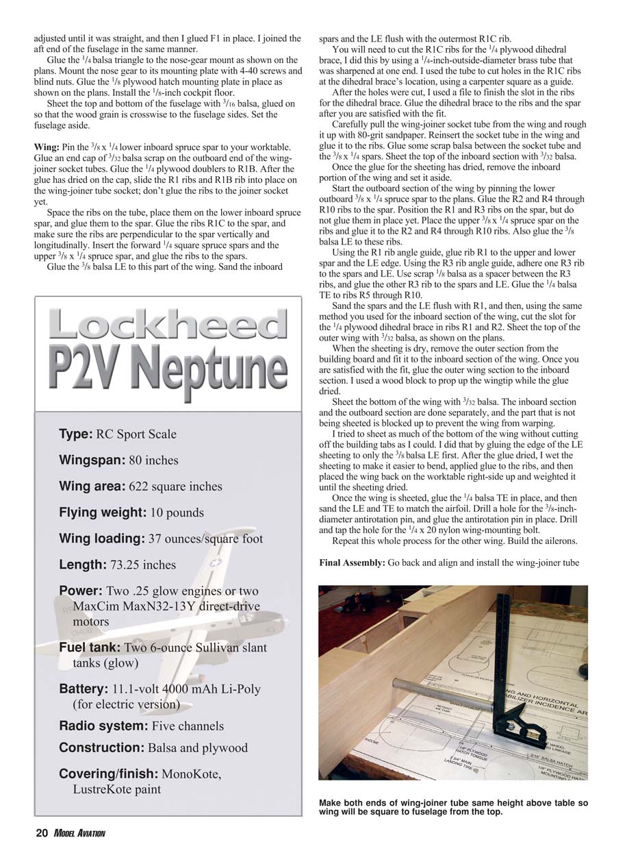
Sheet the top and bottom of the fuselage with 3/16" balsa, glued on so that the wood grain is crosswise to the fuselage sides. Set the fuselage aside.
Wing: Pin the 3/8" x 1/4" lower inboard spruce spar to your worktable. Glue an end cap of 3/32" balsa scrap on the outboard end of the wing-joiner socket tubes. Glue the 1/4" plywood doublers to R1B. After the glue has dried on the cap, slide the R1 ribs and R1B rib into place on the wing-joiner tube socket; don't glue the ribs to the joiner socket yet.
Space the ribs on the tube, place them on the lower inboard spruce spar, and glue them to the spar. Glue the ribs R1C to the spar, and make sure the ribs are perpendicular to the spar vertically and longitudinally. Insert the forward 1/4" square spruce spars and the upper 3/8" x 1/4" spruce spar, and glue the ribs to the spars.
Glue the 3/8" balsa LE to this part of the wing. Sand the inboard spars and the LE flush with the outermost R1C rib.
You will need to cut the R1C ribs for the 1/4" plywood dihedral brace. I did this by using a 3/8" outside-diameter brass tube that was sharpened at one end. I used the tube to cut holes in the R1C ribs at the dihedral brace's location, using a carpenter's square as a guide.
After the holes were cut, I used a file to finish the slot in the ribs for the dihedral brace. Glue the dihedral brace to the ribs and the spar after you are satisfied with the fit.
Carefully pull the wing-joiner socket tube from the wing and rough it up with 80-grit sandpaper. Reinsert the socket tube in the wing and glue it to the ribs. Glue some scrap balsa between the socket tube and the 3/8" x 1/4" spars. Sheet the top of the inboard section with 3/32" balsa.
Once the glue for the sheeting has dried, remove the inboard portion of the wing and set it aside.
Start the outboard section of the wing by pinning the lower outboard 3/8" x 1/4" spruce spar to the plans. Glue the R2 and R4 through R10 ribs to the spar. Position the R1 and R3 ribs on the spar, but do not glue them in place yet. Place the upper 3/8" x 1/4" spruce spar on the ribs and glue it to the R2 and R4 through R10 ribs. Also glue the 3/8" balsa LE to these ribs.
Using the R1 rib angle guide, glue rib R1 to the upper and lower spar and the LE edge. Using the R3 rib angle guide, adhere one R3 rib to the spars and LE. Use scrap 1/8" balsa as a spacer between the R3 ribs, and glue the other R3 rib to the spars and LE. Glue the 1/4" balsa TE to ribs R5 through R10.
Sand the spars and the LE flush with R1, and then, using the same method you used for the inboard section of the wing, cut the slot for the 1/4" plywood dihedral brace in ribs R1 and R2. Sheet the top of the outer wing with 3/32" balsa, as shown on the plans.
When the sheeting is dry, remove the outer section from the building board and fit it to the inboard section of the wing. Once you are satisfied with the fit, glue the outer wing section to the inboard section. I used a wood block to prop up the wingtip while the glue dried.
Sheet the bottom of the wing with 3/32" balsa. The inboard section and the outboard section are done separately, and the part that is not being sheeted is blocked up to prevent the wing from warping.
I tried to sheet as much of the bottom of the wing without cutting off the building tabs as I could. I did that by gluing the edge of the LE sheeting to only the 3/8" balsa LE first. After the glue dried, I wet the sheeting to make it easier to bend, applied glue to the ribs, and then placed the wing back on the worktable right-side up and weighted it until the sheeting dried.
Once the wing is sheeted, glue the 1/4" balsa TE in place, and then sand the LE and TE to match the airfoil. Drill a hole for the 3/8" diameter antirotation pin, and glue the antirotation pin in place. Drill and tap the hole for the 1/4-20 nylon wing-mounting bolt.
Repeat this whole process for the other wing. Build the ailerons.
Final Assembly: Go back and align and install the wing-joiner tube socket in the fuselage. Flip the fuselage upside down on the worktable and secure it so it won't move. Glue one of the 1/8" plywood joiner doublers inside one side of the fuselage.
Rough up the outside of the joiner tube socket with some sandpaper, and insert the socket into the fuselage. Slip the other 1/8" plywood joiner doubler onto the socket as you insert it into the fuselage, but don't glue the socket or the doubler to the fuselage yet.
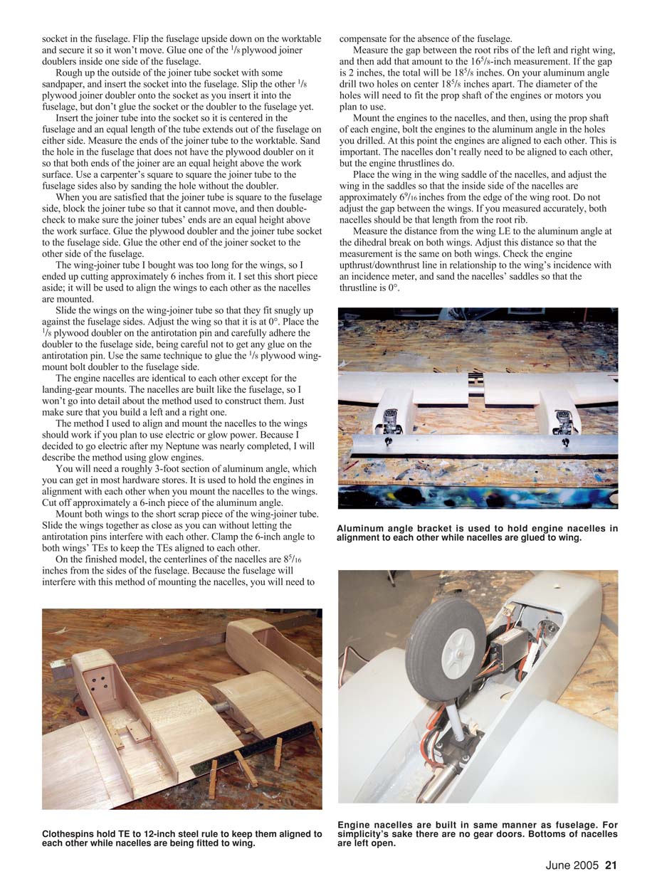
Insert the joiner tube into the socket so it is centered in the fuselage and an equal length of the tube extends out of the fuselage on either side. Measure the ends of the joiner tube to the worktable. Sand the hole in the fuselage that does not have the plywood doubler on it so that both ends of the joiner are an equal height above the work surface. Use a carpenter's square to square the joiner tube to the fuselage sides also by sanding the hole without the doubler.
When you are satisfied that the joiner tube is square to the fuselage side, block the joiner tube so that it cannot move, and then double-check to make sure the joiner tubes' ends are an equal height above the work surface. Glue the plywood doubler and the joiner tube socket to the fuselage side. Glue the other end of the joiner socket to the other side of the fuselage.
The wing-joiner tube I bought was too long for the wings, so I ended up cutting approximately 6 inches from it. I set this short piece aside; it will be used to align the wings to each other as the nacelles are mounted.
Slide the wings on the wing-joiner tube so that they fit snugly up against the fuselage sides. Adjust the wing so that it is at 0°. Place the 1/8" plywood doubler on the antirotation pin and carefully adhere the doubler to the fuselage side, being careful not to get any glue on the antirotation pin. Use the same technique to glue the 1/8" plywood wing-mount bolt doubler to the fuselage side.
The engine nacelles are identical to each other except for the landing-gear mounts. The nacelles are built like the fuselage, so I won't go into detail about the method used to construct them. Just make sure that you build a left and a right one.
The method I used to align and mount the nacelles to the wings should work if you plan to use electric or glow power. Because I decided to go electric after my Neptune was nearly completed, I will describe the method using glow engines.
You will need a roughly 3-foot section of aluminum angle, which you can get in most hardware stores. It is used to hold the engines in alignment with each other when you mount the nacelles to the wings. Cut off approximately a 6-inch piece of the aluminum angle.
Mount both wings to the short scrap piece of the wing-joiner tube. Slide the wings together as close as you can without letting the antirotation pins interfere with each other. Clamp the 6-inch angle to both wings' TEs to keep the TEs aligned to each other.
On the finished model, the centerlines of the nacelles are 8 5/16" from the sides of the fuselage. Because the fuselage will interfere with this method of mounting the nacelles, you will need to compensate for the absence of the fuselage.
Measure the gap between the root ribs of the left and right wing, and then add that amount to the 16 5/8" measurement. If the gap is 2", the total will be 18 5/8". On your aluminum angle drill two holes on center 18 5/8" apart. The diameter of the holes will need to fit the prop shaft of the engines or motors you plan to use.
Mount the engines to the nacelles, and then, using the prop shaft of each engine, bolt the engines to the aluminum angle in the holes you drilled. At this point the engines are aligned to each other. This is important. The nacelles don't really need to be aligned to each other, but the engine thrustlines do.
Place the wing in the wing saddle of the nacelles, and adjust the wing in the saddles so that the inside side of the nacelles are approximately 6 9/16" from the edge of the wing root. Do not adjust the gap between the wings. If you measured accurately, both nacelles should be that length from the root rib.
Measure the distance from the wing LE to the aluminum angle at the dihedral break on both wings. Adjust this distance so that the measurement is the same on both wings. Check the engine upthrust/downthrust line in relationship to the wing's incidence with an incidence meter, and sand the nacelles' saddles so that the thrustline is 0°.
Full-Size Plans Available—see page 183
Once you are satisfied with all of these measurements, tack-glue the nacelles to the wings. Flip the wings over so you can glue the nacelles to the wing with epoxy and glass cloth on the inside of the nacelles. Carefully unbolt the engines from the aluminum angle and then separate the wings from each other.
Install the wires to the fuselage, and mount the horizontal stabilizer so it is at 0° incidence to the wing. Mount the vertical stabilizer.
It is time to start all the little details such as the dummy jet engines, the wingtip tanks, the radomes, and the canopy. I made my canopy and the forward observer’s canopy on the nose from clear plastic, but you can carve and sand a balsa block to shape if you want.
To supply some cooling air for the batteries, I vacuum-formed the big radome on the bottom of the fuselage from plastic. On the front of the radome I cut some holes, and on the bottom of the fuselage I cut holes where the radome mounts. This allows the radome to act like a big air scoop to cool the batteries. I cut holes on the back end of the fuselage hatch to allow the air to escape.
Radio Installation
This is fairly straightforward. I used some flat wing servos for the ailerons, and these needed to be installed before I covered the wing. Before I decided to switch to electric power, each engine was to have had a separate throttle servo that I planned to mount behind the main landing gear in the nacelles.
I mounted the elevator, rudder, and retract servos in the fuselage. An important thing here is to make sure you have clear access to the wing-mounting bolts in the fuselage. Otherwise, mount the radio gear as you see fit. After test-flying I found that aileron differential is recommended along with some rudder mixed into the ailerons.
Since this was my first electric-powered twin, I decided to use one motor controller and a separate battery pack for each motor, and a servo “Y” harness to connect the motor controllers to the receiver. I also used a separate battery to power the receiver and servos.
The fuel tanks need special attention because the main landing gear will fold up next to the tanks, and it is a tight fit. You will need narrow tires and narrow fuel tanks, for which I planned to use Sullivan 6-ounce slant oval fuel tanks.
I also planned something different to mount the fuel tanks. After the model was finished and the nacelles were fuel-proofed, I simply RTVed (room-temperature vulcanized) the tanks to the inside of the nacelles. Rough up the side of the fuel tank with 80-grit sandpaper if you try this.
I mounted the ESCs for the motors using Velcro in the place where I was going to mount the fuel tanks. Using more Velcro, I mounted the retract air tank to the inside top of the fuselage just behind the cockpit.
Finishing
I covered my model with MonoKote in the color scheme that US Navy patrol squadrons used in the 1960s. If you want a more visible scheme, you could try one with a red tail that the naval reserve squadrons used or use the colors that are on some of the forest-fire-fighting versions. Some Neptunes were used to launch drones and missiles and had highly visible appearances. There is much information about this airplane on the Internet.
I sanded the dummy jet engines and tip tanks smooth and filled the grain, and then I painted them with LustreKote. All of the markings are trim MonoKote.
For those who plan to use glow engines, I will describe the method I have used on my previous glow-powered, twin-engine models to set up the power plants. Before you fly your airplane, make sure both engines are properly adjusted on the ground so that they are reliable. I don’t bother to get them synchronized to each other; I try to get them to run dependably.
I set each engine independently for a reliable idle with a smooth transition to high speed. I set the high-speed needle by pinching the fuel line and noting a slight rise in the rpm without the engine dying. I point the model’s nose straight up and straight down to see if the engine sags or dies. I also do this with the engine at idle.
Once I have both engines running reliably at a time, I run both at the same time and check each engine using the same methods. I do all of this at home so I don’t feel pressured to fly the model. This also gives me a chance to make sure nothing shakes loose.
I'm right-handed, so I start the left engine first on my twins. This makes it easier to stay out of the way of the left engine while I start the right engine.
Flying
I balanced my Neptune 2 7/8" behind the wing's LE. After test-flying, I feel that this is probably the farthest aft I recommend to balance the model for good, smooth flying.
I had to wait what seemed like forever for the weather to cooperate—it was either too windy or raining—but I was finally able to sneak out early in the morning and test-fly my Neptune before the wind picked up. After I assembled it at the field, I did a range check of the radio with the motors running.
I taxied the model to the end of the runway and pointed it into the wind. I advanced the throttles, and, after roughly 150 feet I started to ease in some up-elevator. I was pleasantly surprised when the airplane gently rotated and started to climb out at a nice, realistic climb rate.
It seemed to be flying well, so I flipped the landing-gear switch, only to be dismayed to see just the nose wheel and the left main wheel retract. I flipped the gear switch to the down position, and the nose wheel came down and the left main wheel stayed up!
I wasn't going to let this ruin my test flight, so I continued by climbing the model to altitude to check the trims. My Neptune required only some up-trim with the throttles pulled back to a realistic cruise speed.
After cruising around for a few minutes, I throttled down to check the stall characteristics. My Neptune slowed better than I expected, but it had a sharp stall. If you build one, keep the airspeed up on the landing approach. I did a few low passes down the runway and then I tried a few practice approaches.
When I finally decided to land the Neptune, I was able to put it down gently, but the nose gear collapsed and it skidded down the runway on the radome and left dummy jet engine. I was surprised that the nacelle and the radome held up (I thought they were going to be destroyed), but my Neptune ended up with only some paint scraped off the radome and the left jet engine.
After learning that the landing-gear air valve had a small leak, I locked the gear down and did one more flight that day with no problems. My model ended up weighing just less than 10 pounds ready to fly, which was slightly heavier than I wanted, but the motors provide more than enough power for flight.
The Neptune's glide is a tad steep, but I suppose two propellers windmilling creates quite a bit of drag. Carry some power on the landing approach, and as the Neptune gets near the ground, slowly reduce power and bleed the airspeed off with the elevator. With practice you should be able to grease it on the mains and roll out a short distance before the nose wheel comes down.
Final Thoughts
This has been one of the most enjoyable models I have built in a while. It went together much better than I expected; the flight characteristics are better than I expected, and it looks great in the air. The last-minute conversion to electric power was a good move, and it has convinced me that this is the way to go on my future airplanes.
MA
Gary Fuller 7076 E. Heather Dr. Claremore, OK 74019 [email protected]
Transcribed from original scans by AI. Minor OCR errors may remain.

