
Lofting Techniques
Roy Day
Suppose you want to design a Sport Scale airplane, or an original that's a bit different from the "box with a wing." Say you'd like to design an airplane with an oval cross-section fuselage and tapered wings. Furthermore, you don't have a computer or Computer Aided Drafting (CAD) capability. No problem. There are simple techniques that have been in use for years, long before the advent of the computer and CAD programs.
The method is called lofting. Lofting was used hundreds of years ago by ship designers to lay out hulls. It applies equally well to aircraft design.
Lofting is a technique of drawing a family of shapes that will result in a smooth outside form. It can be used to generate the formers for any cross-section fuselage and the ribs for a tapered wing. It can also be used to design cowls and canopies.
When we design a scale model from scratch, the starting place is a three-view drawing of the full-scale airplane. Unless you are lucky, many three-views only give you the airplane outlines and maybe two or three fuselage cross-sections. You will need to draw the remainder of the formers, as well as the ribs for your tapered wing.
Follow the steps shown and see how easy it is.
Fuselage
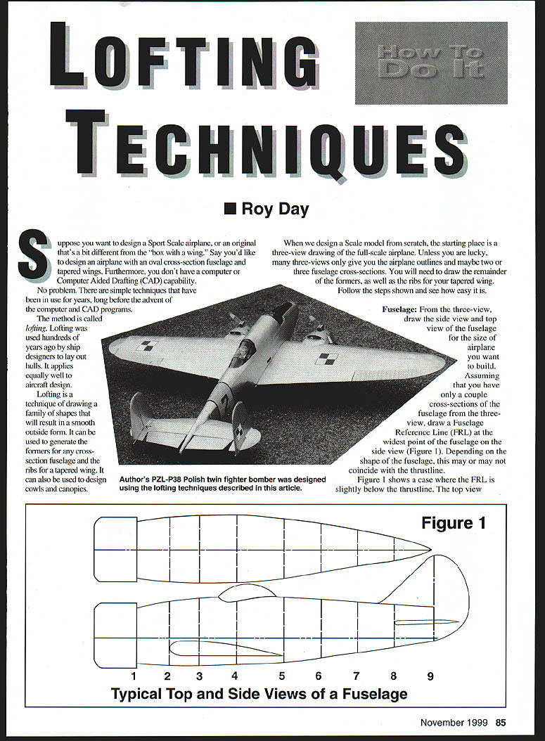
From the three-view, draw the side view and top view of the fuselage for the size of airplane you want to build. Assuming that you have only a couple of cross-sections of the fuselage from the three-view, draw a Fuselage Reference Line (FRL) at the widest point of the fuselage on the side view (Figure 1). Depending on the shape of the fuselage, this may or may not coincide with the thrustline. Figure 1 shows a case where the FRL is slightly below the thrustline. The top-view outline should be aligned with the FRL — that is, the widest part of the fuselage. If you use the crutch method to build, you can build the upper or lower half of the fuselage over the top view.
Assume that you are given only two cross-sections from the three-view: the firewall and one at the cockpit location (stations 1 and 4 on Figure 1). You will also need formers at the wing leading edge, trailing edge, leading edge of the stabilizer, and others to complete the fuselage and to give the skin/covering a smooth contour.
For this example, the fuselage is shown with nine stations, including the rudder post. These stations are drawn on the side and top views as shown in Figure 1.
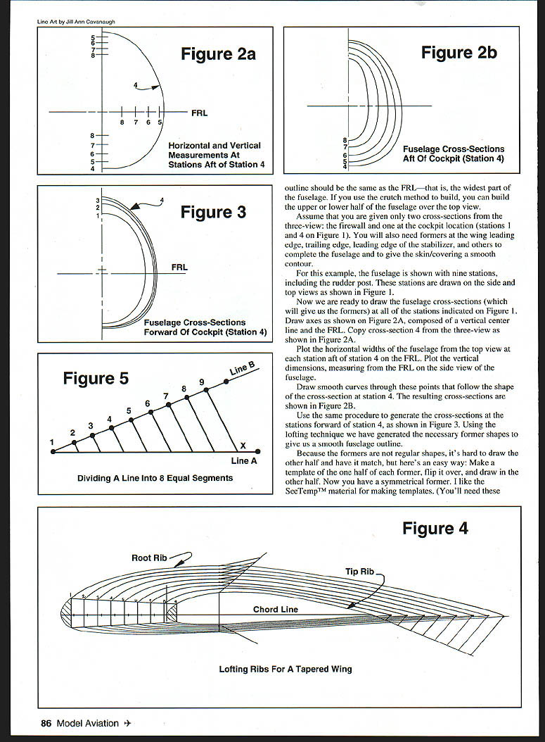
Now we are ready to draw the fuselage cross-sections (which will give us the formers) at all of the stations indicated on Figure 1. Draw axes as shown on Figure 2A, composed of a vertical center line and the FRL. Copy cross-section 4 from the three-view as shown in Figure 2A.
Plot the horizontal widths of the fuselage from the top view at each station aft of station 4 along the FRL. Plot the vertical dimensions, measuring from the FRL on the side view of the fuselage.
Draw smooth curves through these points that follow the shape of the cross-section at station 4. The resulting cross-sections are shown in Figure 2B.
Use the same procedure to generate the cross-sections at the stations forward of station 4, as shown in Figure 3. Using the lofting technique we have generated the necessary former shapes to give us a smooth fuselage outline.
Because the formers are not regular shapes, it's hard to draw the other half and have it match. Here's an easy way: make a template of one half of each former, flip it over, and draw in the other half. Now you have a symmetrical former. I like the SeeTemp™ material for making templates.
Tapered Wing Ribs
Lay down the chord line and draw the root rib. Place the tip rib as determined by the wing taper (Figure 4). To make the method easy, space the ribs equally along the span. Divide the vertical and horizontal space between the root and tip ribs by the number of ribs (nine in this case).
Here's a little trick for dividing an arbitrary length line into a number of equal parts (see Figure 5). To divide a line into eight equal parts:
- Draw line B at an acute angle to line A (the line to be divided).
- Divide line B into eight convenient equal segments.
- Connect the far end point on line B (point 9) to the far end of line A (point X).
- From each division point on line B, draw lines parallel to the line 9–X.
- These parallels will intersect line A and divide it into the required eight equal segments.
This same method is used to divide the horizontal and vertical spaces between the tip and root ribs in Figure 4.
Using a French curve or ship's curve, draw the remaining ribs. Spars can also be located as shown in Figure 4. Spar notches can be cut in the ribs. Note that no washout is indicated on the lofted ribs — washout will be introduced during building.
Roy Day
11709 Magruder Ln Rockville, MD 20852
Transcribed from original scans by AI. Minor OCR errors may remain.

