
Lotsa Amps
by Dick Sarpolus
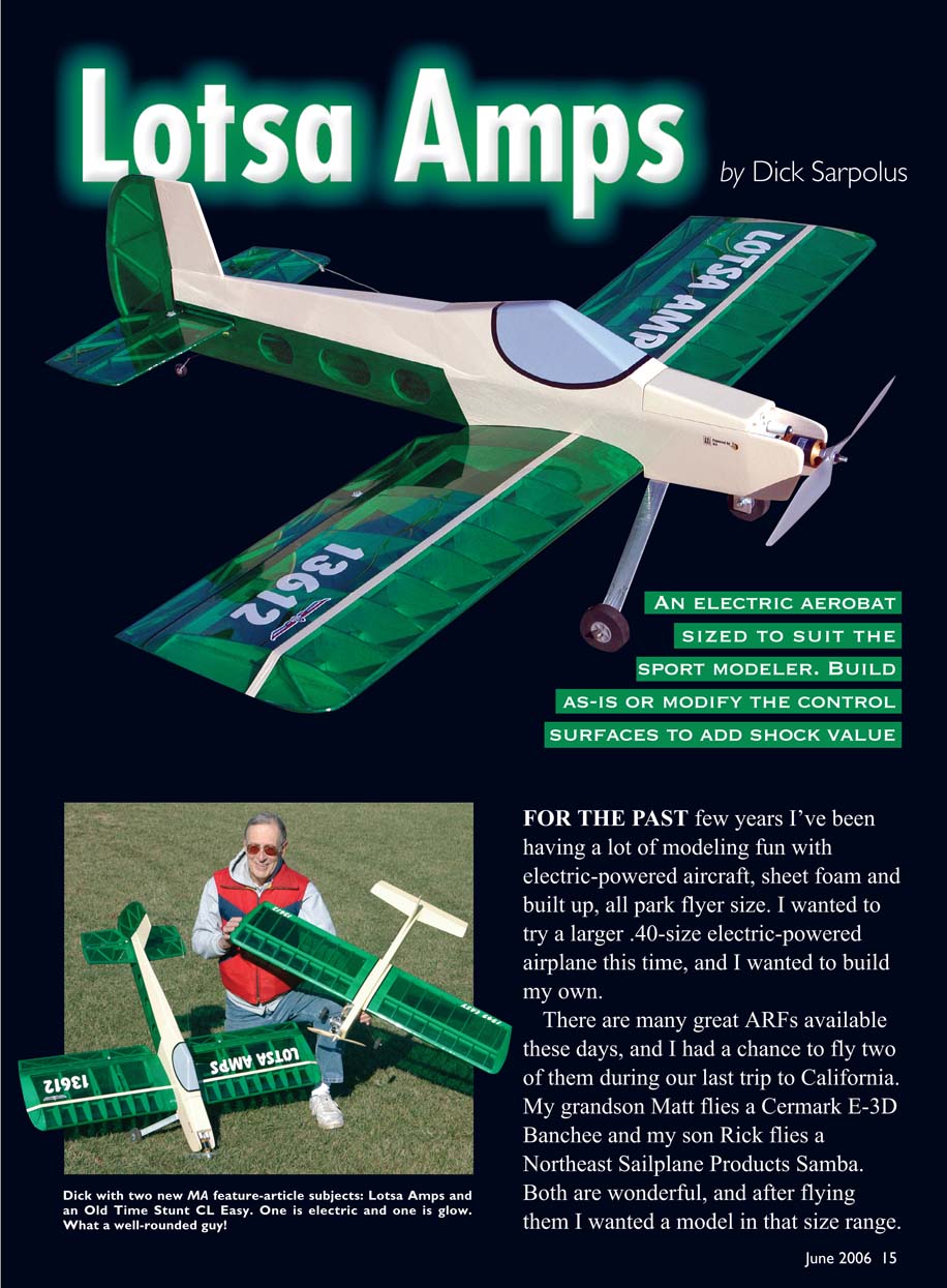
For the past few years I’ve been having a lot of modeling fun with electric-powered aircraft, sheet-foam and built-up, all park-flyer size. I wanted to try a larger .40-size electric-powered airplane this time, and I wanted to build my own.
There are many great ARFs available these days, and I had a chance to fly two of them during our last trip to California. My grandson Matt flies a Cermark E-3D Banchee and my son Rick flies a Northeast Sailplane Products Samba. Both are wonderful, and after flying them I wanted a model in that size range.
ARFs make a great deal of economical sense, but I like to make balsa sawdust and wood chips when I build. I knew I couldn't make an airplane as light as most of the ARFs, but I wanted one that was a bit more rugged, to withstand those rough landings and occasional tumbles. I also wanted good aerobatic capability but not necessarily the 3-D stuff—a reflection of my flying style, I guess. So I went to the drafting board.
For a long time .40 has been the best-selling engine size; I'm sure because so many trainers are powered by .40s and many sport, aerobatic, and fun-fly aircraft are made for this size engine. I was interested in seeing how electric power compared to the .40 glow engines I'd become accustomed to using for so many years.
I laid out a 54-inch-span wing with 675 square inches of wing area, a constant chord for easy building, and a nice, thick symmetrical airfoil. This is the size of airplane I'd normally power with a good .40 or .45 glow engine.
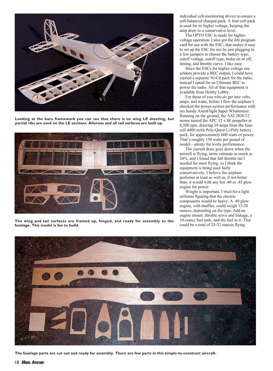
For a lighter-weight wing I spaced the ribs farther apart than usual and didn't use leading-edge planking, but I did put in partial ribs ahead of the spars. All the control surfaces are built up, again to save weight. The control surfaces are large but not huge.
The fuselage is a basic sheet-balsa box with some lightening holes. I did use plywood doublers in the forward section, with lightening holes and a sturdy landing-gear mount. The one-piece wing bolts to the fuselage. I left out the plastic canopy and plastic nose cowl to keep things easy.
Using Electric Power
With modern electric-power technology in mind, I knew I wanted a brushless motor and Li-Poly batteries for plenty of performance and the lightest possible weight. Many power systems could be used. I found the Hobby Lobby web site extremely helpful, with its practical information about motors, controllers, and batteries that the company has used for electric conversions of many glow-powered aircraft.
Reviewing the equipment Hobby Lobby chose for the different airframes and the practical information provided with the motor specifications helped in my selections. I could compare the size and weight of my new project with a number of similar aircraft. In addition, the company has knowledgeable people to answer questions about your modeling projects; they sure helped me.
How to select a motor, propeller, and battery still seems mysterious to me. When we pick a glow engine we don't have to get into dynamometer testing for horsepower figures, so I prefer not to get into too much volts, amps, and watts stuff. I'd rather know that a motor will turn a certain propeller at an rpm with a particular battery-pack rating, and I can buy hardware expecting it to fly my size of airplane.
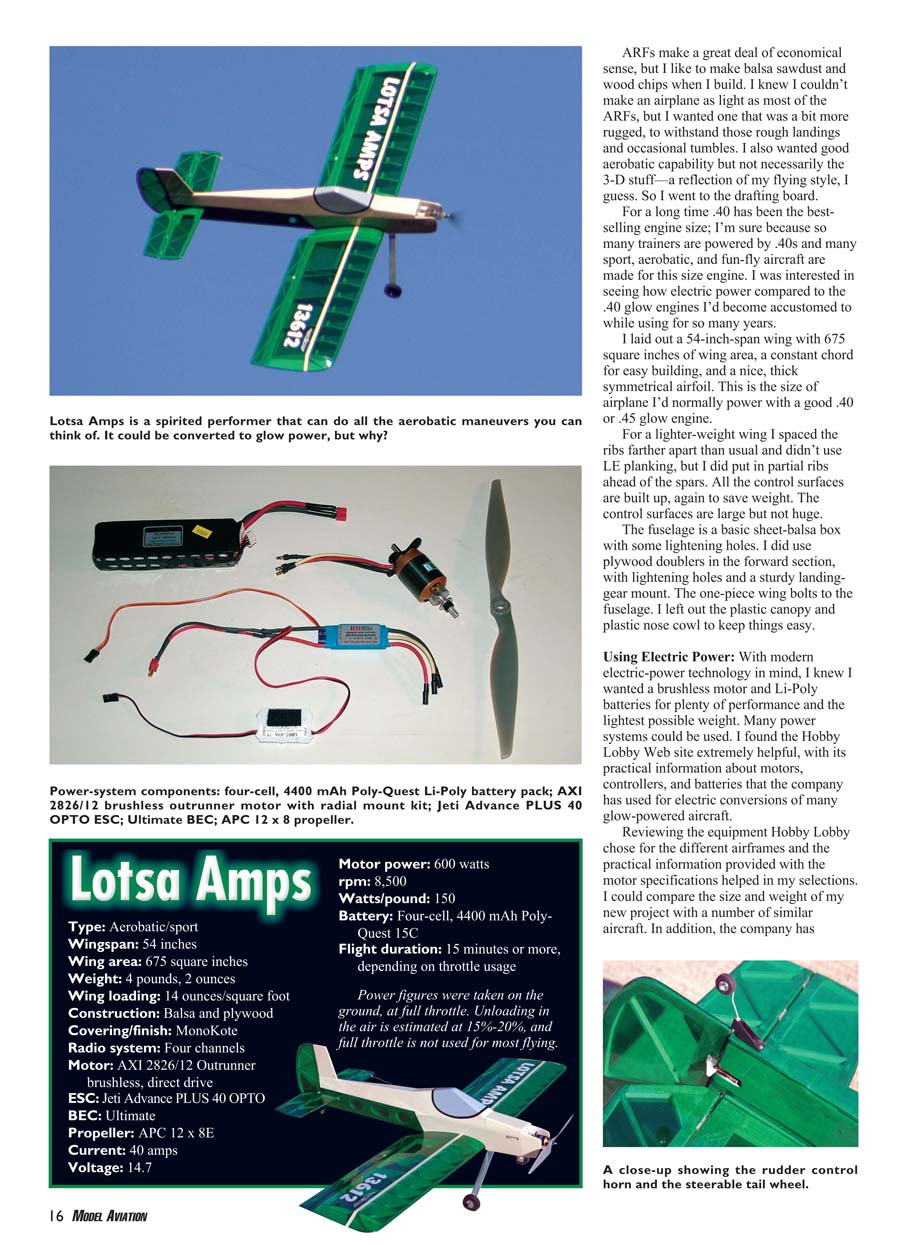
From the Hobby Lobby data, and after talking with Mike Hines for advice, I selected the following hardware for this project:
- Motor: AXI 2826/12 Outrunner brushless direct-drive motor
- ESC: Jeti Advance PLUS 40 OPTO ESC
- Propeller: APC 12 x 8E electric propeller
- Battery: Poly-Quest 4S1P 4400 mAh Li-Poly pack
That is a newer-generation battery with heavier discharge capability, and it is a lightweight unit. I liked the idea of the individual cell-monitoring device to ensure a cell-balanced charged pack. A four-cell pack is used for its higher voltage, keeping the amp draw to a conservative level.
The OPTO ESC is made for higher-voltage operation. I also got the Jeti program card for use with the ESC; that makes it easy to set up the ESC by just plugging in a few jumpers to choose battery type, cutoff voltage, cutoff type, brake on or off, timing, and throttle curve. I like easy.
Since the ESCs for higher-voltage use seldom provide a BEC output, I could have carried a separate Ni-Cd pack for the radio; instead I opted for an Ultimate BEC to power the radio. All of that equipment is available from Hobby Lobby.
For those of you who do get into volts, amps, and watts, before I flew the airplane I checked the power-system performance with my AstroFlight Super WATTMeter. Running on the ground, the AXI 2826/12 motor turned the APC 12 x 8E propeller at 8,500 rpm, drawing 39 amps from the four-cell 4400 mAh Poly-Quest Li-Poly battery pack, for approximately 600 watts of power. That's roughly 150 watts per pound of model—plenty for lively performance.
The current draw goes down when the aircraft is flying, some estimate as much as 20%, and I found that full throttle isn't needed for most flying, so I think the equipment is being used fairly conservatively. I believe the airplane performs at least as well as, if not better than, it would with any hot .40 or .45 glow engine for power.
Weight is important. I tried for a light airframe figuring that the electric components would be heavy. A .40 glow engine, with muffler, could weigh 13–20 ounces, depending on the type. Add an engine mount, throttle servo and linkage, a 10-ounce fuel tank, and the fuel in it. That could be a total of 25–32 ounces flying weight. That surprised me.
For the electric hardware figure roughly 7 ounces for the motor, 3 ounces for the ESC and BEC, and 14 ounces for the battery. That's approximately 24 ounces. Okay, so maybe this .40-size electric stuff isn't so heavy. And maybe my figures aren't so accurate, but it seems that with modern technology, brushless motors, and Li-Poly batteries, electric power can weigh roughly the same as glow-engine power.
The biggest difference between electric and glow power is the speed the propeller is turned and the propeller sizes used. An average .40 engine would likely use a 10 x 6 propeller. With my AXI motor I've tried a 12 x 8, 13 x 8, and 13 x 6.5 so far, and I am still experimenting. Sure, the motor turns slower than a glow engine, but it turns a bigger propeller.
The model doesn't care too much. Many of the glow-engine-horsepower ratings are made at higher speeds than these engines will ever see in most sport-model usage, so those high rpm and horsepower numbers don't mean much.
I used four Hitec HS-85BB servos. They are small, light, and powerful.
The airplane at the completed-but-uncovered-framework stage without power plant and radio equipment weighed approximately 2 pounds. Covered and with the motor, controller, battery pack, and radio gear, the total weight was 4 pounds, 2 ounces, for a wing loading of 14 ounces per square foot of wing area. I consider that a great figure for a sport-flying, aerobatic aircraft.
Test flights were uneventful except for the large amount of power available. I was immediately comfortable with the airplane—well, at a lower throttle setting and after adjusting the dual-rate settings on the transmitter to get the control response I liked and could handle.
This model has plenty of power for easy takeoffs from the grass fields I fly from and ample power for all the aerobatics I can think of. Most of the time I'm flying at considerably less than full throttle, and I like to make several shorter flights on one charged pack. It looks as though 15-minute-plus flights are no problem. You can probably make them longer, depending on your power usage.
I know I'll be burning less glow fuel and gas in the future. I'll also be spending more money on electric-power gear.
I charge my Li-Poly batteries with an AstroFlight Lithium Charger and use a 10-amp DC power supply to run the charger in my workshop. Since the PolyQuest Li-Poly battery packs are equipped with a plug that has leads from each cell, I use the Poly-Quest Protective Circuit Module (PCM) Guards when charging them.
The PCM Guard is a protective device that cuts off the charger when the first cell in the pack reaches 4.2 volts; this doesn't balance all the cells, but it does assure that no particular cell will be charged past the 4.2-volt safe upper limit. It seems like a good idea.
For those of you who like to scratch-build your airplanes, you can follow my plans or incorporate your ideas for modifications as you build. If you want to aim for more 3-D flying, increase the aileron area by widening their chord. If you think the tail control surfaces could be larger, make them larger. If you can put more lightening holes in the structure, do it. If you want to use thinner plywood doublers, go ahead.
An interesting modification would be to move the wing location higher on the fuselage and have separate wing panels sliding onto an aluminum tube spar/joiner. As scratch builders we can do what we want. Following are some building notes.
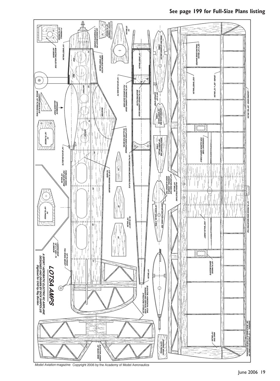
Construction
I obtain an extra copy of the plans I can cut up to get the parts patterns, along with the wing and tail-surface layouts I use to build the parts over. Paper parts patterns aren't bad to work with. I draw around them on the plywood or balsa with a ballpoint pen and then cut the pieces with a band saw or scroll saw.
Wing
I usually start here, placing the lower spar over the plans and using weights to keep it in place, using waxed paper to protect the plans and work surface. The ribs are placed on the lower spar and held up off the table with a balsa strip placed toward the rear of the wing layout.
With the ribs glued in place, follow them with the top spar, leading edge, trailing-edge sheeting, and partial ribs. The trailing edge has to be planed and sanded to shape; it's a pain, but there are only two pieces needed. I wait to add the center-section sheeting until the wing halves are joined. I don't think dihedral hurts the aerobatic capability, but join the panels without dihedral if you prefer a flat wing.
Don't forget the cardboard tubes for the aileron extension cables before you glue the wing halves together with the plywood joiner. I use a small amount of fiberglass cloth and epoxy around the leading- and trailing-edge center areas.
Tail Surfaces
Build the ailerons, stabilizer, fin, elevators, and rudder from 1/4-inch balsa strip stock over the plans, using your choice of glue. I do a great deal of building with five-minute epoxy; it seems like I'm always in a hurry to get it done.
Join the elevator halves with a piece of 1/8-inch-diameter music wire. Plane and block-sand the leading edges of the elevators, rudder, and ailerons to the beveled shape.
Use your choice of hinges. I employ the pinned nylon variety or the cyanoacrylate easy-hinge type.
Fuselage
Start the fuselage build-up by gluing the plywood doublers to the balsa side pieces. I put the lightening holes in the plywood with a hole saw in a small drill press. I glue the bulkheads at the leading- and trailing-edge positions to one of the sides, add the other side, and then add the remaining bulkheads.
Cut the upper side pieces oversize, to allow for the bevel that has to be sanded on the bottom edge before gluing those pieces in place. Because of the taper in the rear of the fuselage, the upper pieces have to be trimmed carefully to fit in place.
With the upper sides on I use a sanding block to bevel the top edges for the top sheeting. Add the top sheeting and round all the edges well.
Final Assembly
Fit the fuselage to the wing, align it, and get it bolted in place. Add the horizontal stabilizer, aligning it with the wing. The last step is to add the vertical fin.
With the control surfaces hinged in place, add the control horns and the linkage from the servos. I use either fiberglass-tube pushrods or flexible nylon-tube linkages. Glue plywood mounts for the aileron servos in place between the closely spaced ribs.
For easy access to the battery pack I have a removable front hatch with dowels in the rear for alignment and a nylon hold-down snap on the front end of the hatch. I left the motor exposed for easy access and mounted it to the firewall with 1-inch standoffs. I did this so there would be room for a geared motor setup if I ever want to try that sort of power plant.
Two washers on the left-side mounting bolts provide some right thrust. I considered shaping a foam or wood block for an enclosed motor cowl, maybe with two horizontal cheek-cowl shapes for styling, and laying up a fiberglass cowl. In the end I went with a simple sheet-balsa extension on each side of the motor area.
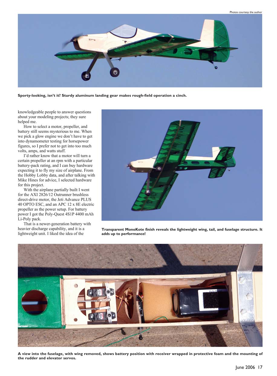
I made the landing gear from a 1-inch-wide, 1/8-inch-thick strip of 6061-T6 aluminum and used light foam wheels. The gear is held in place with three 1/4-inch nylon bolts. The mounting plate is secured in the fuselage; I've already ripped the gear off on a poor landing, and the only damage was the three broken nylon bolts.
A good source for aluminum landing gear is TNT Landing Gear Products at www.tntlandinggear.com. The steerable tail-wheel bracket is a standard molded nylon piece.
For final balancing of the airplane, there's enough room in the fuselage to move the battery pack to the rear or forward to get the balance point where you want it. I like to start with the model slightly nose-heavy and move the balance point to the rear to get the response I want.
If you use a motor and/or battery pack that is heavier than the equipment I used, you might want to shorten the nose a bit—maybe a half inch. Or you can install the elevator and rudder servos back near the tail surfaces.
Covering
I covered the airplane with MonoKote; I've used this material for many years. It took a lot of heating and tugging to get the wingtips free of wrinkles, so I might try some softer material on the next project.
Flying
I like the way this aircraft performs. It's not a contest machine. I wanted it to be a hot, fun flier—an aerobatically capable airplane but one I could relax with a bit. I notice that the older I get, the better I used to fly.
I'm glad I tried this .40-size electric. Although I won't be getting rid of those glow and gas burners, I expect to be doing more electric-powered projects in the future. Enjoy!
Dick Sarpolus [email protected]
Transcribed from original scans by AI. Minor OCR errors may remain.

