
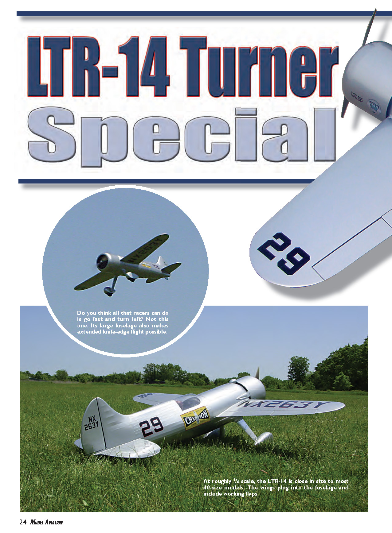
LTR-14 Turner Special
by Jim Young
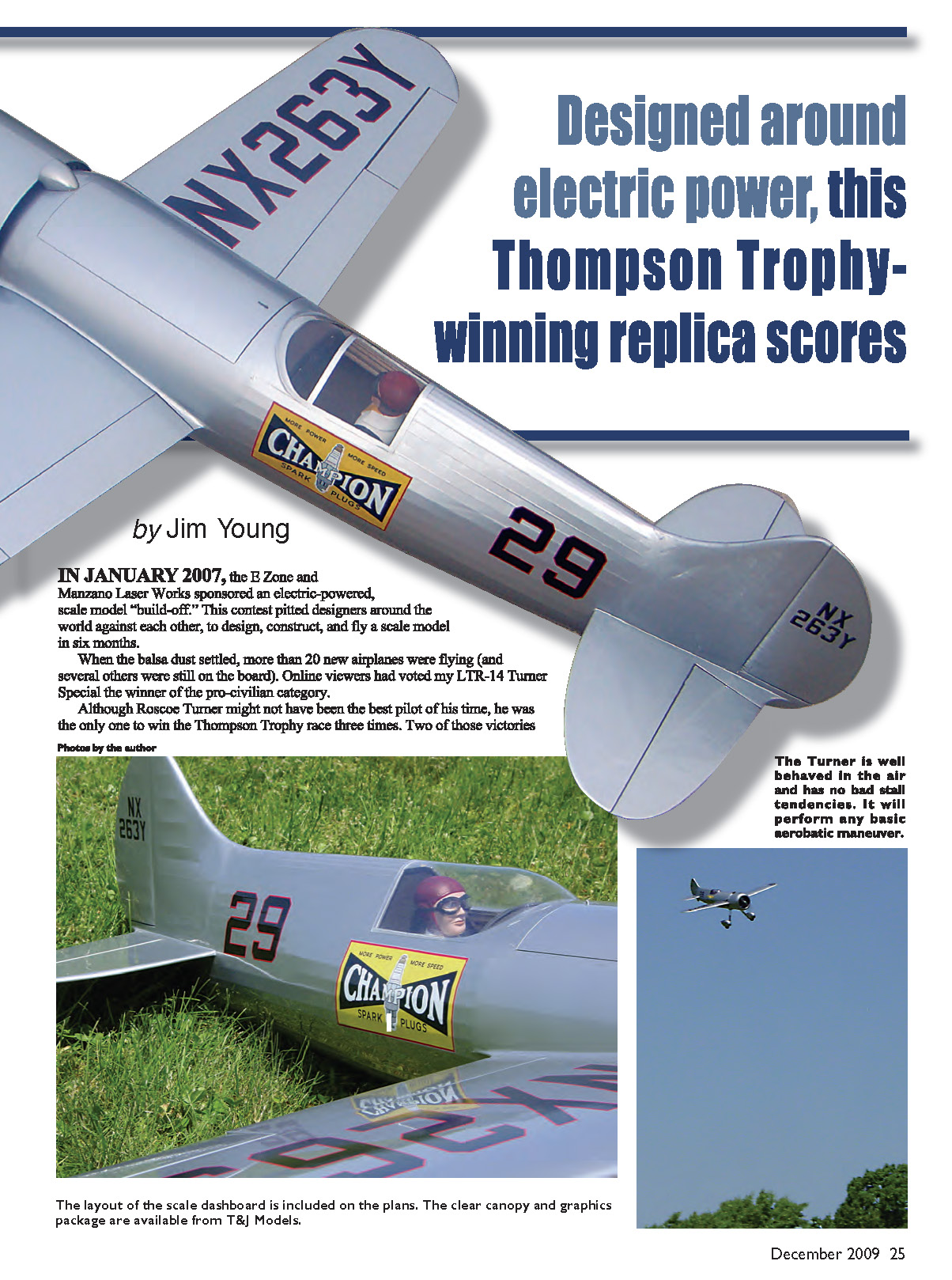
In January 2007, the E-Zone and Manzano Laser Works sponsored an electric-powered, scale-model "build-off." This contest pitted designers around the world against each other to design, construct, and fly a scale model in six months. When the balsa dust settled, more than 20 new airplanes were flying (and several others were still on the board). Online viewers had voted my LTR-14 Turner Special the winner of the pro-civilian category.
Although Roscoe Turner might not have been the best pilot of his time, he was the only one to win the Thompson Trophy race three times. Two of those victories were in the Turner Special.
The layout of the scale dashboard is included on the plans. The clear canopy and graphics package are available from T&J Models.
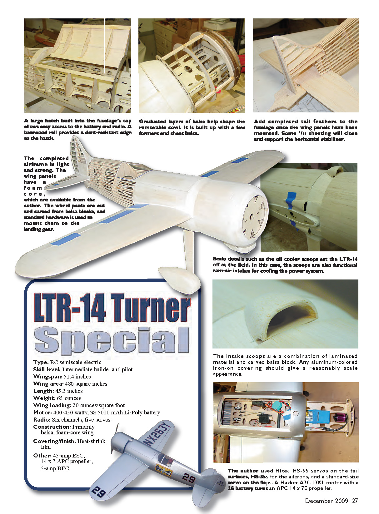
Designed around electric power, this Thompson Trophy–winning replica soars. The Turner is well behaved in the air and has no bad stall tendencies. It will perform any basic aerobatic maneuver. The completed airframe is light and strong. The wing panels have a foam core (which are available from the author). The wheel pants are cut and carved from balsa blocks, and standard hardware is used to mount them to the landing gear.
- Type: RC semiscale electric
- Skill level: Intermediate builder and pilot
- Wingspan: 51.4 inches
- Wing area: 480 square inches
- Length: 45.3 inches
- Weight: 65 ounces
- Wing loading: 20 ounces/square foot
- Motor: 400–450 watts; 3S 5000 mAh Li-Poly battery
- Radio: Six channels, five servos
- Construction: Primarily balsa, foam-core wing
- Covering/finish: Heat-shrink film
- Other: 45-amp ESC, 14 x 7 APC propeller, 5-amp BEC
The author used Hitec HS-65 servos on the tail surfaces, HS-55s for the ailerons, and a standard-size servo on the flaps. A Hacker A30-10XL motor with a 3S battery turns an APC 14 x 7E propeller.
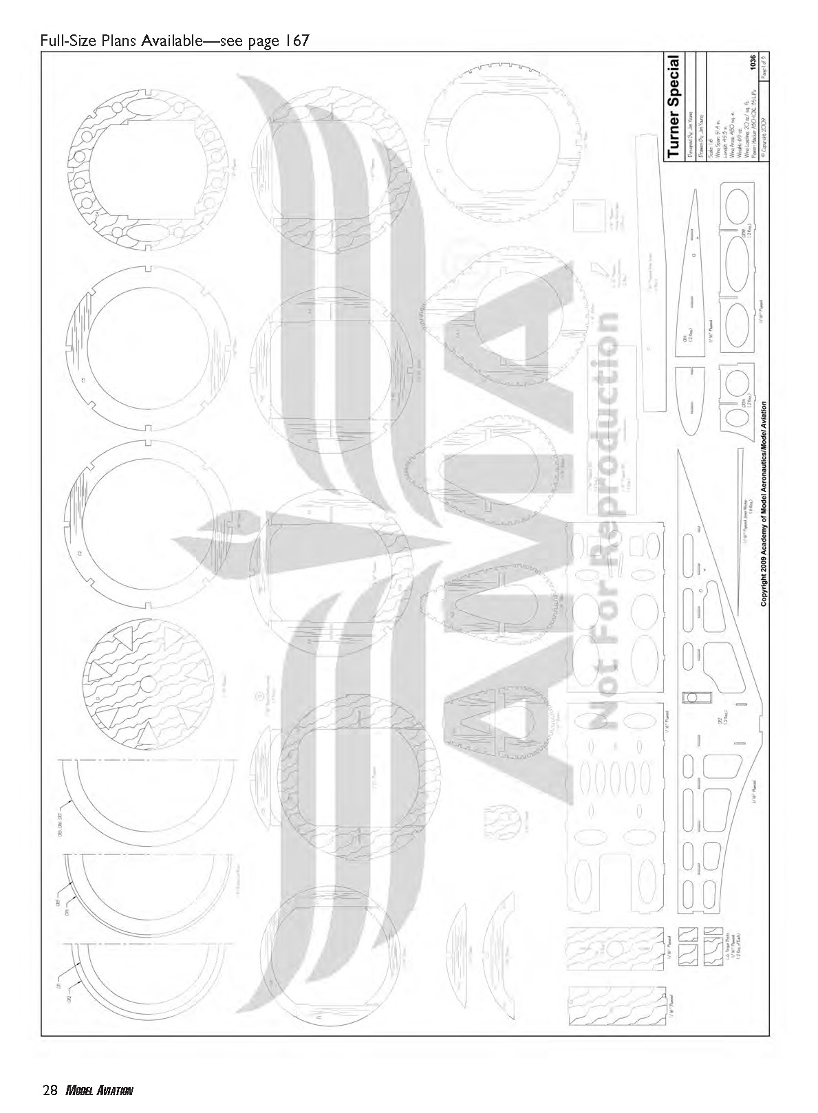
Full-size plans available — see page 167.
In 1936, feeling that his Wedell-Williams racer could not get any faster, Roscoe set out to build a new, all-out racing machine. He entered a contract with Larry Brown (of Miss Los Angeles fame) to build a racer around the new twin-row Wasp engine.
After almost two years and several modifications, Matty Laird finally completed the aircraft. He had it registered as the LTR-14 (Laird Turner Racer), much to Roscoe’s disappointment. However, after sorting out the bugs, Roscoe went on to win the 1938 and 1939 Thompson Trophy races piloting his “Turner Special.”
CONSTRUCTION
This project requires modeling experience and skill. To ease construction, I have made a short kit of laser-cut parts, foam wing cores, and vacuum-formed canopy available from me. If you take on fabricating those parts yourself, cutting your own “kit” now will speed construction.
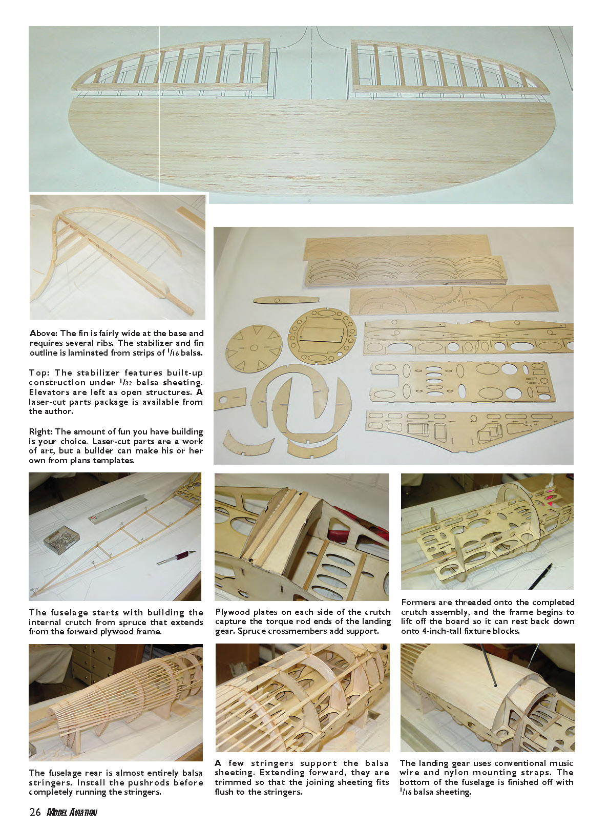
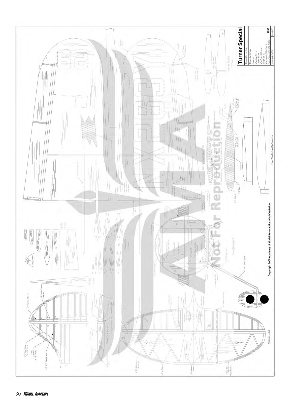
Tail Feathers
The stabilizer/elevator and fin/rudder outlines are laminated from four layers of 1/16-inch balsa. You can either cut a cardboard template or use several pins through the plans to form the outlines. I used aliphatic glue and wet the strips to make them easier to bend.
- Pin the stabilizer/elevator outline over the plans, and cut and glue in place the internal structure.
- The stabilizer is covered top and bottom with 1/32-inch balsa sheeting; the elevators are left as open structures.
- Laminate the tail filler piece from 1/16-inch balsa. Sand a slot in the front of this piece to clear the elevator joiner wire.
- Cut a 1/4-inch square balsa stick for the rudder leading edge (LE), and glue the rudder ribs to it. Fit the laminated rudder outline to the ribs and glue in place. Add balsa blocks to support Robart hinge points.
- Wrap the rudder LE with 1/16-inch balsa or two layers of 1/32-inch balsa. Wet the balsa first and pin or tape it in place while it dries before gluing. Add balsa capstrips to the ribs. The rudder is wide enough at the base to accommodate pull-pull control, or install a control linkage of your choice.
- Glue fin ribs F1 through F7 to the 1/4-inch balsa fin post F8 and the laminated fin outline. Temporarily hinge the rudder, and cut some 1/4-inch balsa triangle stock to fit on each side of the rudder to hide the hinge line. Set these aside to be glued in when the fin is installed on the fuselage.
Wings
The wing has a foam core and is sheeted with 1/16-inch balsa. A laminated plywood wing joiner is built into each wing panel. Laminate the two wing joiners from three layers of 1/16-inch plywood and sand the top and bottom edges smooth.
- Prepare the cores for sheeting by beveling the root end 3°. Cut the cores to accept the wing joiners. Glue the wing joiner, root ribs, and subribs to the cores. Glue the wingtip core to the root assembly.
- Cut slots for the aileron extensions and lay them in place. Protect them at the root rib with heat-shrink tubing or electrical tape.
- Sheet the wing with 1/16-inch balsa using your favorite method. I recommend epoxy or Gorilla Glue and the vacuum-bag technique.
- Cut the ailerons and flaps free from the wing. Face the wing LE and trailing edge (TE) with 1/4-inch balsa. Similarly, face the LE of the ailerons and flaps. True the ends of the ailerons and the tip end of the flaps, and face them with 1/16-inch balsa.
- The root ends of the flaps have a pocket built into them to receive the control rod. Remove approximately half of the foam core from the root end of the flap.
- The inside of the bottom skin is reinforced with 1/64-inch plywood. Use a 1/16-inch shim and fill the remaining space above it with balsa block. Sand a bevel (roughly 1/8 inch) along the lower LE of the flaps. Hinge the flaps to the wing along this line.
- Cut balsa block for the wingtips and glue them in place. I reinforced the TE of the wingtips by cutting a slot with a razor saw and gluing in a small piece of 1/64-inch plywood. Sand everything away that doesn't look like a wingtip.
- Cut an opening for the aileron servos and make hatches from 1/16-inch plywood.
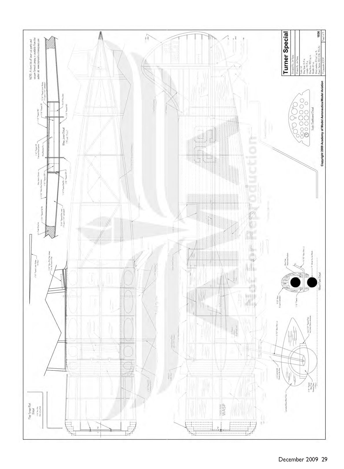
Fuselage
The fuselage is framed up over an internal crutch; 1/4-inch x 1/4-inch spruce longerons are glued to the crutch sides. Fit the radio tray CR1s and spar box pieces SB1s and SB2 to the sides. Position the crutch assembly over the plans and pin it in place before gluing.
- Cut the longerons to length, taper the ends, and glue them together. Cut and glue the balsa crossbraces and diagonal braces between the longerons.
- Laminate the plywood landing gear mounts and two 1/8-inch x 1/4-inch spruce sticks together. Glue F2A and F3A in place between the crutch sides.
- Laminate the 1/16-inch plywood torque blocks and epoxy them in place on the inside of the crutch sides. Epoxy the landing gear mount in place.
- Remove the assembly from the board. Glue the remaining crutch pieces in place, using the fuselage formers to align them. Glue the fuselage formers and motor mount in place. Add triangle-stock reinforcements to all motor-mount joints.
- Bend the flap torque rods from 1/16-inch-diameter music wire, using inner Nylrods for a bearing. Insert the torque rods into the holes in the crutch sides, and glue the wing-root plates CR4s in place. Glue the torque-rod sleeve in place and brace them near the slots in the radio tray.
- Cut three fixture blocks from 4-inch-wide, 1/2-inch balsa, and fixture the fuselage over the plans. Bend the landing gear from 5/32-inch-diameter music wire and secure in place with a pair of nylon straps and screws.
- Glue the balsa diagonal braces from F7 to F10. Start installing the 3/32-inch x 3/16-inch balsa rear stringers. Each stringer is notched to half its depth at F7 and F11 and extends at least 1 inch past these formers.
- Glue three 1/4-inch square balsa stringers into the notches from F2 to F7. Add scrap balsa to the inside edges of the CR4s to aid in gluing the fuselage sheeting.
- The fuselage has a gentle compound curve, but you should attain good results with four 3-inch-wide pieces of 1/16-inch balsa. The fuselage should now be stable enough to be removed from the fixtures.
- Finish installing the upper rear stringers. The edges of the cockpit are framed with scrap balsa.
- A large access hatch is built into the top of the fuselage. Cut four pieces of 1/16-inch basswood for the hatch edges; they should be oversized in width. Glue the bottom piece and F6 into the fuselage structure.
- Use waxed paper and set the top piece in place, and glue the hatch formers in place. Leave a 1/32-inch gap between the hatch end formers and the fuselage formers.
- Sheet the hatch and fuselage with 1/16-inch balsa. The sheeting should be beveled to fit tight to the basswood pieces. As you install the sheeting, cut it between F2A and F2B and F6 and F6A. Cut the hatch free from the fuselage.
- Face the front and rear end of the hatch and hatch opening with 1/64-inch plywood. Put the hatch back in place and sand the basswood and plywood to match the sheeting. Cut the sheeting aft of F7 to shape for the cockpit, and trim the canopy to fit.
- Laminate the 1/4-inch balsa SC1 through SC7. Glue the subcowl to the front of F2. Glue the F1 pieces in place and sand the subcowl to shape.
- Position the cowl formers on the front of the fuselage crutch. The cowl is held in place with two screws that go through C1 into the firewall.
- Cut 1/4-inch square balsa stringers and glue them in place around the formers. Sheet the cowl with 1/16-inch balsa. The sheeting extends 1/4 inch behind C4, and a strip of 1/64-inch plywood reinforces it. The front of the cowl is laminated from seven rings of 1/4-inch balsa and sanded to shape.
- Laminate two wing-joiner wedges from three layers of 1/16-inch plywood. With the wing joiner protected with waxed paper, slide one wing into place and push a wedge in from the opposite side. The wedges hold the wing joiner against the bottom of the spar box and distribute the flight loads to the fuselage crutch.
- Make adjustments and glue the wedge to the inside top of the spar box. Repeat for the other wing and wedge.
- Slide the wings in place and check the fit to the CR4s; use them to line up the stabilizer before gluing it in place. Glue the top of F11 to the stabilizer. Adhere the tail-filler piece in place. Glue the fin assembly in place.
- Temporarily hinge the rudder and use balsa to fill the gap between it and the tail-filler piece. Install the rudder control before sheeting the sides of the fin and adding capstrips.
- The bottom rear of the fuselage is sheeted with 1/16-inch balsa. Glue F12 in place and adhere the 1/4-inch square spruce tail skid to it. Add the 1/4-inch balsa skids, and reinforce them with 1/64-inch plywood on each side.
- The landing gear is finished with balsa filler sandwiched between 1/16-inch balsa sheeting. Sand the landing gear to an airfoil shape. Use balsa or filler to create the fillets around the landing gear. The fillet should be glued only to the fuselage — not to the landing gear — so it can flex.
- The wheel pants are laminated and carved from balsa. The 1/16-inch plywood plates provide a mounting point for wheel-pant hardware.
Final Assembly
- Fit the wings to the fuselage, and use a pin or machine screw through the hole in the spar box and spars to secure them in place.
- Use either balsa triangle stock or your favorite filler to create the small wing fillet.
- The original LTR-14 was painted silver, and most iron-on coverings offer a close match. The fuselage rear is quite curvy, so expect to use three or four pieces of covering around it to get all the wrinkles out.
- Self-adhesive vinyl graphics are available from Callie Graphics. The Turner Special had several sponsors during its racing career and appeared as the "Pesco Special" and "Ring Free Meteor."
- I have created the markings for the "Miss Champion," and the BMP files are available on my Web site — T&J Models — for download. I printed the images on water-slide decal sheets.
- It has been said that scale models are never finished; you just stop working on them. How far you go with the cooling scoops, cockpit, pilot, and engine detail is up to you. When painting the pilot, you might want to keep in mind that I've seen color film of Roscoe Turner wearing a white leather helmet.
- Complete your radio installation at this time. I use Hitec HS-55 servos for the ailerons, HS-65s for the rudder and elevator, and DS821s for the flaps. All servos are hooked up to a Spektrum AR7000 receiver.
The power system I am using is providing great results. It consists of:
- Hacker A30-10XL motor
- APC 14 x 7E propeller
- Skyshark R/C 5000 mAh 3S Li-Poly battery
- FMA Direct BalancePro Discharge Protection Module
- Castle Creations Phoenix-45 ESC and Ultimate BEC
This setup draws approximately 36 amps static and provides more than enough power.
Note: If you are using flaps, you will need to use a separate receiver battery or a switching BEC, because few ESCs can supply enough current for five servos. The battery capacity might seem like overkill, but the LTR-14 has a short nose moment, so I did need the weight up front to balance it.
Flying
The Turner Special is an honest airplane. The rudder is extremely effective, and takeoffs from grass fields are no problem, even without a steerable tail wheel.
- Taxiing on grass takes only a bit of throttle management to move the tail around.
- With the recommended power system, the Turner Special can take off from a three-point stance and climbs out with authority.
- For landings, set up your normal approach and keep on a bit of power until the model is over the field. Let the airplane settle in and keep adding up-elevator, and it will give you a pretty three-wheel landing. Remember to save some power to taxi the LTR-14 back to the pits.
People might think that all racers can do is go fast and turn left. I'm happy to report that this is not the case with the Turner Special. This model is well behaved in the air and has no bad stall tendencies. It will perform any basic aerobatic maneuver (loop, stall turn, point roll, Cuban 8, etc.). With the balance point directly on the joiner tube, the LTR-14 flies inverted hands-off. The large fuselage also makes extended knife-edge flight possible.
I'd like to thank Keith Shaw for letting me pick his brain along the way and for his talented thumbs for the initial flights.
Jim Young [email protected]
Sources
- Manzano Laser Works
(505) 286-2640 www.manzanolaser.com
- Callie Graphics
(505) 281-9310 www.callie-graphics.com
- T&J Models
(505) 286-2640 www.tnjmodels.rchomepage.com
- Hacker Brushless
(480) 726-7519 www.hackerbrushless.com
- APC Propellers
(530) 661-0399 www.apcprop.com
- Skyshark R/C Corporation
(928) 854-6100 www.skysharkrc.com
- FMA Direct
(800) 343-2934 www.fmadirect.com
- Castle Creations
(913) 390-6939 www.castlecreations.com
- Spektrum RC
(800) 338-4639 www.spektrumrc.com
- Hitec RCD
(858) 748-6948 www.hitecrcd.com
Contact: Jim Young (810) 231-1684 9356 Wendover Ct. Brighton, MI 48116
Transcribed from original scans by AI. Minor OCR errors may remain.

