
Reading plans
by Paul Kohlmann
One of the best parts of writing this series of articles has been discussing modeling with some notable builders in our hobby. Pat Tritle is one of these people, and when I asked what topics he would like to see covered for new builders, his reply was immediate. He suggested a piece on how to read plans. This led to some interesting discussions about how often problems with a build can be avoided by closely reviewing the plans before the building starts. It is often useful to study all of the notes and views and then "prebuild" the project in your mind.
This article will cover the basics of how to read a technical drawing. It will focus on the correct methods that drafters normally use in industry, but it is important to recognize that model designers often work to a much looser standard.
Title Block and Notes
This should be a builder's first stop. Adding notes to a drawing can be time consuming. With that in mind, you won't find many notes on plans that the designer didn't think would be important to you.
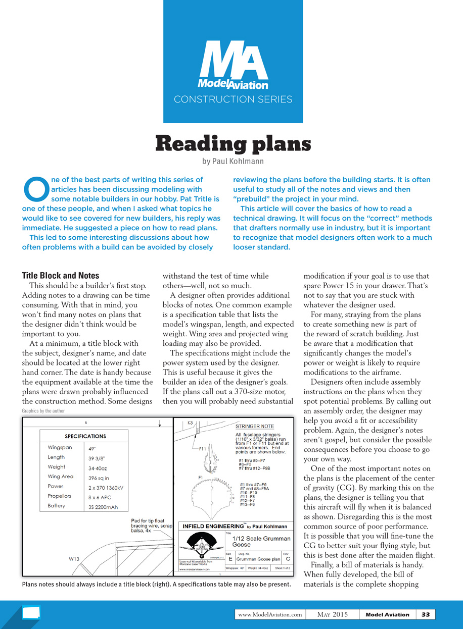
At a minimum, a title block with the subject, designer's name, and date should be located at the lower-right-hand corner. The date is handy because the equipment available at the time the plans were drawn probably influenced the construction method. Some designs withstand the test of time while others—not so much.
A designer often provides additional blocks of notes. One common example is a specification table that lists the model's wingspan, length, and expected weight. Wing area and projected wing loading may also be provided.
The specifications might include the power system used by the designer. This is useful because it gives the builder an idea of the designer's goals. If the plans call out a 370-size motor, then you will probably need substantial modification if your goal is to use that spare Power 15 in your drawer.
That's not to say that you are stuck with whatever the designer used. For many, straying from the plans to create something new is part of the reward of scratch building. Just be aware that a modification that significantly changes the model's power or weight is likely to require modification to the airframe itself.
Designers often include assembly instructions on the plans when they spot potential problems. By calling out an assembly order, the designer may help you avoid a fit or accessibility problem. Again, the designer's notes aren't gospel, but consider the possible consequences before you choose to go your own way.
One of the most important notes on the plans is the placement of the center of gravity (CG). By marking this on the plans, the designer is telling you that this aircraft will fly when it is balanced as shown. Disregarding this is the most common source of poor performance. It is possible that you will fine-tune the CG to better suit your flying style, but this is best done after the maiden flight.
Finally, a bill of materials (BOM) is handy. When fully developed, the BOM is the complete shopping list for wood, electronics, hardware, and power systems for your project. The BOM is often partial because designers understand that builders normally use the hardware and electronics that they are familiar with.
Drawing Views
Drafters have traditionally used the "glass box" to characterize the standard views on their drawings. These standard views are arranged in a specific order so that fabricators can rapidly construct a 3-D mental image of the subject. Adhering to these rules avoids problems such as building the mirror image of the intended part. Engineering drawings of this type are commonly called three-views, although more or fewer views can be incorporated.
The basic three-view layout will show the front view, the top view, and whichever side presents more detail. Model plans often use a looser standard. The main reason for the departure is that the views most needed by builders are the ones that they will be building directly on top of. A side view of the fuselage is much more useful to a builder than a strictly orthogonal arrangement because it shows the construction details that matter during assembly.
Transcribed from original scans by AI. Minor OCR errors may remain.

