
Martin MO-1
Continued from page 82
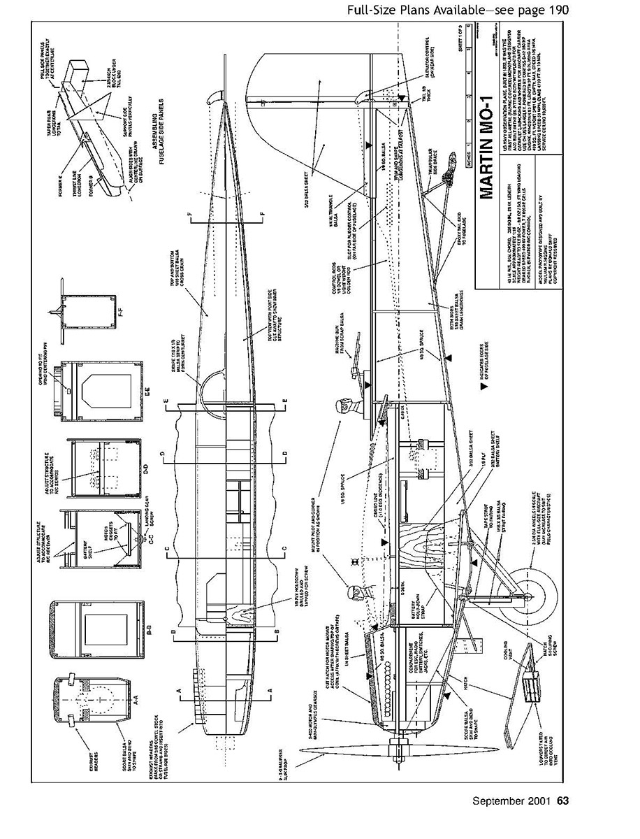
After checking to make sure all internal parts are in place, glue the bottom in position and sand the edges flush with the sides. Hold the fuselage top-rear piece until later, to make assembly of the control rods easier.
The fuselage should be strong and square at this point.
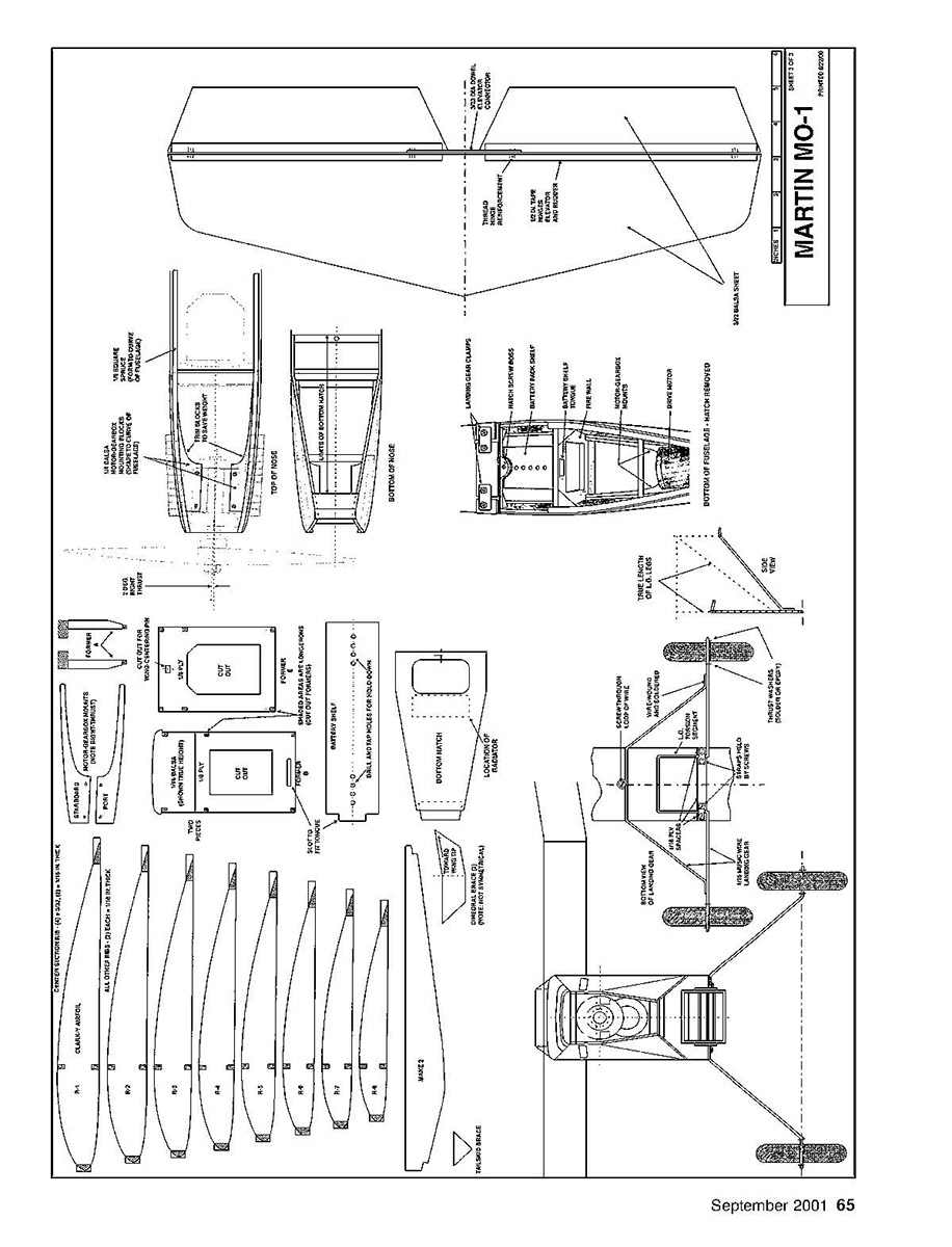
Fabricate the bottom hatch and the radiator. (Note the deflector vanes inside the radiator that direct cooling air into the opening and around the battery pack.) The hatch allows access to the space behind the motor for the Electronic Speed Control (ESC), switches, and jacks.
Wing Leading-Edge Hold-down Assembly
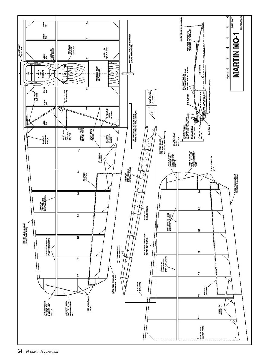
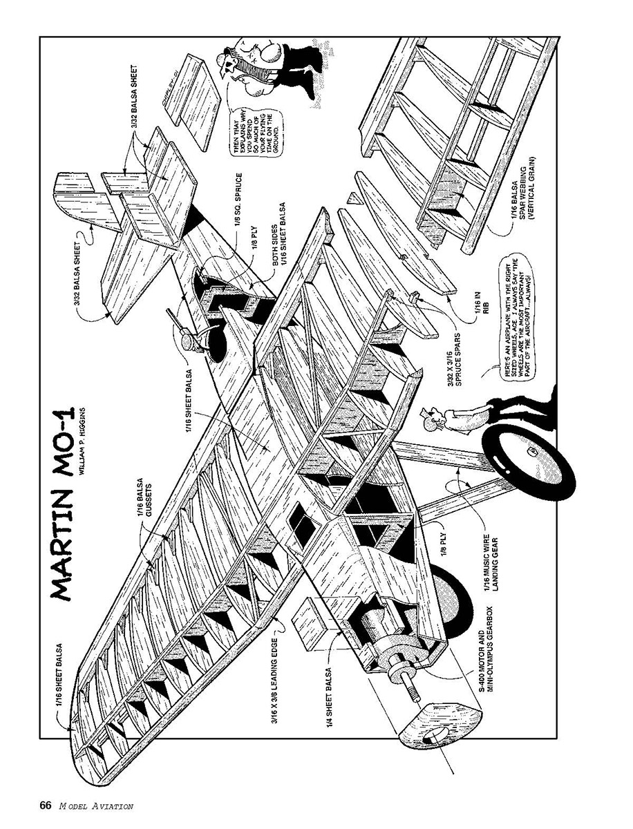
- Construct the wing center section on the plan. Do not add the sheet balsa between the center two ribs ahead of the spar yet. Check the fit of the section with the wing cutout in the fuselage.
- Cut a 1/32 plywood strip and a 1/8 x 1/2 balsa backing strip to fit accurately between the center two ribs and against the leading edge. Glue carefully in place. (These joints keep the wings and fuselage together in flight.) Shape the backing strip and the leading edge to fit the ribs.
- Cut 1/4 x 1/2 x 1/8 balsa pieces, and glue to the insides of the center two ribs, as shown on the detailed view. They should be 1/16 inch below the tops of the ribs at the rear end, and should rest on the leading edge in front.
- Cut the front surface of the assembly from 1/16 sheet balsa. Glue the top sheet in place, then add the 3/8 x 3/8 balsa cockpit front piece. Sand the assembly to match the shape of the fuselage cowl.
The wing hold-down screw hole should be drilled and tapped after the wing and fuselage are finished.
Wing
- Construct the outboard wing sections on the plan.
- Note that the rib at the inboard end is part of the center section, and the 1/8 square hard-balsa diagonal braces are added when the wing is assembled.
- Assemble the three sections, using 2x high supports at the wingtips to determine dihedral.
- The 1/8 plywood dihedral braces are glued to the rear of the spar webbing, between the top and bottom spar. Note that the dihedral braces are not symmetrical; the thicker end fits in the center section.
- Add the 1/8 square hard-balsa diagonal braces as shown, and glue bamboo cocktail sticks at the leading edge and near the trailing edge through holes in the joining ribs. Use epoxy on these joints, since CyA does not work well into bamboo. These strengthen the wing joint without adding much weight. Add gussets as shown.
- Epoxy the hardwood wing-centering pin to the top of the trailing edge, exactly at the center point.
- Check the wing's fit in the fuselage before covering it.
Landing Gear
The landing gear is of typical construction, except for the added torsion segment in the front leg and loop in the wire at the center of the rear legs.
Bill turned the lightweight wheels in a hand drill from blue Styrofoam that had been mounted on small wooden spools. Discs of 1/8 plywood provide side-supporting "hubcaps." His wheels weigh roughly eight grams apiece.
Equipment
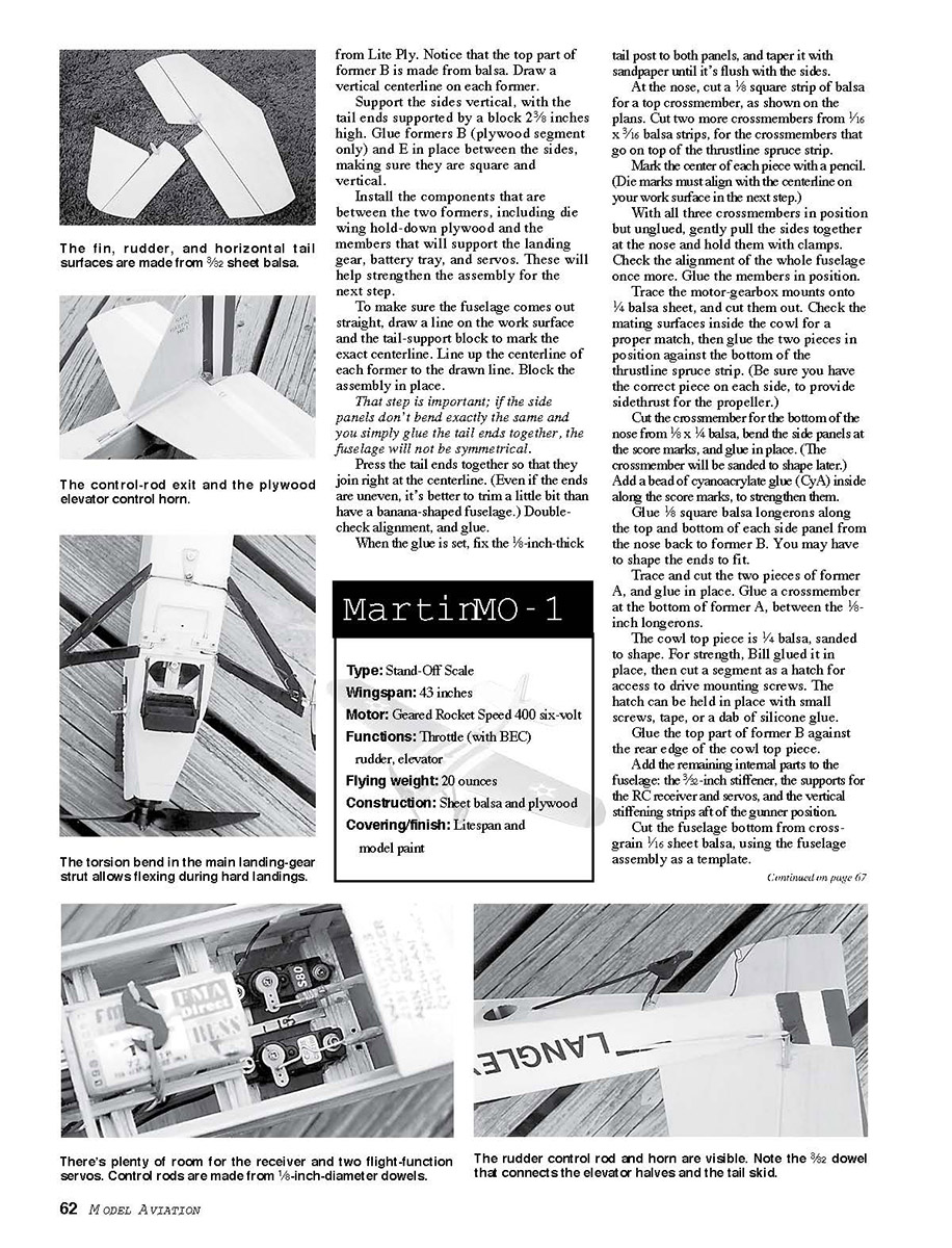
Bill used an Olympus 2.3:1 gearbox on the Rocket 400 motor, a 9 x 5 Graupner Slim prop, a Sprite ESC with Battery Eliminator Circuit (BEC), and seven 600-mAh Ni-Cd cells for power.
The battery tray is drilled and tapped along its length, so the battery pack can be strapped down where necessary for center-of-gravity (CG) adjustment (see instructions for taping the wing hold-down).
Mini-size servos were used, and 1/8-inch diameter doweling was used for the control rods. Bill made control horns from 1/32 plywood.
Control surface hinges are Mylar hinge tape, reinforced at the ends with a few figure-8 loops of thread stitching.
Finishing
- The top of the fuselage aft of the wing is glued on after the servos and control rods are installed.
- The gun turret is shaped from 1/8 x 1/8 balsa strip.
- The wing is held down by two nylon screws. With the wing held in position on the fuselage, drill a pilot hole through the cockpit and the plywood piece in the fuselage. Remove the wing, and enlarge the hole in the cockpit. Apply thin CyA to the inside of both holes to harden them.
- Wait several hours—even overnight—then carefully tap the hole in the plywood. Waiting that long allows the glue to harden and yields cleaner threads.
- Shape the fairing pieces on top of the wing to match the fuselage.
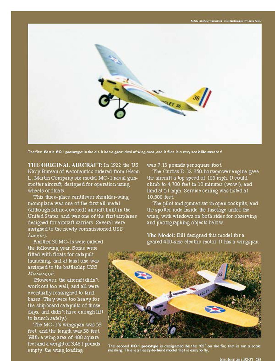
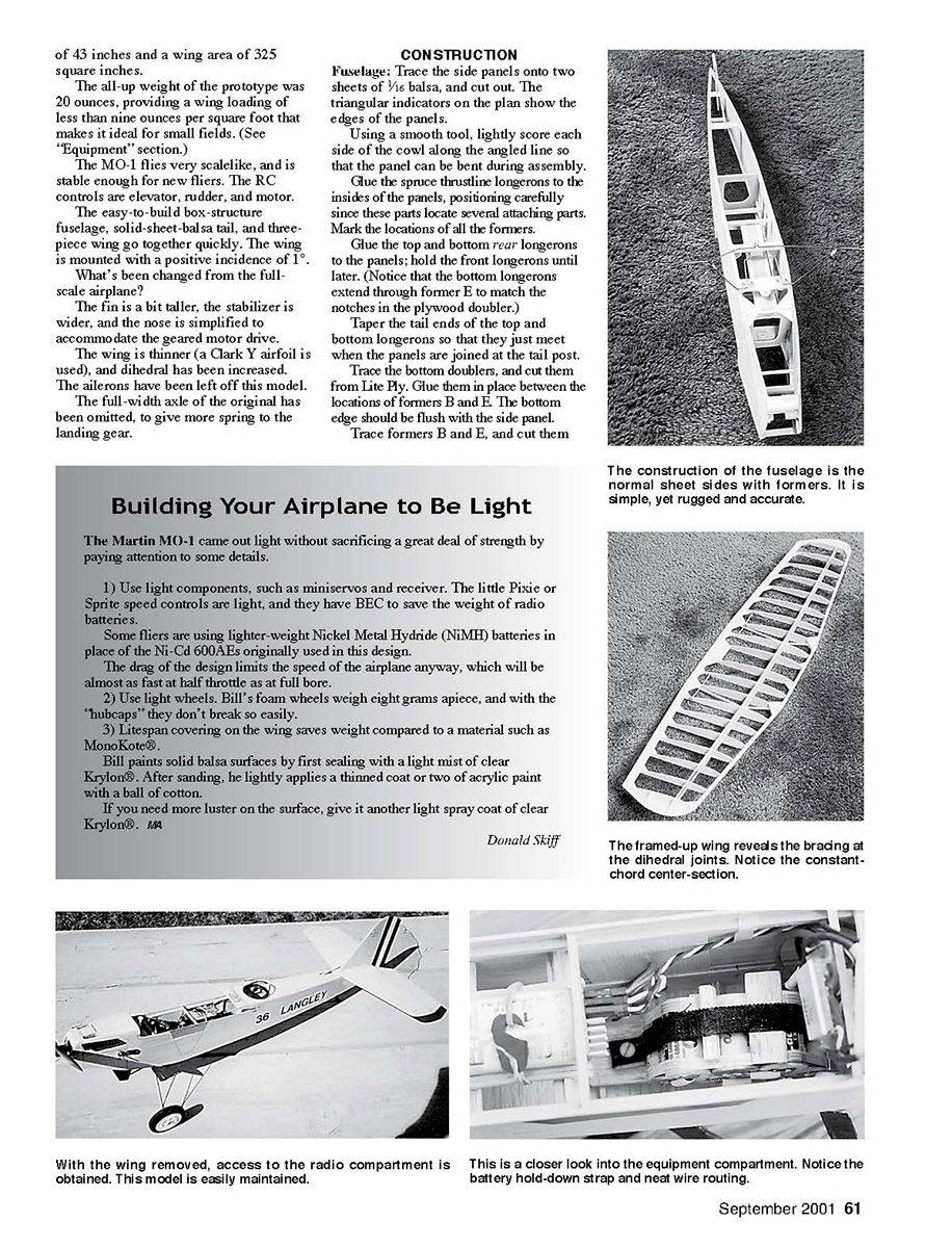
On the second prototype, the wing was covered with yellow LiteSpan and the fuselage and tail were painted gray, except for the elevator surfaces, which were yellow, and the rudder, which carries the vertical red, white, and blue stripes. The undercarriage was painted black.
Flying
- The CG should be right at the spar location.
- With its light wing loading, this model is a well-behaved and gentle flier. It takes off easily from short grass, but don't expect 45° climbs until it gets up to cruising speed.
- Bill typically clocked eight or nine minutes of flight by keeping an eye on trim levels, flying weight, and motor condition.
Acknowledgements
This project couldn't have been completed without the help of the Ann Arbor Falcons members. Their accumulated years of experience and expertise helped us get a flyable airplane, and their encouragement kept our enthusiasm up through the months of design and flight trials.
Transcribed from original scans by AI. Minor OCR errors may remain.

