
Maxford USA Bristol Fighter F.2B ARF
Fly your own reconnaissance missions with the Brisfit
Maxford USA has a reputation for manufacturing high-quality ARF aircraft. The company also produces some seldom-modeled aircraft such as the German World War I fighter Hansa-Brandenburg W.29.
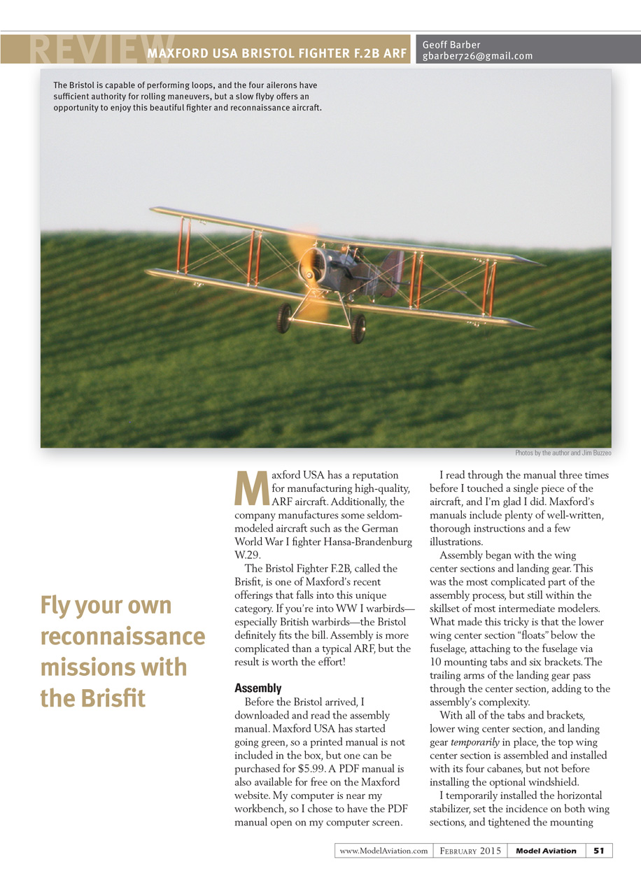
The Bristol Fighter F.2B, called the Brisfit, is one of Maxford’s recent offerings that falls into this unique category. If you’re into WW I warbirds—especially British warbirds—the Bristol definitely fits the bill. Assembly is more complicated than a typical ARF, but the result is worth the effort.
Assembly
Before the Bristol arrived, I downloaded and read the assembly manual. Maxford USA has started going green, so a printed manual is not included in the box, but one can be purchased for $5.99. A PDF manual is also available for free on the Maxford website. My computer is near my workbench, so I chose to have the PDF manual open on my computer screen.
I read through the manual three times before I touched a single piece of the aircraft, and I’m glad I did. Maxford’s manuals include plenty of well-written, thorough instructions and a few illustrations.
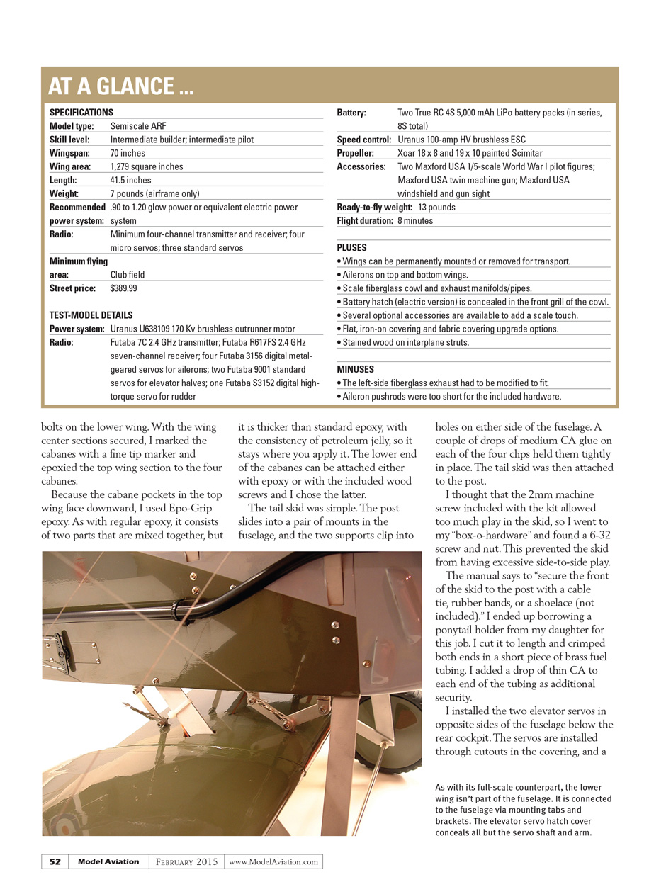
Assembly began with the wing center sections and landing gear. This was the most complicated part of the assembly process, but still within the skillset of most intermediate modelers. What made this tricky is that the lower wing center section “floats” below the fuselage, attaching to the fuselage via 10 mounting tabs and six brackets. The trailing arms of the landing gear pass through the center section, adding to the assembly’s complexity.
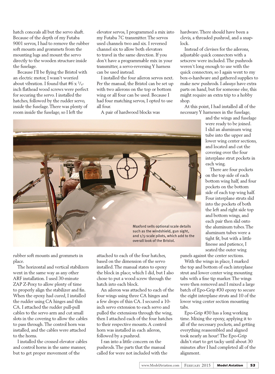
With all of the tabs and brackets, lower wing center section, and landing gear temporarily in place, the top wing center section was assembled and installed with its four cabanes, but not before installing the optional windshield. I temporarily installed the horizontal stabilizer, set the incidence on both wing sections, and tightened the mounting bolts on the lower wing. With the wing center sections secured, I marked the cabanes with a fine-tip marker and epoxied the top wing section to the four cabanes.
Because the cabane pockets in the top wing face downward, I used Epo-Grip epoxy. As with regular epoxy, it consists of two parts that are mixed together, but it is thicker than standard epoxy, with the consistency of petroleum jelly, so it stays where you apply it. The lower end of the cabanes can be attached either with epoxy or with the included wood screws; I chose the latter.
The tail skid was simple. The post slides into a pair of mounts in the fuselage, and the two supports clip into holes on either side of the fuselage. A couple of drops of medium CA glue on each of the four clips held them tightly in place. The tail skid was then attached to the post.
I thought that the 2 mm machine screw included with the kit allowed too much play in the skid, so I went to my “box-o-hardware” and found a 6-32 screw and nut. This prevented the skid from having excessive side-to-side play.
The manual says to “secure the front of the skid to the post with a cable tie, rubber bands, or a shoelace (not included).” I ended up borrowing a ponytail holder from my daughter for this job. I cut it to length and crimped both ends in a short piece of brass fuel tubing. I added a drop of thin CA to each end of the tubing as additional security.
I installed the two elevator servos in opposite sides of the fuselage below the rear cockpit. The servos are installed through cutouts in the covering, and a hatch conceals all but the servo shaft. Because of the depth of my Futaba 9001 servos, I had to remove the rubber soft mounts and grommets from the mounting lugs and mount the servo directly to the wooden structure inside the fuselage.
Because I planned to fly the Bristol with an electric motor, I wasn’t worried about vibration. I found that #6 x 3/4-inch flathead wood screws were perfect for securing the servos. I installed the hatches, followed by the rudder servo, inside the fuselage. There was plenty of room inside the fuselage, so I left the rubber soft mounts and grommets in place.
The horizontal and vertical stabilizers went in the same way as any other ARF installation. I used 30-minute ZAP Z-Poxy to allow plenty of time to properly align the stabilizer and fin. When the epoxy had cured, I installed the rudder using CA hinges and thin CA. I attached the rudder pull-pull cables to the servo arm and cut small slots in the covering to allow the cables to pass through. The control horn was installed, and the cables were attached to the horns.
I installed the crossed elevator cables and control horns in the same manner, but to get proper movement of the elevator servos, I programmed a mix into my Futaba 7C transmitter. The servos used channels two and six. I reversed channel six to allow both elevators to travel in the same direction. If you don’t have a programmable mix in your transmitter, a servo-reversing Y harness can be used instead.
I installed the four aileron servos next. Per the manual, the Bristol can be set up with two ailerons on the top or bottom wing or all four can be used. Because I had four matching servos, I opted to use all four.
A pair of hardwood blocks was attached to each of the four hatches, based on the dimensions of the servos installed. The manual states to epoxy the block in place, which I did, but I also chose to put a wood screw through the hatch into each block.
An aileron was attached to each of the four wings using three CA hinges and a few drops of thin CA. I secured a 10-inch servo extension to each servo and pulled the extensions through the wing, then I attached each of the four hatches to their respective mounts. A control horn was installed in each aileron, followed by a pushrod.
I ran into a little concern on the pushrods. The parts that the manual called for were not included with the hardware. There should have been a clevis, a threaded pushrod, and a snap-lock. Instead of clevises for the ailerons, adjustable quick connectors with a setscrew were included. The pushrods weren’t long enough to use with the quick connectors, so I again went to my box-o-hardware and gathered supplies to make new pushrods. I always have extra parts on hand, but for someone else, this might require an extra trip to a hobby shop.
At this point, I had installed all of the necessary Y harnesses in the fuselage, and the wings and fuselage were ready to be joined. I slid an aluminum wing tube into the upper and lower wing center sections, and located and cut the covering over the four interplane strut pockets in each wing.
There are four pockets on the top side of each bottom wing half, and four pockets on the bottom side of each top wing half. Four interplane struts slid into the pockets of both the left and right side top and bottom wings, and each pair then slid onto the aluminum tubes. The aluminum tubes were a tight fit, but with a little finesse and patience, I seated the outer wing panels against the center sections.
With the wings in place, I marked the top and bottom of each interplane strut and lower center wing mounting tabs with a fine-tip marker. The wings were then removed and I mixed a large batch of Epo-Grip #30 epoxy to secure the eight interplane struts and 10 of the lower wing center section mounting tabs.
Epo-Grip #30 has a long working time. Mixing the epoxy, applying it to all of the necessary pockets, and getting everything reassembled and aligned took nearly an hour. The Epo-Grip didn’t start to get tacky until about 30 minutes after I had completed all of the alignment.
It was time to work on the business end of the airplane. Because I used the recommended electric setup, the manual was easy to follow. If you plan to install a different motor, be ready to read and reread the manual because it can be slightly vague.
I mounted the motor to the motor box according to the manual, slid the box into the fuselage, and installed the cowl. At this point, I was able to adjust the depth of the motor box and mark its proper location. The manual describes two ways to mount the motor box: permanently with epoxy or with a metal L-channel and screws (for future repairs).
I chose the latter, but instead used several screws around the motor box and replaced the cabane screws with longer ones to secure the motor box. The motor box wasn't going anywhere, and it was still removable.
I soldered the battery and motor connection to the Uranus 100-amp ESC, and installed it in the bottom of the motor box. The wiring was secured and ready to use.
My friend, Dan Naumowicz, provided me two 4S 5,000 mAh LiPo batteries for this review. Dan is the president and owner of TrueRC. He is able to manufacture custom LiPo packs to fit nearly any shape or size project, and he's a nice guy, too.
The batteries were slightly large for the battery tray, so I made room according to the instructions for using an optional 10S battery. There is plenty of room for large batteries if you trim the ribs in the battery tray.
The Uranus 100-amp ESC does not have a BEC, so I installed a 6.0-volt 1,400 mAh NiMH battery and power switch for the receiver. There is a cutout in the forward cockpit for the switch that is the perfect size for a charging jack/switch combination. I secured the receiver and receiver battery in front of the rudder servo, and connected all of the servo wires and extensions to the Futaba R617FS 2.4 GHz receiver.
After making sure the motor was spinning in the correct direction, I got the cowl ready for the final installation. This required installing the exhaust tube mounts to the sides of the fuselage and attaching the exhaust tubes to the cowl. I mounted the cowl first and fit the exhaust tubes to the cowl and fuselage. The left-side exhaust tube would not fit correctly.
I had to cut the tube behind the header and rotate the long section approximately 15° to get both parts to work. To reassemble the tube, I glued a scrap piece of balsa inside the tubes.
When the CA had cured, I attached the tubes to their mounts with the included zip ties. Four screws were used to permanently attach the cowl to the airplane.
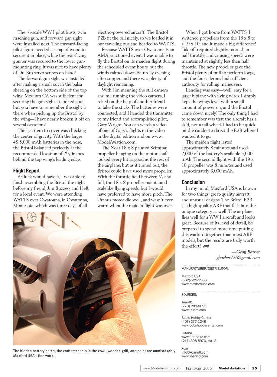
The front grill/battery hatch had to be modified slightly to fit the large Uranus motor, but my Dremel tool and a small sanding drum made short work of that.
I purchased the 18 x 8 Xoar painted Scimitar propeller from Steve Thomas, the owner of Bob's Hobby Center in Orlando, Florida. Per the motor and manual recommendations, I chose a propeller in the middle of the selection range.
I was getting close. It was time to work on the flying wires. I attached the 24 wire anchors to the cabanes and interplane struts and started rigging the wires. To my surprise, this was one of the quickest parts of the entire assembly process. It was easy following the guide in the manual. The wingtip skids and decals followed suit, and went on without a hitch, but be prepared to spend a little time getting the large roundels on the wings. They weren't difficult, just very large.
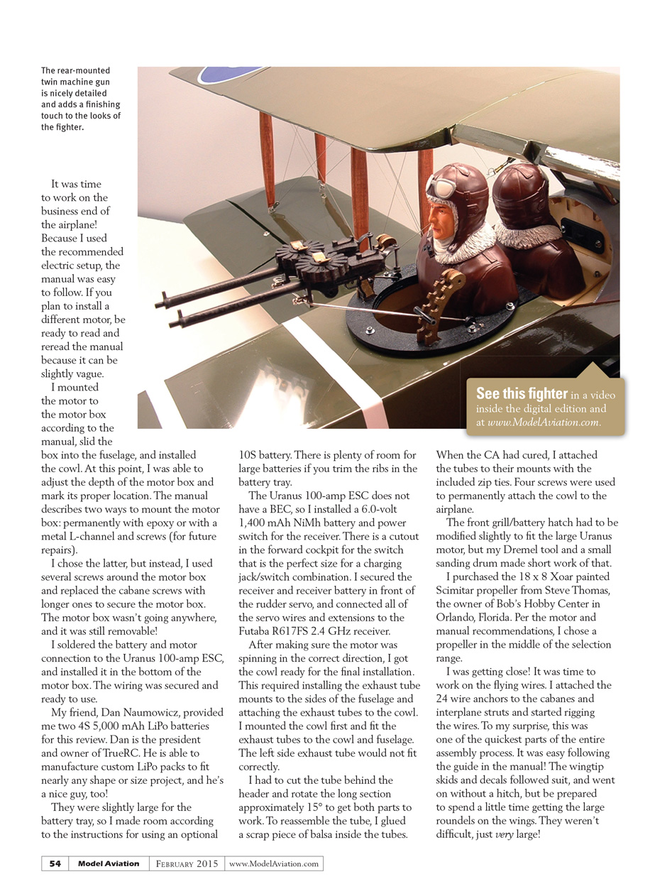
The 1/5-scale WW I pilot busts, twin machine gun, and forward gun sight were installed next. The forward-facing pilot figure needed a scrap of wood to secure it in place, while the rear-facing gunner was secured to the lower gun-mounting ring. It was nice to have plenty of Du-Bro servo screws on hand.
The forward gun sight was installed after making a small cut in the balsa sheeting on the bottom side of the top wing. Medium CA was sufficient for securing the gun sight. It looked cool, but you have to remember the sight is there when picking up the Bristol by the wing—I have nearly broken it off on several occasions.
The last item to cover was checking the center of gravity. With the larger 4S 5,000 mAh batteries in the nose, the Bristol balanced perfectly at the recommended location of 2 5/8 inches behind the top wing’s leading edge.
Flight Report
As luck would have it, I was able to finish assembling the Bristol the night before my friend, Jim Buzzeo, and I left for a local event. We were attending WATTS over Owatonna, in Owatonna, Minnesota, which was three days of all‑electric-powered aircraft. The Bristol F.2B fit the bill nicely, so we loaded it in our traveling bus and headed to WATTS.
Because WATTS over Owatonna is an AMA-sanctioned event, I was unable to fly the Bristol on its maiden flight during the scheduled event hours, but the winds calmed down Saturday evening after supper and there was plenty of daylight remaining.
With Jim manning the still camera and me running the video camera, I relied on the help of another friend to take the sticks. The batteries were connected, and I handed the transmitter to my friend and accomplished pilot, Gary Wright. You can watch a video of one of Gary’s flights in the video in the digital edition and on www.ModelAviation.com.
The Xoar 18 x 8 painted Scimitar propeller hanging on the motor shaft looked every bit as good as the rest of the airplane, but as it turned out, the Bristol could have used more propeller. With the throttle held between 3/4 and full, the 18 x 8 propeller maintained scalelike flying speeds, but I would have preferred to have more pitch. The Uranus motor did well, and wasn’t even warm when the maiden flight was over.
When I got home from WATTS, I switched propellers from the 18 x 8 to a 19 x 10, and it made a big difference. Takeoff required slightly more than half throttle, and cruising speeds were maintained at slightly less than half throttle. The new propeller gave the Bristol plenty of pull to perform loops, and the four ailerons had sufficient authority for rolling maneuvers.
Landing was easy—well, easy for a large biplane with flying wires. I simply kept the wings level with a small amount of power on, and the Bristol came down nicely. The only thing I had to remember was that the aircraft has a skid, not a tail wheel. I had to be quick on the rudder to direct the F.2B where I wanted it to go.
The maiden flight lasted approximately 8 minutes and used 2,000 mAh of the battery’s available 5,000 mAh. The second flight with the 19 x 10 propeller was 8 minutes and used approximately 3,000 mAh.
Conclusion
In my mind, Maxford USA is known for two things: great-quality aircraft and unusual designs. The Bristol F.2B is a high-quality ARF that falls into the unique category as well. The airplane flies well for a WW I aircraft and looks great. Because of its level of detail, be prepared to spend more time putting this warbird together than most ARF models, but the results are truly worth the effort.
—Geoff Barber [email protected]
Manufacturer/Distributor
- Maxford USA
- (562) 529-3988
- www.maxfordusa.com
Sources
- TrueRC
- (773) 203-8695
- www.truerc.com
- Bob’s Hobby Center
- (407) 277-1248
- www.bobshobbycenter.com
- Futaba
- www.futaba-rc.com
- (217) 398-8970, ext. 2
Transcribed from original scans by AI. Minor OCR errors may remain.

