
MAXFORD USA GOTHA G.IV
Greg Gimlick [email protected]
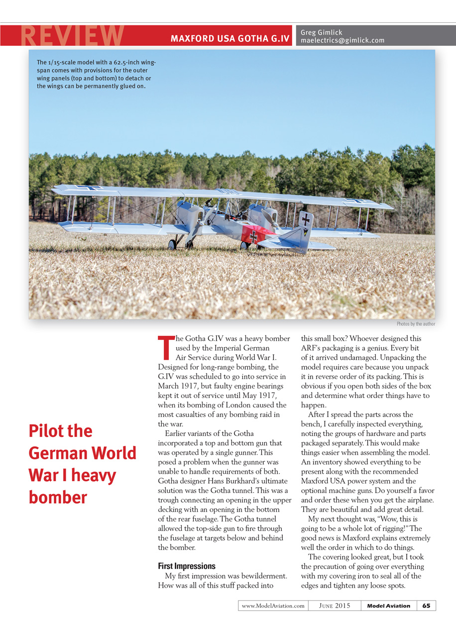
The Gotha G.IV was a heavy bomber used by the Imperial German Air Service during World War I. Designed for long-range bombing, the G.IV was scheduled to go into service in March 1917, but faulty engine bearings kept it out of service until May 1917, when its bombing of London caused the most casualties of any bombing raid in the war.
Earlier variants of the Gotha incorporated a top and bottom gun that was operated by a single gunner. This posed a problem when the gunner was unable to handle requirements of both. Gotha designer Hans Burkhard’s ultimate solution was the Gotha tunnel. This was a trough connecting an opening in the upper decking with an opening in the bottom of the rear fuselage. The Gotha tunnel allowed the top-side gun to fire through the fuselage at targets below and behind the bomber.
First Impressions
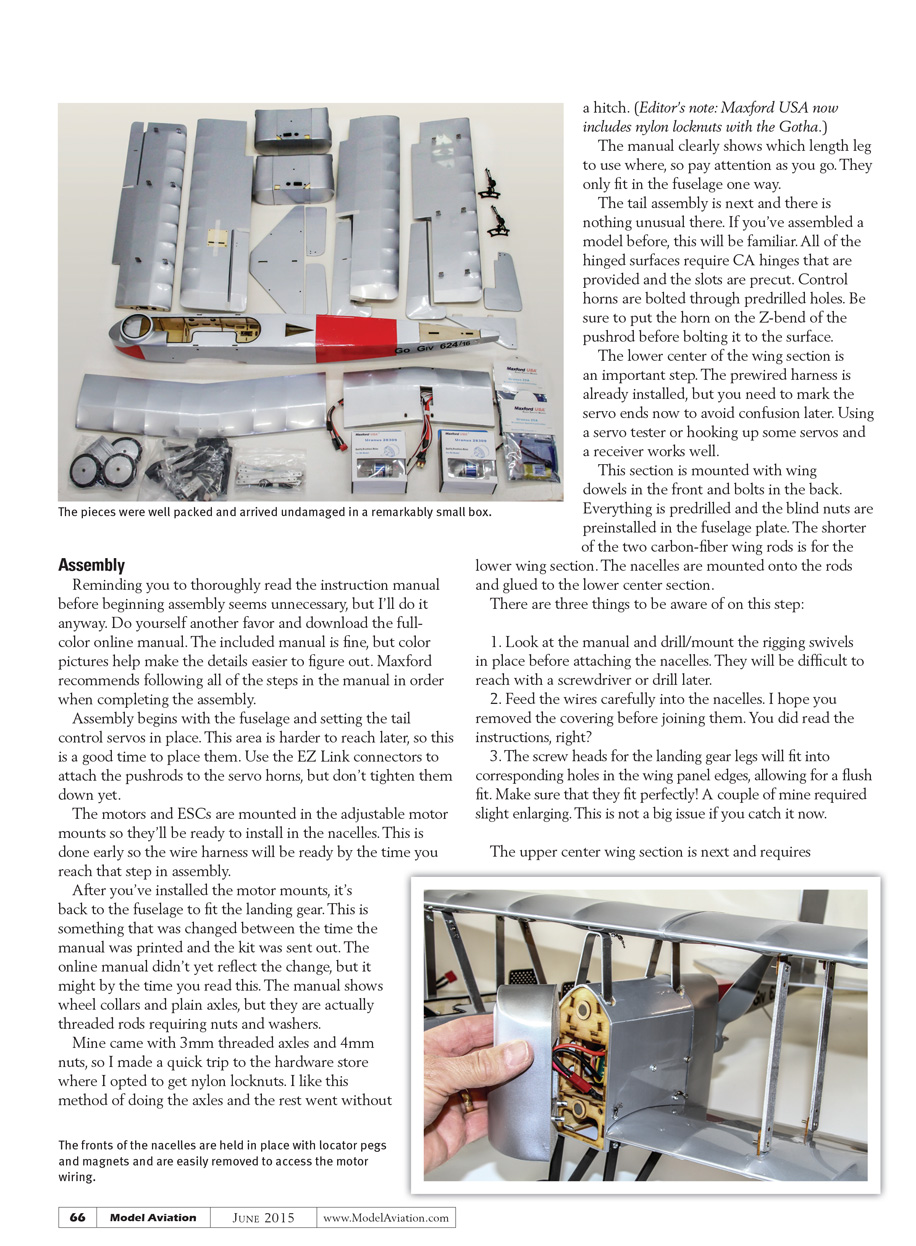
My first impression was bewilderment. How was all of this stuff packed into this small box? Whoever designed this ARF’s packaging is a genius. Every bit of it arrived undamaged. Unpacking the model requires care because you unpack it in reverse order of its packing. This is obvious if you open both sides of the box and determine what order things have to happen.
After I spread the parts across the bench, I carefully inspected everything, noting the groups of hardware and parts packaged separately. This would make things easier when assembling the model. An inventory showed everything to be present along with the recommended Maxford USA power system and the optional machine guns. Do yourself a favor and order these when you get the airplane. They are beautiful and add great detail.
My next thought was, “Wow, this is going to be a whole lot of rigging!” The good news is Maxford explains extremely well the order in which to do things.
The covering looked great, but I took the precaution of going over everything with my covering iron to seal all of the edges and tighten any loose spots.
After you’ve installed the motor mounts, it’s back to the fuselage to fit the landing gear. This is something that was changed between the time the manual was printed and the kit was sent out. The online manual didn’t yet reflect the change, but it might by the time you read this. The manual shows wheel collars and plain axles, but they are actually threaded rods requiring nuts and washers.
Mine came with 3 mm threaded axles and 4 mm nuts, so I made a quick trip to the hardware store where I opted to get nylon locknuts. I like this method of doing the axles and the rest went without a hitch. (Editor’s note: Maxford USA now includes nylon locknuts with the Gotha.)
The manual clearly shows which length leg to use where, so pay attention as you go. They only fit in the fuselage one way.
The tail assembly is next and there is nothing unusual there. If you’ve assembled a model before, this will be familiar. All of the hinged surfaces require CA hinges that are provided and the slots are precut. Control horns are bolted through predrilled holes. Be sure to put the horn on the Z-bend of the pushrod before bolting it to the surface.
The lower center of the wing section is an important step. The pre-wired harness is already installed, but you need to mark the servo ends now to avoid confusion later. Using a servo tester or hooking up some servos and a receiver works well.
This section is mounted with wing dowels in the front and bolts in the back. Everything is predrilled and the blind nuts are preinstalled in the fuselage plate. The shorter of the two carbon-fiber wing rods is for the lower wing section. The nacelles are mounted onto the rods and glued to the lower center section.
There are three things to be aware of on this step:
- Look at the manual and drill/mount the rigging swivels in place before attaching the nacelles. They will be difficult to reach with a screwdriver or drill later.
- Feed the wires carefully into the nacelles. I hope you removed the covering before joining them. You did read the instructions, right?
- The screw heads for the landing gear legs will fit into corresponding holes in the wing panel edges, allowing for a flush fit. Make sure that they fit perfectly! A couple of mine required slight enlarging. This is not a big issue if you catch it now.
The upper center wing section is next and requires mounting some pre-bent metal brackets to the bottom. These aren't marked and are different. Dry-assemble the parts to ensure you have the right bracket in the right position.
When you've determined the proper orientation and attached them to the center top section, dry-mount the section to the fuselage and align it to the lower section. If you slide the top carbon rod into place and measure to match the manual's specifications, it will be perfect. You should set that distance before fully securing the section to the fuselage. Check the distances at the trailing edges, too. Extra care here will alleviate potential problems when the entire wing is assembled.
The motors need to be installed in the nacelles and the adjustable motor boxes set to provide adequate clearance for the propellers. Then you can glue or screw the boxes in place. Access to the wiring is easily done through the removable front covers held in place by pegs and magnets.
The other wing panels require the CA hinges for the ailerons to be done and servos mounted in the lower wing sections. This should pose no surprises. The upper and lower ailerons will be attached to each other via carbon rods and EZ connectors.
Final Assembly
You need to decide if you are going to transport the Gotha G.IV as a one-piece model or make provisions for the outer wing panels (top and bottom) to come off together. This changes the way you'll do the rigging. I decided to build it as a one-piece model. It easily fits into the back of my Saturn Vue.
The struts are different lengths and the manual describes where each of them goes. The mounts are drilled and pre-glued to each wing panel. This was nearly perfect on my model. One wasn't fully seated, but it was solidly glued, so there was no moving it.
I opted to drill a hole where needed and go about finishing it. It made no difference in appearance, but it's something you should check before installing all of those bolts and nuts.
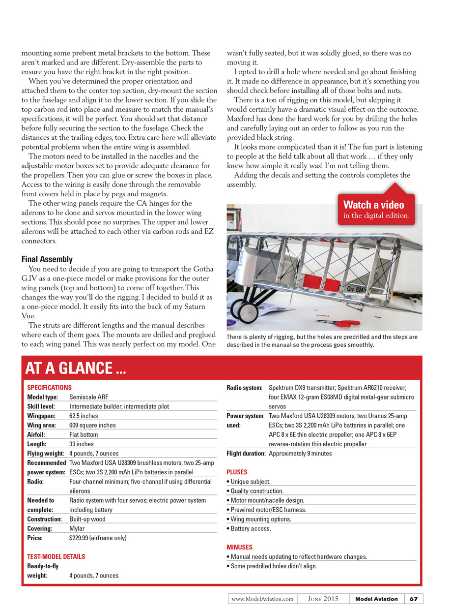
There is a ton of rigging on this model, but skipping it would certainly have a dramatic visual effect on the outcome. Maxford has done the hard work for you by drilling the holes and carefully laying out an order to follow as you run the provided black string.
It looks more complicated than it is! The fun part is listening to people at the field talk about all that work ... if they only knew how simple it really was! I'm not telling them.
Adding the decals and setting the controls completes the assembly.
AT A GLANCE ...
SPECIFICATIONS
- Model type: Semiscale ARF
- Skill level: Intermediate builder; intermediate pilot
- Wingspan: 62.5 inches
- Wing area: 609 square inches
- Airfoil: Flat bottom
- Length: 33 inches
- Flying weight: 4 pounds, 7 ounces
- Recommended power system: Two Maxford USA U28309 brushless motors; two 25-amp ESCs; two 3S 2,200 mAh LiPo batteries in parallel
- Radio: Four-channel minimum; five-channel if using differential ailerons
- Needed to complete: Radio system with four servos; electric power system including battery
- Construction: Built-up wood
- Covering: Mylar
- Price: $229.99 (airframe only)
TEST-MODEL DETAILS
- Ready-to-fly weight: 4 pounds, 7 ounces
- Radio system: Spektrum DX9 transmitter; Spektrum AR6210 receiver; four EMAX 12-gram ES08MD digital metal-gear submicro servos
- Power system used: Two Maxford USA U28309 motors; two Uranus 25-amp ESCs; two 3S 2,200 mAh LiPo batteries in parallel; one APC 8 x 6E thin electric propeller; one APC 8 x 6EP reverse-rotation thin electric propeller
- Flight duration: Approximately 9 minutes
PLUSES
- Unique subject.
- Quality construction.
- Motor mount/nacelle design.
- Pre-wired motor/ESC harness.
- Wing mounting options.
- Battery access.
MINUSES
- Manual needs updating to reflect hardware changes.
- Some predrilled holes didn't align.
Control Throws and CG
I used the recommended throws and center of gravity (CG), which worked well. I set up the high rates as the recommended amounts and then a mid and low rate if needed. I also added a switch to turn differential ailerons on or off as desired. Because this is a big, slow bomber with a draggy airframe, I like the option of differential and it works well.
Flying
After three weeks of waiting for flyable weather, I finally made it to the field for some test flights. There was no problem taking off from the grass field except for a stiff crosswind. Upon leaving the ground, the airplane instantly wanted to weather-vane, but it was manageable. Controllability was very good, but I will probably increase the rudder throw slightly.
This is a calm-day airplane and I pushed the limits during the test flights. Gusts made it challenging, but the airplane never felt out of control. Stalls were interesting because I didn't get a feel for when one was going to happen. It sort of sneaked up on me, but when it stalled, it dropped straight ahead and recovered easily.
There is so much rigging that you'll want to avoid gliding.
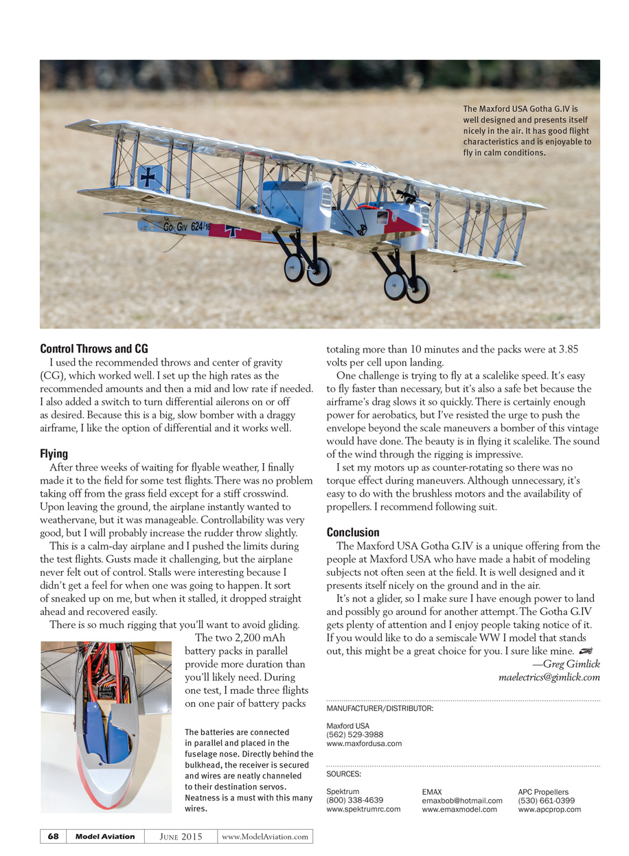
The two 2,200 mAh battery packs in parallel provide more duration than you'll likely need. During one test, I made three flights on one pair of battery packs totaling more than 10 minutes and the packs were at 3.85 volts per cell upon landing.
One challenge is trying to fly at a scale-like speed. It's easy to fly faster than necessary, but it's also a safe bet because the airframe's drag slows it so quickly. There is certainly enough power for aerobatics, but I've resisted the urge to push the envelope beyond the scale maneuvers a bomber of this vintage would have done. The beauty is in flying it scale-like. The sound of the wind through the rigging is impressive.
I set my motors up as counter-rotating so there was no torque effect during maneuvers. Although unnecessary, it's easy to do with the brushless motors and the availability of propellers. I recommend following suit.
Conclusion
The Maxford USA Gotha G.IV is a unique offering from the people at Maxford USA who have made a habit of modeling subjects not often seen at the field. It is well designed and it presents itself nicely on the ground and in the air.
It's not a glider, so I make sure I have enough power to land and possibly go around for another attempt. The Gotha G.IV gets plenty of attention and I enjoy people taking notice of it. If you would like to do a semiscale WWI model that stands out, this might be a great choice for you. I sure like mine.
—Greg Gimlick [email protected]
MANUFACTURER/DISTRIBUTOR:
- Maxford USA
- (562) 529-3988
- www.maxfordusa.com
SOURCES:
- Spektrum: (800) 338-4639 www.spektrumrc.com
- EMAX: [email protected] www.emaxmodel.com
- APC Propellers: (530) 661-0399 www.apcprop.com
Transcribed from original scans by AI. Minor OCR errors may remain.

