
Merlyn
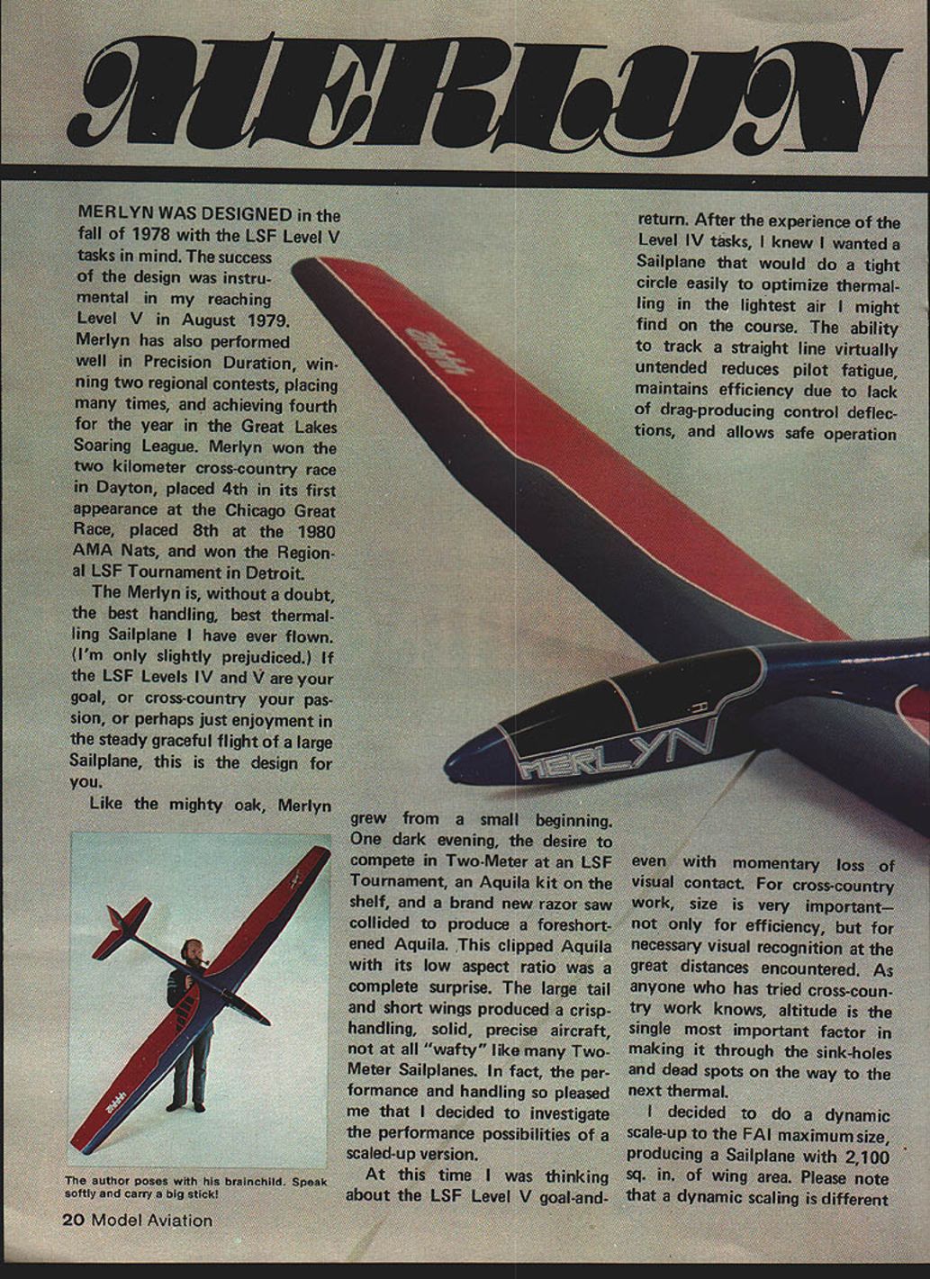
Merlyn was designed in the fall of 1978 with the LSF Level V tasks in mind. The success of the design was instrumental in my reaching Level V in August 1979. Merlyn has also performed well in Precision Duration, winning two regional contests, placing many times, and achieving fourth for the year in the Great Lakes Soaring League. Merlyn won the two-kilometer cross-country race in Dayton, placed 4th in its first appearance at the Chicago Great Race, placed 8th at the 1980 AMA Nats, and won the Regional LSF Tournament in Detroit.
The Merlyn is, without a doubt, the best-handling, best-thermalling sailplane I have ever flown (I'm only slightly prejudiced). If the LSF Levels IV and V are your goal, cross-country your passion, or you simply enjoy the steady, graceful flight of a large sailplane, this is the design for you.
Like the mighty oak, Merlyn grew from a small beginning. One dark evening, the desire to compete in Two-Meter at an LSF Tournament, an Aquila kit on the shelf, and a brand-new razor saw collided to produce a foreshortened Aquila. This clipped Aquila with its low aspect ratio was a complete surprise. The large tail and short wings produced a crisp-handling, solid, precise aircraft—not at all "wafty" like many Two-Meter sailplanes. In fact, the performance and handling so pleased me that I decided to investigate the performance possibilities of a scaled-up version.
At this time I was thinking about the LSF Level V goal-and-return. After the experience of the Level IV tasks, I knew I wanted a sailplane that would do a tight circle easily to optimize thermalling in the lightest air I might find on the course. The ability to track a straight line virtually untended reduces pilot fatigue, maintains efficiency due to lack of drag-producing control deflections, and allows safe operation even with momentary loss of visual contact. For cross-country work, size is very important—not only for efficiency, but for necessary visual recognition at the great distances encountered. As anyone who has tried cross-country work knows, altitude is the single most important factor in making it through the sink-holes and dead spots on the way to the next thermal.
I decided to do a dynamic scale-up to the FAI maximum size, producing a sailplane with 2,100 sq. in. of wing area. Note that dynamic scaling is different from dimensional scaling. For example, a 10% stab on a Two-Meter will not act the same as a 10% stab on a 2,100 sq. in. big bird. A different process is used, taking into account moments, areas, and damping factors to produce a model that handles the same even though dimensionally different.
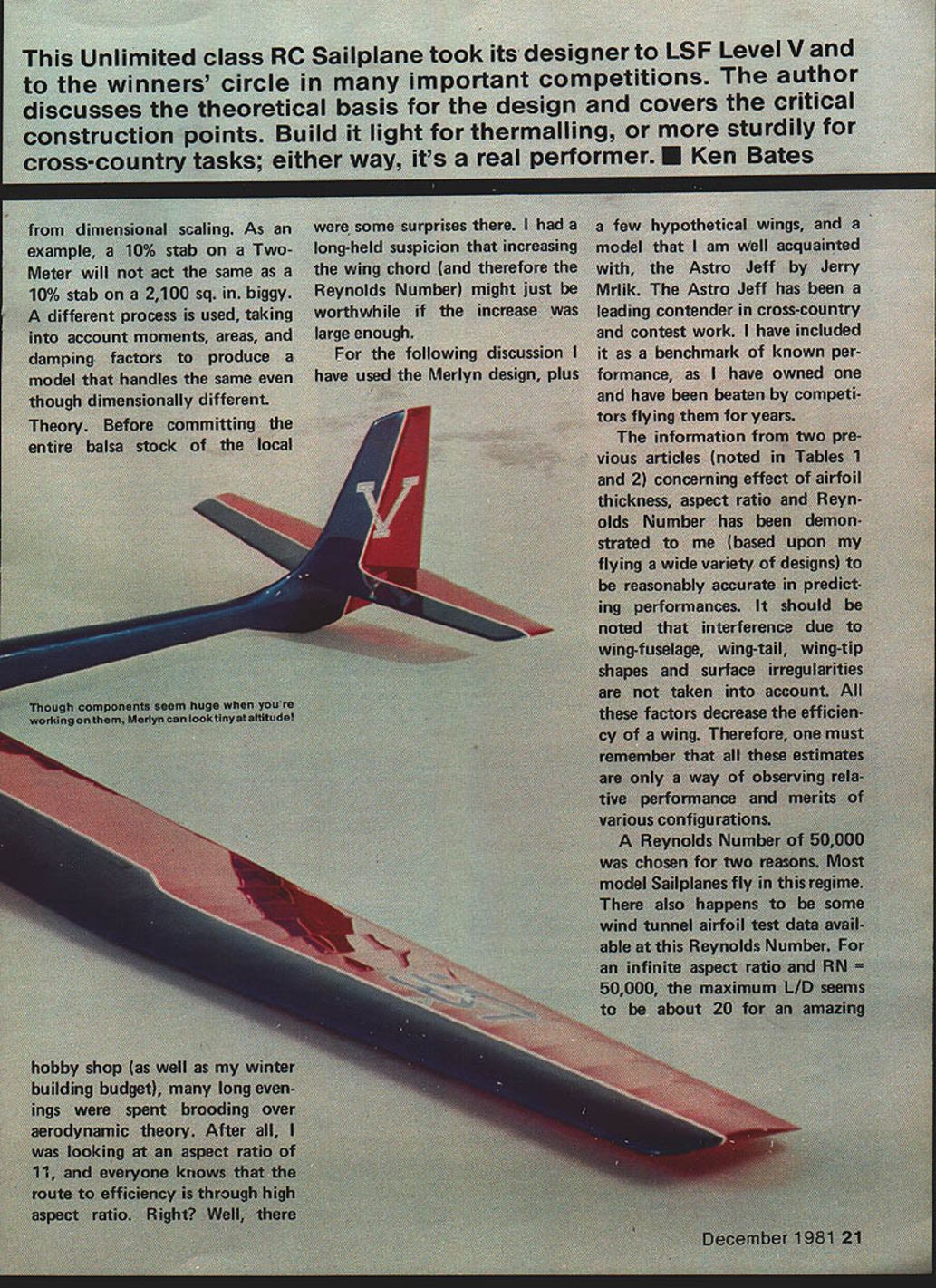
Theory. Before committing the entire balsa stock of the local hobby shop (as well as my winter building budget), many long evenings were spent brooding over aerodynamic theory. After all, I was looking at an aspect ratio of 11, and everyone knows the route to efficiency is through high aspect ratio. Right? Well, there were some surprises there. I had a long-held suspicion that increasing the wing chord (and therefore the Reynolds number) might just be worthwhile if the increase was large enough.
For the following discussion I have used the Merlyn design, plus a few hypothetical wings, and a model that I am well acquainted with, the Astro Jeff by Jerry Mrlik. The Astro Jeff has been a leading contender in cross-country and contest work. I have included it as a benchmark of known performance, as I have owned one and have been beaten by competitors flying them for years.
Information from two previous articles concerning the effect of airfoil thickness, aspect ratio, and Reynolds number has been demonstrated to me (based upon my flying a wide variety of designs) to be reasonably accurate in predicting performance. It should be noted that interference due to wing-fuselage, wing-tail, wing-tip shapes, and surface irregularities are not taken into account. All these factors decrease the efficiency of a wing. Therefore, one must remember that all these estimates are only a way of observing relative performance and merits of various configurations.
A Reynolds number of 50,000 was chosen for two reasons. Most model sailplanes fly in this regime. There also happens to be some wind-tunnel airfoil test data available at this Reynolds number. For an infinite aspect ratio and RN = 50,000, the maximum L/D seems to be about 20 for an amazing range of airfoils; L/D values range from 18 for thick, highly cambered airfoils to 24 for low-cambered ones. Table 1 describes the corrections for finite aspect ratios and wing thickness.
For a given chord, airspeed, and airfoil, increasing the aspect ratio will bring about an increase in L/D. Anyone who has stretched the span of a model without changing airfoil, chord, or weight (at least not much) will know that this relationship is true. Also note that, all other things being equal, thicker airfoils tend to have lower L/Ds.
What happens when we design around area-based rules (like FAI) rather than span? For a given area, an increase in aspect ratio brings about a reduction in the average chord of the wing, and therefore a lower Reynolds number for a given airspeed. Reynolds number can be considered a measure of scale effect, and in our range of airspeed, also a measure of relative efficiency. Indeed, data in the paper by S. J. Miley demonstrates an increase in L/D for Reynolds numbers up to about 1,000,000. Using the values of L/D vs. Reynolds number from the Miley paper and the correction factor from Table 1, a maximum possible L/D value can be calculated. These values are shown in Table 2 for the various configurations. Again, keep in mind that these are maximum possible L/D values and will in reality be less due to wing-tip losses, fuselage drag, and surface imperfections. However, a definite trend becomes apparent: a sufficient increase in wing chord can definitely outweigh the advantages of high aspect ratio.
Minimum sinking speed also depends on wing loading, camber, and aspect ratio. Table 3 would seem to favor higher aspect ratios. However, for the same wing area it would be very difficult to build a high-aspect-ratio aircraft with the same wing loadings as the low-aspect-ratio one.
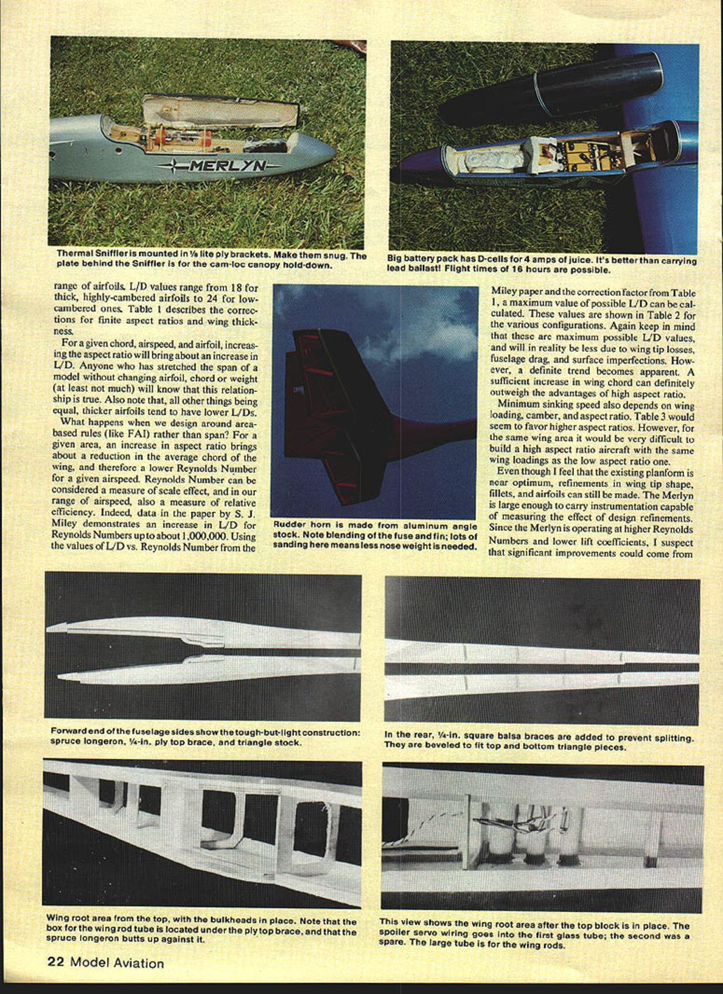
Even though I feel that the existing planform is near optimum, refinements in wingtip shape, fillets, and airfoils can still be made. The Merlyn is large enough to carry instrumentation capable of measuring the effect of design refinements. Since the Merlyn is operating at higher Reynolds numbers and lower lift coefficients, I suspect significant improvements could come from using airfoils not normally considered and from careful sanding; less nose weight would be needed.
Design is a game of compromise. I have designed the Merlyn according to my preferences in handling and indications of higher possible efficiency. Obviously, if not constrained to FAI size limits, I could do better using a higher-aspect-ratio wing with the same chord. However, world record attempts, Great Race rules, and most cross-country events require compliance to FAI rules. I also prefer the structural integrity inherent in such a configuration. The Merlyn is a very rugged aircraft, which is very encouraging when paying for all that wood.
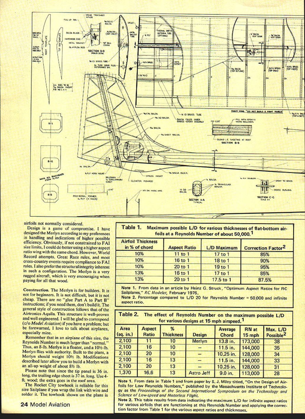
Construction
The Merlyn is for builders. It is not for beginners. It is not difficult, but it is not cheap. There are no "glue Part A to Part B" instructions; if you need them, don't build it. The general style of construction follows that of the Airtronics Aquila. This structure is well-proven and well engineered. I'll be glad to correspond (c/o Model Aviation) if you have a problem; but be forewarned, I love to talk about airplanes, especially mine.
Remember that in an airplane of this size, the Reynolds number is much larger than "normal." Thus, an 8-lb. Merlyn is a floater, and a 10-1/2-lb. Merlyn flies with authority. Built to the plans, a Merlyn should weigh 10-1/2 lb. Modifications described later allow you to build a Merlyn with an all-up weight of about 8-1/2 lb.
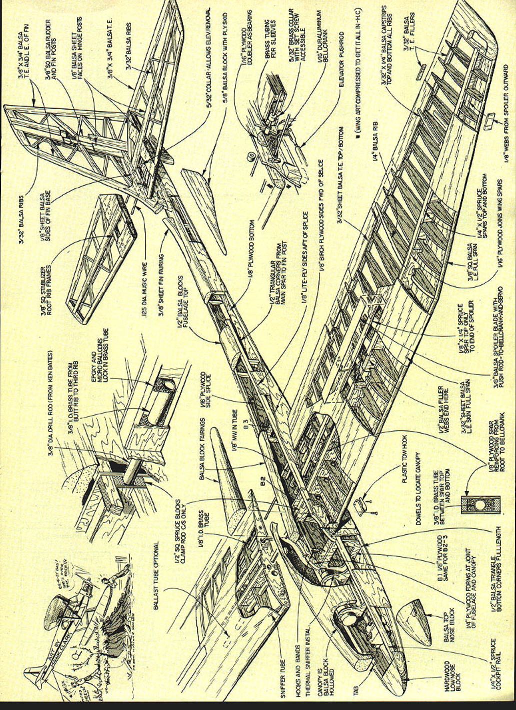
Please note that since the tip panel is 36 in. long, the trailing-edge sheet is 37 in. long. Use 4-ft. wood; the extra goes in the roof area.
The Rocket City hook is reliable for this size sailplane if you wrap the link with wire and solder it. The tow hook shown on the plans is made from an aluminum "T" extrusion purchased at a local hardware store. The rearward location is preferred for 12-volt winch launches. A weaker winch or hi-start (3/4-in. rubber) would use the forward location.
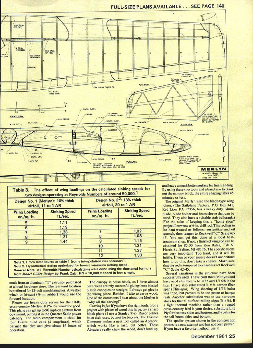
Please use heavy-duty servos for the 10-lb. cross-country Merlyn. KPS-15s would be good. This plane can get up to 90 mph on a return from downwind, putting it in the Quarter Scale power category. The radio compartment is sized for four D-size NiCd cells (4 amp/hour), which balance the bird and give about 16 hours of operation.
The canopy is balsa block, as I have almost never been entirely successful gluing those blasted plastic canopies on straight; I always get glue in the wrong place. Besides, I like to carve wood. One of the comments I hear about the Merlyn is, "Why all that carving?"
Carving is fun if you have the right tools. For a project with pieces of wood this large, try a sharp block plane (I use a Stanley 9-1/2). Razor planes have their uses, but not for big cuts. The Disston Company makes a neat tool called an Abrader, which works like a rasp, but better. These Abraders really chew the wood, don't load up, and leave a much better surface for final sanding. By using these two tools and a band saw to blank out the canopy block, the entire shaping takes 45 minutes or less.
The original Merlyn used the blade-type wing joiner. (The Sailplane Factory, P.O. Box 341, Red Lion, PA 17356, has a heavy-duty 14mm blade, blade holder, and brass sleeve that can be used. They also have a suitable stab bellcrank.) For the sake of keeping this a "home shop" project I now use a 3/8-in. drill rod. This rod has to be heat-treated as follows: austenitize and oil quench, then temper to Rockwell C Scale 42–45. You can get this done at a local heat-treatment shop. If not, a finished wing rod can be obtained for $5.00 from Ken Bates, 738 N. Harris St., Saline, MI 48176. The specifications are very important! Too hard, and it will be brittle. If you or your source doesn't understand how to do this, don't take a chance. Make sure that the rod is tempered to a hardness of Rockwell C Scale 42–45.
Several variations in the structure have been successfully used. I have built three Merlyns and have used ribs from 1/8 in. to 3/32 in. and 1/16 in. in the tip strips. I have also substituted 3/32 x 1/16 in. carbon-fiber spar (Flite-spar). Wing sheeting of 1/16 in. balsa was tried but proved to be too prone to hang up. Another substitute was to use narrow stock for the tail-surface trailing edges (1/8 x 3/8 in.). If a lighter machine rather than a rugged cross-country bird is your desire, substitute Lite Ply for the nose sides and bottom, and 1/8 in. balsa for the tail boom sides and bottom.
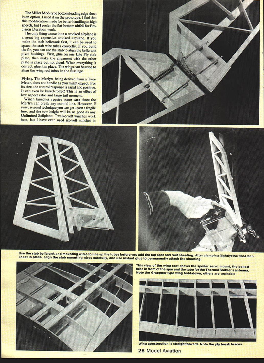
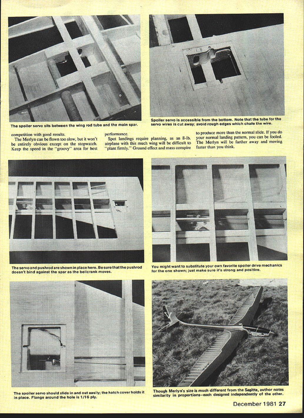
The spoiler system shown in the construction photos is a new attempt and has not been proven. If you have a favorite method, use it.
The Miller Mod-type bottom leading-edge sheet is an option. I used it on the prototype. I feel this modification made for better handling at high speeds, but I prefer the flat-bottom airfoil for Precision Duration work.
The only thing worse than a crooked airplane is a great big expensive crooked airplane. If you make the stab bellcrank first, it can be used to space the stab wire tubes correctly. If you build the fin, you can use the stab to align the bellcrank pivot bushings. First, glue on one Lite Ply stab plate, then make the alignment with the other plate in place but not glued. When everything is correct, glue it in place. The wings can be used to align the wing rod tubes in the fuselage.
Flying
The Merlyn, being derived from a Two-Meter, does not handle as you might expect. For its size, the control response is rapid and positive. It can even be barrel-rolled! This is an effect of low aspect ratio and large tail moment.
Winch launches require some care since the Merlyn can break any normal line. However, if you use good technique you can get up on a fragile line, and the tow height will be as good as any Unlimited sailplane. Twelve-volt winches work best, but I have even used six-volt winches in competition with good results.
The Merlyn can be flown too slow, but it won't be entirely obvious except on the stopwatch. Keep the speed in the "groovy" area for best performance.
Spot landings require planning, as an 8-lb. airplane with this much wing will be difficult to "plant firmly." Ground effect and mass conspire to produce more than the normal slide. If you do your normal landing pattern, you can be fooled. The Merlyn will be farther away and moving faster than you think.
Table 1. Maximum possible L/D for various thicknesses of flat-bottom airfoils at a Reynolds number of about 50,000
- Airfoil thickness 10% of chord, Aspect ratio 11:1 — L/D maximum 17:1 — Correction factor 85%
- Airfoil thickness 10% of chord, Aspect ratio 16:1 — L/D maximum 18:1 — Correction factor 90%
- Airfoil thickness 10% of chord, Aspect ratio 20:1 — L/D maximum 19:1 — Correction factor 95%
- Airfoil thickness 13% of chord, Aspect ratio 16:1 — L/D maximum 17:1 — Correction factor 85%
- Airfoil thickness 13% of chord, Aspect ratio 20:1 — L/D maximum 17.5:1 — Correction factor 87.5%
Notes:
- From data in an article by Heinz G. Struck, "Optimum Aspect Ratios for RC Sailplanes," RC Modeler, February 1976.
- Correction factor is percentage compared to L/D 20 for Reynolds number = 50,000 and infinite aspect ratio.
Table 2. The effect of Reynolds number on the maximum possible L/D for various designs at 15 mph airspeed
- Area 2,100 sq. in., Aspect ratio 11, Thickness 10% — Design: Merlyn — Average chord 13.8 in. — RN at 15 mph 173,000 — Max. L/D possible 38
- Area 2,100 sq. in., Aspect ratio 16, Thickness 10% — Design: — — Average chord 11.5 in. — RN at 15 mph 144,000 — Max. L/D possible 35
- Area 2,100 sq. in., Aspect ratio 20, Thickness 10% — Design: — — Average chord 10.25 in. — RN at 15 mph 128,000 — Max. L/D possible 34
- Area 2,100 sq. in., Aspect ratio 16, Thickness 13% — Design: — — Average chord 11.5 in. — RN at 15 mph 144,000 — Max. L/D possible 33
- Area 2,100 sq. in., Aspect ratio 20, Thickness 13% — Design: — — Average chord 10.25 in. — RN at 15 mph 128,000 — Max. L/D possible 31
- Area 1,370 sq. in., Aspect ratio 16.6, Thickness 13% — Design: Astro Jeff — Average chord 9.0 in. — RN at 15 mph 113,000 — Max. L/D possible 28
Notes:
- Data from Table 1 and from S. J. Miley, "On the Design of Airfoils for Low Reynolds Numbers," Proceedings of the Second International Symposium on the Technology and Science of Low-speed and Motored Flight, MIT.
- Values result from maximum L/D for infinite aspect ratios at this Reynolds number, applying the correction factor from Table 1 for various aspect ratios and thicknesses.
Table 3. The effect of wing loadings on the calculated sinking speeds for two designs operating at Reynolds numbers around 50,000
Design No. 1 (Merlyn): 10% thick airfoil, 11:1 AR
- Wing loading 5 oz./sq. ft. — Sinking speed 1.11 ft./sec.
- Wing loading 6 oz./sq. ft. — Sinking speed 1.19 ft./sec.
- Wing loading 7 oz./sq. ft. — Sinking speed 1.28 ft./sec.
- Wing loading 8 oz./sq. ft. — Sinking speed 1.37 ft./sec.
- Wing loading 9 oz./sq. ft. — Sinking speed 1.44 ft./sec.
Design No. 2: 13% thick airfoil, 20:1 AR
- Wing loading 7 oz./sq. ft. — Sinking speed 1.02 ft./sec.
- Wing loading 8 oz./sq. ft. — Sinking speed 1.08 ft./sec.
- Wing loading 9 oz./sq. ft. — Sinking speed 1.15 ft./sec.
- Wing loading 10 oz./sq. ft. — Sinking speed 1.21 ft./sec.
- Wing loading 11 oz./sq. ft. — Sinking speed 1.27 ft./sec.
- Wing loading 12 oz./sq. ft. — Sinking speed 1.33 ft./sec.
Transcribed from original scans by AI. Minor OCR errors may remain.

