
Micro-Flying
Dave Robelen
Route 4, Box 369, Farmville VA 23901; Email: [email protected]
GREETINGS from chilly central Virginia. As I am writing this, it is early December. By the time you read it, it will be winter and Christmas will have passed.
I hope all of you had a safe and joyous Christmas and found just what you were looking for under the tree. With the rapid growth of the micro industry, there certainly is plenty from which to choose.
In the last column I indicated that the next National Indoor Remote-controlled Aircraft Council (NIRAC) Championships would probably be held in Pennsylvania. There has been a change, and it appears that we will be back in Waterford, Michigan, in 2005.
This year the Contest Director will be Bob Wilder, so you can expect him to do a quality job running the meet. Make plans now to come out and join the fun. More periods of organized open flying are planned, so even if you are not a “trophy hound,” come on out.
Rising star: Scott Christensen
There is a rising star in the field of micromodels. Scott Christensen, a manager with Sig Manufacturing, is no stranger to quality modeling. Roughly a year ago he was bitten by the micro bug and obtained an RFFS-100 control system. In practically no time, Scott had a new design flying that he calls the Yardsail. I saw it at the Toledo Show and again in Waterford, and I was delighted with the obvious quality and good flying habits.
The model is a profile shoulder wing with three-panel dihedral, and the drive is mounted on a low pylon over the wing. Although the model is not complex, the quality and finish are superb.
Last season I published plans for a 14-inch-span, all-balsa WACO SRE built for micro gear and drive. This was a project in RC MicroFlight. Shortly after the issue was published, I received an email with pictures attached from Scott. He is a fan of the WACO SRE and had built his own from my plans.
Scott’s model was incredibly clean, lightweight, and had a true scale color scheme. It flew quite well, which led to stage two: he decided to build another to contest standards.
It was hard for me to imagine much of an improvement over the first model. That changed when I received another email from him. The latest version of Scott’s WACO is stunning! Unless you know the size, you would naturally assume it is a much larger model. It took right off and flew like a bird.
I do not have pictures large enough to show here, but for those who have Internet access, check out www.rcgroups.com for a real treat in photos.
Carving propellers
I have been carving my own propellers from wood for a long time, and when I applied this technique to small electric-powered models, the improvement in performance was evident.
There is no mystery to shaping a propeller; it is a matter of proper layout and careful cutting. I cannot claim credit for this design system. It has been in use for at least 50 years and produces an accurate, well-performing blade.
The layout method:
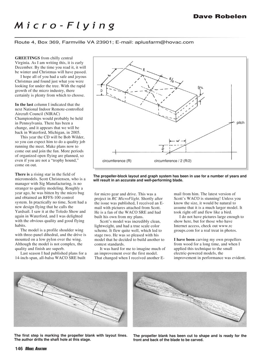
- The accompanying sketch (described here) shows the circumference of a propeller marked along the bottom line, with the pitch marked on a vertical line.
- For convenience I usually divide both of these numbers by two or three so they will fit a standard sheet of paper. Dividing the circumference by two and marking the line will designate a point halfway out on one blade.
- Drawing a slanted line between this point and the pitch mark will define the pitch angle at the middle of the blade.
- The maximum chord of the blade may be marked on this line, and then a pair of lines defining the block measurements may be drawn.
- The figure shows a drawing of a typical propeller-block layout; the same basic layout will apply to any size propeller.
Materials and tools:
- For most applications, hard balsa will make a satisfactory propeller.
- I use an X-Acto knife with a #26 whittler's blade to shape the blank after cutting it out with a jigsaw.
- For a sturdier propeller, clear white pine (available at home-improvement stores) works well; in that case I do much of the carving with a drum-sanding attachment on a Moto-Tool.
- Accuracy when drilling the shaft hole and cutting the blank pays off later in a true-running propeller.
Shaping steps:
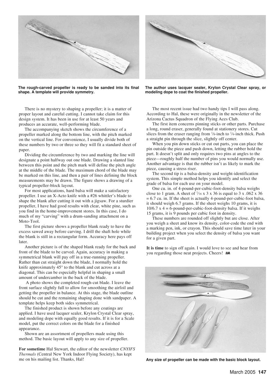
- Start with a propeller blank and saw away excess before carving. Drill the shaft hole while the blank is still rectangular for better accuracy.
- Shape the blank symmetrically; accuracy yields a true-running prop.
- Rather than cut straight down the blade, I normally hold the knife at approximately 45° and cut across at a diagonal. This is especially helpful for shaping a small amount of undercamber in the back of the blade.
- After the rough cut, leave the front surface slightly full to allow for smoothing the airfoil and achieving balance.
- At this stage, cut the blade outline and do the remaining shaping with sandpaper. A template helps keep both sides symmetrical.
Finishing:
- The finished propeller can be sealed or coated. I have used lacquer sealer, Krylon Crystal Clear spray, and modeling dope with equally good results.
- For scale models, paint the correct colors on the blade for a finished appearance.
Tips from CNYIFS Thermals (via Hal Stewart)
For some time Hal Stewart, editor of the newsletter CNYIFS Thermals (Central New York Indoor Flying Society), has kept me on his mailing list. Thanks, Hal! The most recent issue had two handy tips originally from the Arizona Cactus Squadron of the Flying Aces Club.
1) Pinning small parts
- Purchase a long, round eraser (found at stationery stores).
- Cut slices from the eraser ranging from 1/8-inch to 1/4-inch thick.
- Push a straight pin through the slice, slightly off center.
- When you pin down sticks or cut out parts, place the pin outside the piece and push down, letting the rubber hold the part. It doesn't split and typically only requires two pins at angles to the piece—roughly half the number of pins you would normally use.
- The rubber is less likely to mark the piece, avoiding a stress riser.
2) Balsa-density and weight identification
- One cubic inch of 4-pound-per-cubic-foot-density balsa weighs close to 1 gram.
- A sheet 1/16 x 3 x 36 inches has a volume of 3 x 0.0625 x 36 = 6.75 cu. in.
- If the sheet is truly 4-lb/cu ft balsa, it should weigh about 6.75 grams.
- If the sheet weighs 10 grams, its density is (10 / 6.75) x 4 ≈ 6 lb/cu ft.
- If it weighs 15 grams, it is about (15 / 6.75) x 4 ≈ 9 lb/cu ft.
- These numbers are rounded but close. After you weigh a sheet and know its density, color-code the end with a marker, ink, or crayon. This saves time later when selecting the density of balsa for specific parts.
It is time to sign off again. I would love to see and hear from you regarding those neat projects. Cheers!
Transcribed from original scans by AI. Minor OCR errors may remain.

