
Micro-Scale Warbirds
Learn what it takes to build palm-size foam fighters
by Martin Newell
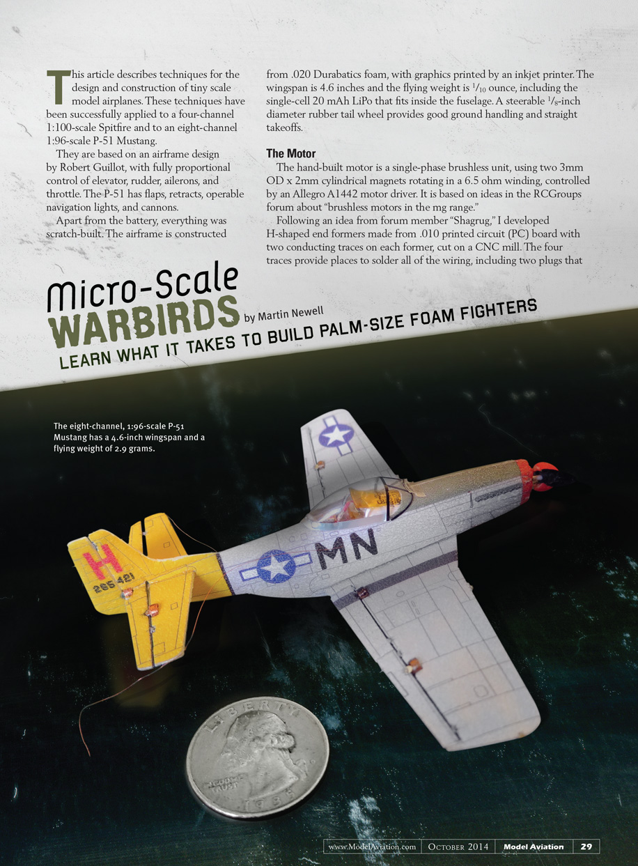
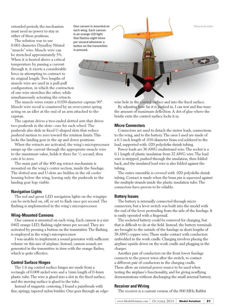
This article describes techniques for the design and construction of tiny scale model airplanes. These techniques have been successfully applied to a four-channel, 1:100-scale Spitfire and to an eight-channel, 1:96-scale P-51 Mustang.
They are based on an airframe design by Robert Guillot, with fully proportional control of elevator, rudder, ailerons, and throttle. The P-51 has flaps, retracts, operable navigation lights, and cannons.
Apart from the battery, everything was scratch-built. The airframe is constructed from 0.020-inch Durabatic foam, with graphics printed by an inkjet printer. The wingspan is 4.6 inches and the flying weight is 1/10 ounce, including the single-cell 20 mAh LiPo that fits inside the fuselage. A steerable 1/8-inch-diameter rubber tail wheel provides good ground handling and straight takeoffs.
The Motor
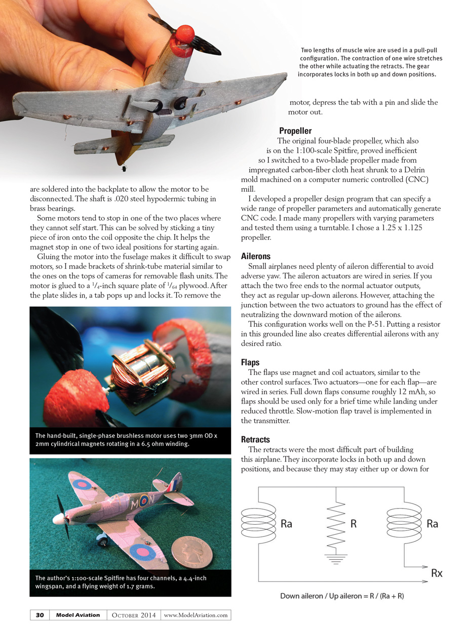
The hand-built motor is a single-phase brushless unit, using two 3 mm OD x 2 mm cylindrical magnets rotating in a 6.5 ohm winding, controlled by an Allegro A1442 motor driver. It is based on ideas in the RCGroups forum about "brushless motors in the mg range."
Following an idea from forum member "Shagrug," I developed H-shaped end formers made from 0.010-inch printed circuit (PC) board with two conducting traces on each former, cut on a CNC mill. The four traces provide places to solder all of the wiring, including two plugs that are soldered into the backplate to allow the motor to be disconnected. The shaft is 0.020-inch steel hypodermic tubing running in brass bearings.
Some motors tend to stop in one of the two positions where they cannot self-start. This can be solved by sticking a tiny piece of iron onto the coil opposite the chip. It helps the magnet stop in one of two ideal positions for starting again.
Gluing the motor into the fuselage makes it difficult to swap motors, so I made brackets of shrink-tube material similar to the ones on the tops of cameras for removable flash units. The motor is glued to a 1/4-inch square plate of 1/64-inch plywood. After the plate slides in, a tab pops up and locks it. To remove the motor, depress the tab with a pin and slide the motor out.
Propeller
The original four-blade propeller, which also is on the 1:100-scale Spitfire, proved inefficient, so I switched to a two-blade propeller made from impregnated carbon-fiber cloth heat-shrunk to a Delrin mold machined on a computer numeric controlled (CNC) mill.
I developed a propeller design program that can specify a wide range of propeller parameters and automatically generate CNC code. I made many propellers with varying parameters and tested them using a turntable. I chose a 1.25 x 1.125 propeller.
Ailerons
Small airplanes need plenty of aileron differential to avoid adverse yaw. The aileron actuators are wired in series. If you attach the two free ends to the normal actuator outputs, they act as regular up-down ailerons. However, attaching the junction between the two actuators to ground has the effect of neutralizing the downward motion of the ailerons.
This configuration works well on the P-51. Putting a resistor in this grounded line also creates differential ailerons with any desired ratio.
Flaps
The flaps use magnet-and-coil actuators, similar to the other control surfaces. Two actuators—one for each flap—are wired in series. Full-down flaps consume roughly 12 mAh, so flaps should be used only briefly while landing under reduced throttle. Slow-motion flap travel is implemented in the transmitter.
Retracts
The retracts were the most difficult part of building this airplane. They incorporate locks in both up and down positions, and because they may stay either up or down for extended periods, the mechanism must need no power to stay in either of these positions.
The solution was to use 0.001-inch-diameter Dynalloy Nitinol "muscle" wire. Muscle wire can be stretched approximately 5%. When it is heated above a critical temperature by passing a current through it, it exerts a considerable force as it attempts to contract to its original length. Two lengths of muscle wire are used in a pull-pull configuration, in which the contraction of one wire stretches the other while simultaneously actuating the retracts.
The muscle wires rotate a 0.030-inch-diameter capstan 90°. Muscle wire recoil is countered by an over-center spring acting on an idler at the end of an arm attached to the capstan.
The capstan drives a two-ended slotted arm that drives two pushrods in the slots—one for each wheel. The pushrods also slide in fixed U-shaped slots that reduce pushrod motion to zero toward the rotation limits. This locks the landing gear in the up and down positions.
When the retracts are activated, the wing's microprocessor ramps the current through the appropriate muscle wire to the maximum value, holds it there for 1/2 second, then cuts it to zero.
The main part of the 400 mg retract mechanism is mounted on the wing's center section, inside the fuselage. The slotted arm and U-slots are hidden in the oil cooler housing below the wing, leaving only the pushrods to the landing gear legs visible.
Navigation Lights
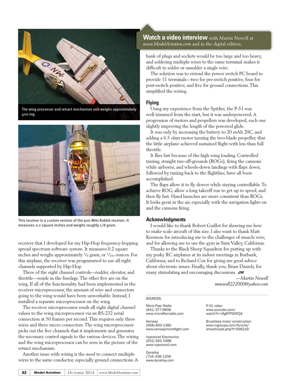
The red and green LED navigation lights on the wingtips can be switched on, off, or set to flash once per second. The flashing is implemented in the wing's microprocessor.
Wing-Mounted Cannons
One cannon is mounted on each wing. Each cannon is a size 0402 orange LED, flashing eight times per second. They are activated by pressing a button on the transmitter. The flashing is generated by the wing's microprocessor.
I was unable to implement a sound generator with sufficient volume on this size of airplane. Instead, cannon sounds are generated in the transmitter in time with the orange flashes, which is quite effective.
Control Surface Hinges
The 1.6 mg control surface hinges are made from a rectangle of 0.008-inch nickel wire and a 1 mm length of 0.4 mm plastic tube. The wire is glued into a slot in the fixed surface, and the moving surface is glued to the tube.
Instead of magnetic centering, I used a paintbrush bristle with fine, springy, tapered nylon bristles. One bristle goes through an edge-wise hole in the control surface and into the fixed surface. By adjusting how far it is pushed in, I can test and fine-tune the amount of maximum deflection. A dot of glue where the bristle exits the control surface locks it in.
Micro Connectors
Connectors are used to detach the motor leads, connections to the wing, and the battery. The ones I used are made from a 0.1-inch length of 0.010-inch-diameter brass rod soldered to the lead, supported with 0.020-inch polyolefin shrink tubing.
Power leads are 36 AWG multistrand wire. The socket is a 0.1-inch length of plastic insulation from 32 AWG wire. The lead wire is stripped, pushed through the insulation, then folded back; the insulated lead wire is also folded against the tubing.
The entire ensemble is covered with 0.020-inch polyolefin shrink tubing. Contact is made when the brass pin is squeezed against the multiple strands inside the plastic insulation tube. The connectors have proven to be reliable.
Battery Issues
The battery is internally connected through micro connectors, but a lever switch was built into the model with the end of the lever protruding from the side of the fuselage. It is easily operated with a fingernail.
The socketed battery could be removed for charging, but that is difficult to do at the field. Instead, the battery terminals are brought to the outside of the fuselage as short lengths of 38 AWG copper wire. These make contact with conductors embedded in the work cradle. Charging involves placing the airplane upside down on the work cradle and plugging in the charger.
Another pair of conductors on the front lower fuselage connects to the power wires after the switch, to contact a different pair of conductors in the charging cradle. These allow an external power source to be used when testing the airplane's functionality, and for giving nonflying demonstrations without discharging the small internal battery.
Receiver and Wiring
The receiver is a custom version of the 900 MHz Rabbit receiver that I developed for my Hip-Hop frequency-hopping spread-spectrum software system. It measures 0.2 square inches and weighs approximately 1/8 gram (about 1/250 ounce). For this airplane, the receiver was programmed to use all eight channels supported by Hip-Hop.
Three of the eight channel controls—rudder, elevator, and throttle—reside in the fuselage. The other five are on the wing. If all of the functionality had been implemented in the receiver microprocessor, the amount of wire and connectors going to the wing would have been unworkable. Instead, I installed a separate microprocessor on the wing.
The receiver microprocessor sends all eight digital channel values to the wing microprocessor via an RS-232 serial connection at 50 frames per second. This requires only three wires and three micro connectors. The wing microprocessor picks out the five channels that it implements and generates the necessary control signals to the various devices. The wiring and the wing microprocessor can be seen in the picture of the retract mechanism.
Another wiring issue is the need to connect multiple wires to the same conductor, especially ground connections. A bank of plugs and sockets would be too large and too heavy, and soldering multiple wires to the same terminal makes it difficult to solder or unsolder a single wire.
The solution was to extend the power-switch PC board to provide 11 terminals—two for pre-switch positive, four for post-switch positive, and five for ground connections. This simplified the wiring.
Flying
Using my experience from the Spitfire, the P-51 was well trimmed from the start, but it was underpowered. A progression of motors and propellers was developed, each one slightly improving the length of the powered glide.
It was only by increasing the battery to a 20 mAh 20C unit and adding a 6.5-ohm motor turning the two-blade propeller that the little airplane achieved sustained flight with less than full throttle.
It flies fast because of the high wing loading. Controlled taxiing, straight rise-off-ground (ROG) takeoffs, firing the cannons while airborne, and wheels-down landings with flaps down, followed by taxiing back to the flightline, have all been accomplished.
The flaps allow it to fly slower while staying controllable. To achieve ROG, allow a long takeoff run to get up to speed, then fly fast. Hand launches are more consistent than ROGs. It looks great in the air, especially with the navigation lights on and the cannons firing.
Acknowledgments
I would like to thank Robert Guillot for showing me how to make scale aircraft of this size. I also want to thank Matt Keennen for introducing me to the challenges of muscle wire, and for allowing me to use the gym in Simi Valley, California.
Thanks to the Black Sheep Squadron for putting up with my pesky RC airplanes at its indoor meetings in Burbank, California; and to Richard Cox for giving me good advice about electronic issues. Finally, thank you, Brian Daniels, for many stimulating and encouraging discussions.
—Martin Newell [email protected]
Sources
- Micro Flier Radio — (941) 377-9808 — www.microflieradio.com
- Kenway — (908) 850-1385 — www.kenwaymicroflight.com
- Injectorall Electronics — (631) 563-3388 — www.injectorall.com
- Dynalloy — (714) 436-1206 — www.dynalloy.com
- P-51 video — www.youtube.com/watch?v=J5gRTPGYEQA
- Brushless motor construction — www.rcgroups.com/forums/showthread.php?t=596219
Transcribed from original scans by AI. Minor OCR errors may remain.

