
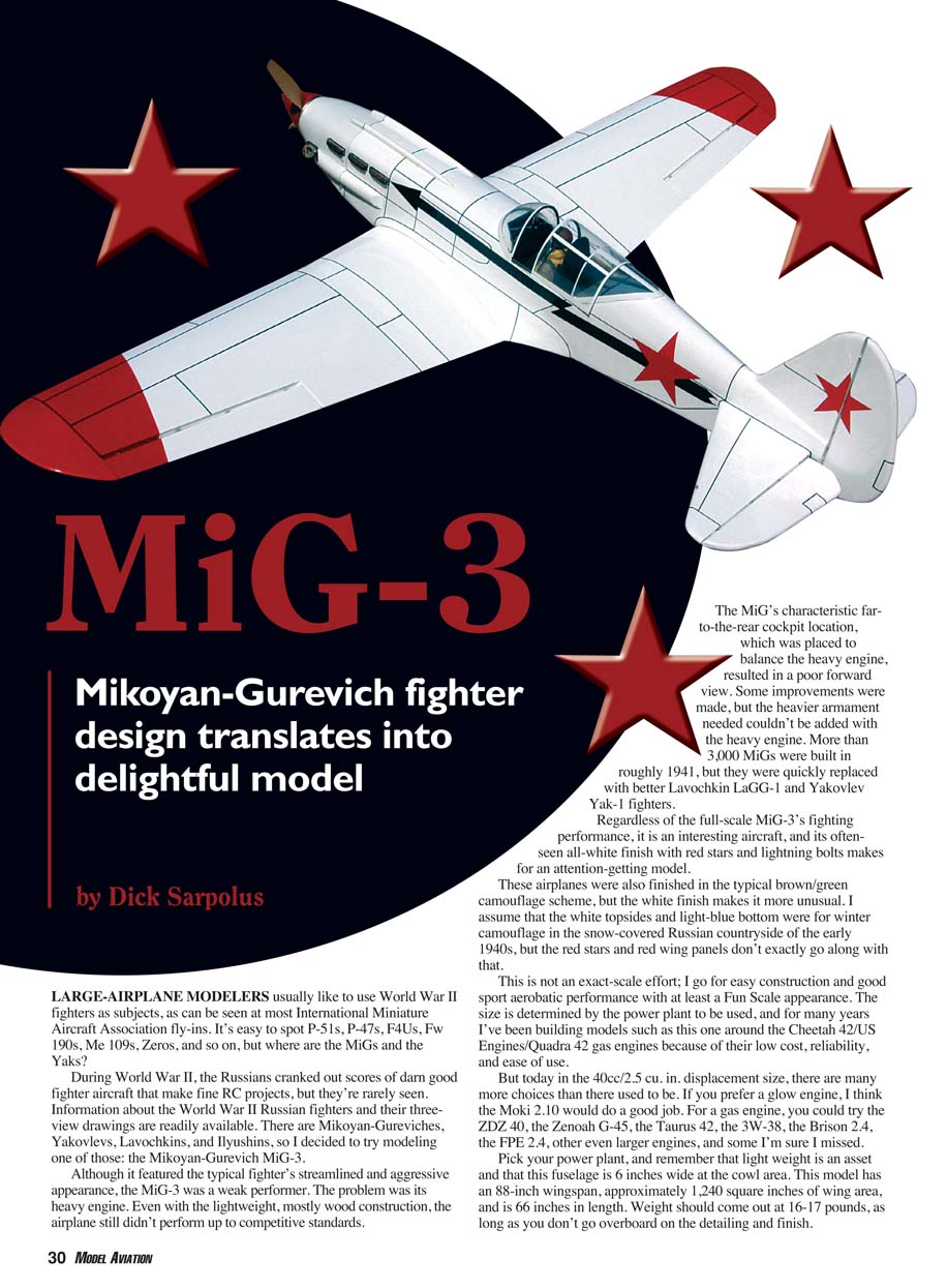
MiG-3
Mikoyan-Gurevich fighter design translates into delightful model
by Dick Sarpolus
Large-airplane modelers usually like to use World War II fighters as subjects, as can be seen at most International Miniature Aircraft Association fly-ins. It’s easy to spot P-51s, P-47s, F4Us, Fw 190s, Me 109s, Zeros, and so on, but where are the MiGs and the Yaks?
During World War II, the Russians cranked out scores of darn-good fighter aircraft that make fine RC projects, but they’re rarely seen. Information about the World War II Russian fighters and their three-view drawings are readily available. There are Mikoyan-Gureviches, Yakovlevs, Lavochkins, and Ilyushins, so I decided to try modeling one of those: the Mikoyan-Gurevich MiG-3. Although it featured the typical fighter’s streamlined and aggressive appearance, the MiG-3 was a weak performer. The problem was its heavy engine. Even with lightweight, mostly wood construction, the airplane still didn’t perform up to competitive standards.
The MiG’s characteristic far-to-the-rear cockpit location, placed to balance the heavy engine, resulted in a poor forward view. Some improvements were made, but the heavier armament needed couldn’t be added with the heavy engine. More than 3,000 MiGs were built in roughly 1941, but they were quickly replaced with better Lavochkin LaGG-1 and Yakovlev Yak-1 fighters.
Regardless of the full-scale MiG-3’s fighting performance, it is an interesting aircraft, and its often-seen all-white finish with red stars and lightning bolts makes for an attention-getting model. These airplanes were also finished in the typical brown/green camouflage scheme, but the white finish makes it more unusual. I assume that the white topsides and light-blue bottom were for winter camouflage in the snow-covered Russian countryside of the early 1940s, but the red stars and red wing panels don’t exactly go along with that.
This is not an exact-scale effort; I build for easy construction and good sport-aerobatic performance with at least a fun-scale appearance. The size is determined by the power plant to be used, and for many years I’ve been building models such as this one around the Cheetah 42 / US Engines / Quadra 42 gas engines because of their low cost, reliability, and ease of use. Today in the 40cc / 2.5 cu. in. displacement size there are many more choices than there used to be.
If you prefer a glow engine, the Moki 2.10 would do a good job. For gas engines, consider the ZDZ 40, the Zenoah G-45, the Taurus 42, the 3W-38, the Brison 2.4, the FPE 2.4, or other similar engines. Pick your power plant, and remember that light weight is an asset — this fuselage is 6 inches wide at the cowl area.
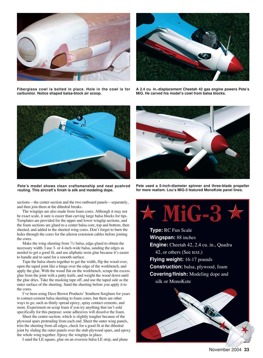
This model has an 88-inch wingspan, approximately 1,230 square inches of wing area, and is about 67 inches in length. Weight should come out at 16–17 pounds, as long as you don’t go overboard on the detailing and finish.
If you want a true scale MiG-3, plans are available from Roamin' Research, 37137 Clubhouse Dr., Sterling Heights, MI 48312. It sells a larger model that uses larger engines. If you are interested in a fun-scale, quickly and easily built MiG-3 with foam-core surfaces, a somewhat boxy fuselage, fixed gear, and sporty aerobatic flight, consider this one.
I prefer to use a semi-symmetrical airfoil on these types of models because many modelers add scale detailing, retracts, and better finishing. This model uses cut-foam wing cores, wingtip cores, fuselage topblock cores, and tail-section foam cores. I’ve found foam-core construction to be quick, simple, economical, and reasonably light for these sport projects. A plastic canopy is available; it was made for a larger scale MiG and can be trimmed for this one.
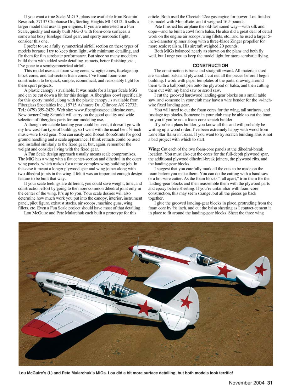
Both Lou and Pete used the Cheetah 42cc gas engine for power. Lou finished his model with MonoKote and it weighed 16.5 pounds. Pete finished his airplane the old-fashioned way — with silk and dope — and he built a cowl from balsa. He also did a great deal of detail work on the engine air scoops, wing fillets, etc., and he used a larger 5-inch-diameter spinner along with a three-blade Zinger propeller for more scale realism. His aircraft weighed 20 pounds.
Both MiGs balanced nearly as shown on the plans and both fly well, but I urge you to keep the model light for more aerobatic flying.
CONSTRUCTION
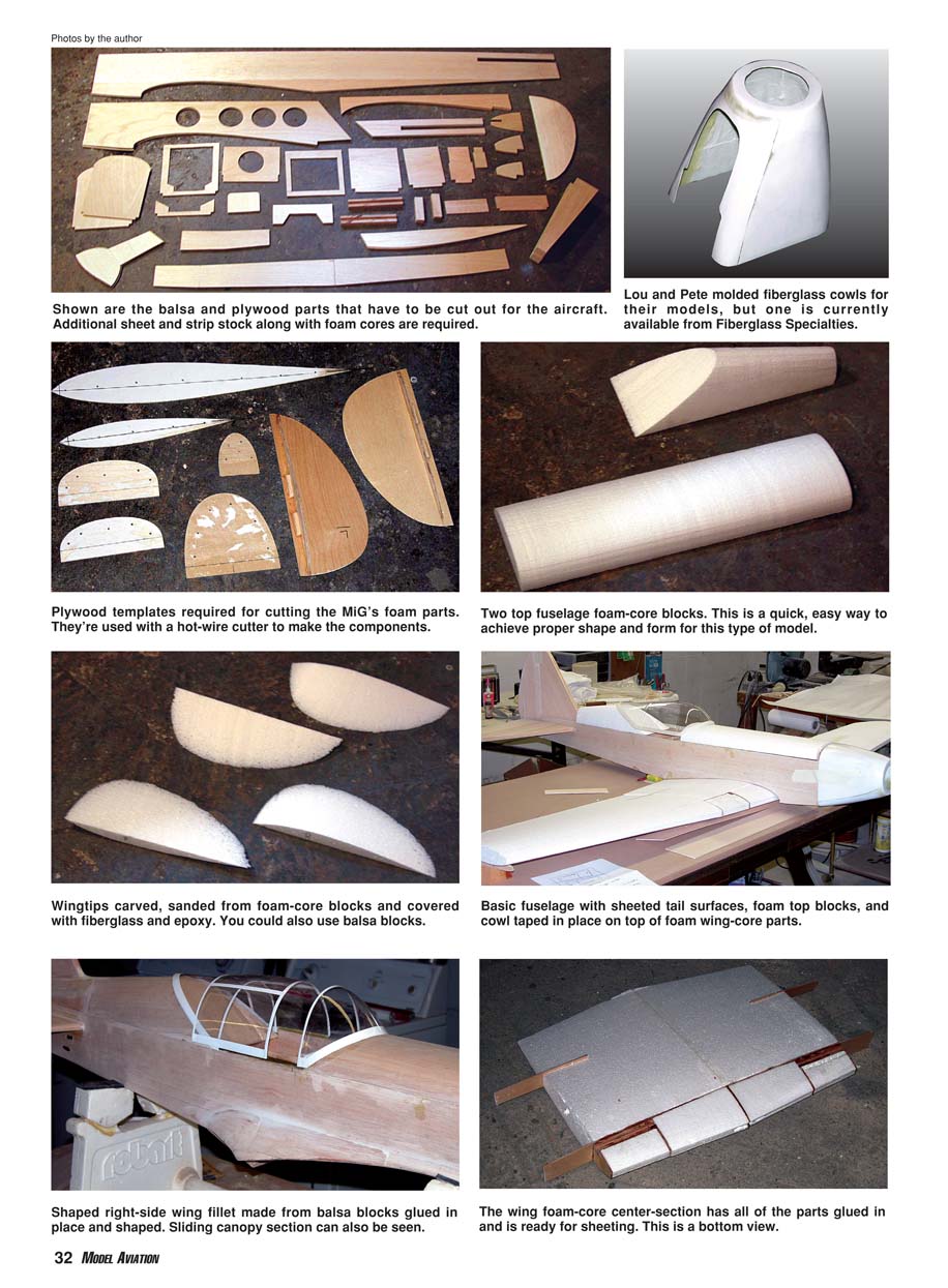
The construction is basic and straightforward. All materials used are standard balsa and plywood. I cut out all the pieces before I begin building. I work with paper templates of the parts, drawing around them with a ballpoint pen onto the plywood or balsa, and then cutting them out with my band saw or scroll saw.
I cut the grooved hardwood landing-gear blocks on a small table saw, and someone in your club may have a wire bender for the 1/4-inch wire fixed landing gear.
You will need to cut the foam cores for the wing, tail surfaces, and fuselage top blocks. Someone in your club may be able to cut the foam for you if you're not a foam-core scratch builder.
If you're a plans builder, you know all this and will probably be writing up a wood order; I’ve been extremely happy with wood from Lone Star Balsa in Texas. If you want to try scratch building, this is not a bad project with which to start.
Wing
- Cut each of the two foam-core panels at the dihedral-break location.
- Cut the cores for the full-depth plywood spar, the additional plywood dihedral-break joiners, the plywood ribs, and the landing-gear blocks.
- Carefully mark all the cuts on the foam before you make them. You can do the cutting with a band saw or a hot-wire cutter.
- As the foam blocks are cut, trim them for the landing-gear blocks and then reassemble them with the plywood parts and epoxy before sheeting. If you're unfamiliar with foam-core construction, this may seem strange, but all the pieces go back together.
Glue the grooved landing-gear blocks in place, protruding from the foam core by 3/32 inch, and cut the balsa sheeting as you contact-cement it in place to fit around the landing-gear blocks. Sheet the three wing sections — the center section and the two outboard panels — separately, and then join them at the dihedral breaks.
The wingtips are also made from foam cores. Although it may not be exact scale, it sure is easier than carving large balsa blocks for tips. Templates are provided for the upper and lower wingtip sections. The foam sections are glued to a center balsa core, top and bottom, then sheeted and added to the sheeted wing cores. Don't forget to burn the holes through the cores for the aileron extension cables before joining the cores.
Make the wing sheeting from 3/32-inch balsa, edge-glued to obtain the necessary width. I use 3- or 4-inch-wide balsa, sanding the edges as needed to get a good fit, and use aliphatic-resin glue because it's easier to handle and to sand for a smooth surface.
Tape the balsa sheets together to get the width, flip the wood over, open the taped joint like a hinge over the edge of the workbench, and apply the glue. With the wood flat on the workbench, scrape the excess glue from the joint with a putty knife, and weight the wood down until the glue dries. Take the masking tape off, and use the taped side as the outer surface of the sheeting. Sand the sheeting before you apply it to the cores.
I've been using Dave Brown Products' Southern Sorghum for years to contact-cement balsa sheeting to foam cores, but there are other options such as thinly spread epoxy or spray contact cements. Experiment on scrap foam if you try anything that isn't sold specifically for this purpose; some adhesives will dissolve the foam.
Sheet the center section, which is slightly tougher because of the plywood spars protruding from each end. Sheet the outer wing panels, trim the sheeting from all edges, check for a good fit at the dihedral joint by sliding the outer panels over the stub plywood spars, and epoxy the whole wing together. Epoxy the wingtips in place.
I sand the leading edge square, glue on an oversize balsa LE strip, and sand it to shape. Then I cut a slot through the LE for the plywood wing-mounting tab and epoxy it in place after the wing has been fitted to the fuselage saddle.
I recommend wrapping the two wing dihedral joints with medium-weight fiberglass cloth and epoxy. Be sure to scrape off excess epoxy with a piece of cardboard, leaving just enough to saturate the cloth for strength without much weight. Use some fiberglass cloth and epoxy at the wing center by the trailing edge where the wing bolts attach the wing to the fuselage.
Cut the ailerons from the sheeted wing panels, trim them down to allow for the balsa edging to be glued on, and sand them to shape. They are hinged along the centerline. Cut recesses in the wing's lower surface for the aileron servo mountings.
Fuselage
Use firm-to-hard balsa for the two sides, edge-gluing and splicing to get the size that is required. Glue the plywood doublers, balsa wing-saddle doublers, stabilizer-saddle doublers, and lower rear edge strips to the two fuselage sides.
I like a good, thick firewall, so I epoxy a piece of 1/8-inch and a piece of 1/4-inch plywood together. With one fuselage side flat on the workbench, epoxy the firewall and the next three plywood bulkheads perpendicular to that side. Glue the second side to those bulkheads; the sides are parallel from the firewall to the wing trailing-edge position.
Add triangle stock and fiberglass cloth behind the firewall to reinforce its joint with the sides. I also add several small screws through the sides into the firewall.
Add the plywood wing-bolt plate, then pull the tail end together and install the rear bulkheads. Fit the top foam blocks to the fuselage structure, sanding them if necessary so that they will be flush with the sides when the sheeting has been applied. Don't add the bottom sheeting until you have installed the tail pushrods later.
Final Assembly
Build the tail surfaces flat on a workbench surface. Cut the flat foam cores to shape, add the balsa framing, and apply the balsa sheeting with contact cement. Align the wing to the fuselage, adjusting the fit of the wing-mounting tab through the fuselage bulkhead.
Drill and tap the plywood wing-mounting plate for the two nylon bolts that will hold the wing in place. With the wing mounted to the fuselage, add the horizontal stabilizer and align it with the wing. Add the vertical fin perpendicular to the horizontal stabilizer.
I recess the control surfaces to accept 1/4-inch plywood mounting pads for the nylon horns on the ailerons, elevators, and rudder. Epoxy the plywood mounts into the surfaces, and mount the nylon horns with self-tapping screws.
Use 4-40 threaded rods and clevises for all linkages. Use fiberglass-tube pushrods for the two elevator linkages. Use two separate servos for the elevators, each with its own pushrod and linkage, allowing the two pushrods to be straight. Since the pushrods cross inside the fuselage, mount one servo a bit higher than the other so the pushrods don't rub together.
Make aileron extension cables into a Y harness for the two aileron servos mounted in the wing. Another short Y harness is needed for the two elevator servos. I use a 1200 or 1800 mAh battery pack, wrapped in foam rubber and positioned behind the firewall.
I bent the main landing gear to shape with a large K&S wire bender. Nylon straps and screws were used to retain the gear in the grooved blocks. Plywood landing-gear doors are held onto the gear with small metal straps soldered to the gear legs. I like Robart's scale wheels, but be sure to order the internal foam tire "doughnuts" directly from the company to adequately support the aircraft.
I used a 16-ounce tank, with plenty of room inside the fuselage. An ignition-cutoff switch can be mounted with a sheet-metal bracket on the firewall near the bottom, and it will be accessible through the cowl cutout.
With three-layer plywood pads behind them, the Cheetah engines mounted easily on the firewall with clearance for their effective mufflers.
The available fiberglass cowl is cut for engine and muffler clearance and carburetor access. You can mount the cowl by overlapping it slightly on the fuselage and using nylon bolts to retain it, which is the easiest way. For a flush fit, cut the cowl to length and mount it to hardwood blocks epoxied to the front of the firewall — but I recommend the easier overlapping method.
Finish
Pete and Lou finished their aircraft in the white-top-and-blue-bottom color scheme, which is seen in many aircraft reference books, along with the Russian star insignia. It's a welcome change from the more typical brown-and-green camouflage seen on so many World War II fighters.
Covering can be done with modeling dope and silk or with modern iron-on films such as MonoKote, depending on the finish you prefer.
Flying
The only problem we ran into with the test flights was a tendency for both MiGs to tip forward while taxiing. This was easy to solve by removing the wire landing gears and bending them forward to get the wheel axles closer to the leading-edge position.
We're certainly pleased with these MiG-3 warbirds; they build up quickly and easily, and they're just plain fun to bring out to the field for some active flying.
Dick Sarpolus 32 Alameda Ct. Shrewsbury, NJ 07702 [email protected]
Additional Specifications
- Length: 67 inches
- Wingspan: 88 inches
- Wing area: 1,230 square inches
- Wing loading: 28–32 ounces per square foot
- Flying weight: 16–17 pounds
- Radio: Four-channel
- Controls: Ailerons, elevator, rudder, throttle (six servos)
- Propeller: 18 x 10 or three-blade 16 x 8
- Engine: Cheetah 42, 2.4 cu. in., Quadra 42, Moki 2.10 (glow), ZDZ 40, Zenoah G-45, Taurus 42, 3W-38, Brison 2.4, FPE 2.4, etc.
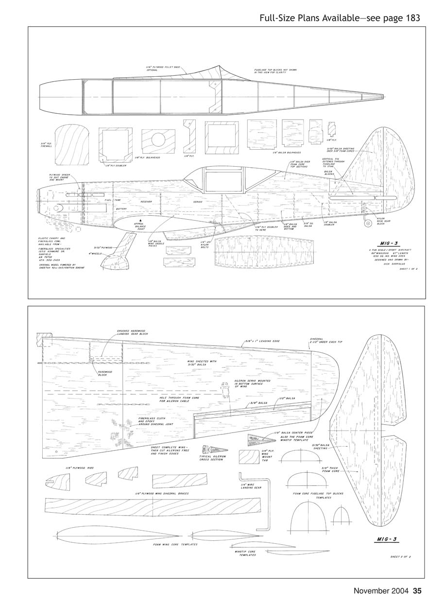
MIG-3
This sheet contains the full-size plan drawings (two sheets) for the MiG-3 model. No additional article narrative text appears on this page.
Transcribed from original scans by AI. Minor OCR errors may remain.

