
Miss-E
by Rodney Helgeland
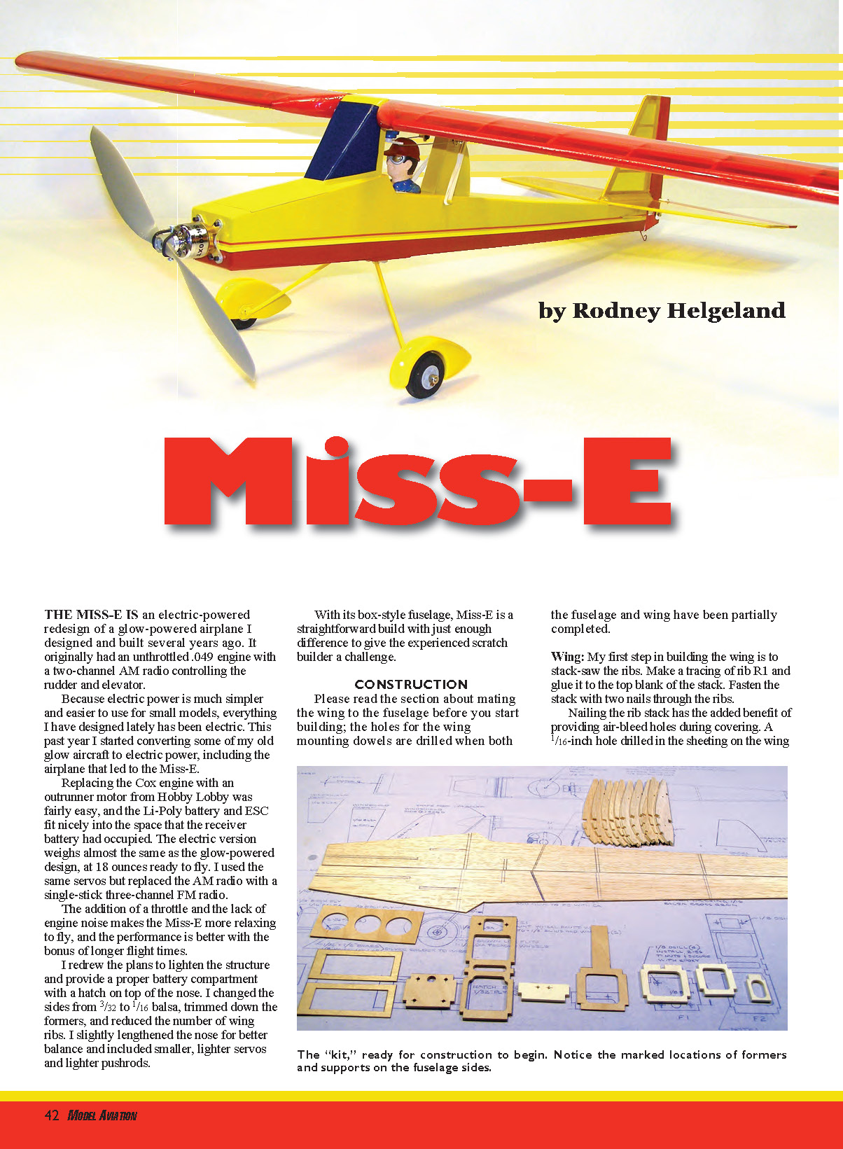
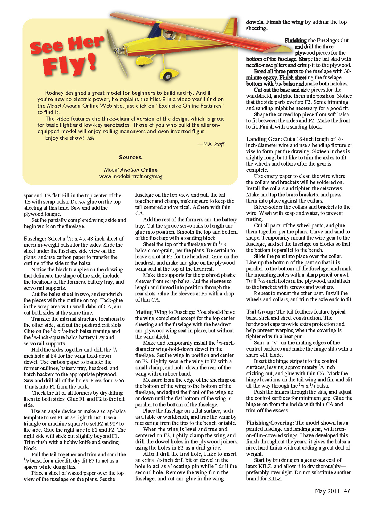
The Miss-E is an electric-powered redesign of a glow-powered airplane I designed and built several years ago. It originally had an unthrottled .049 engine with a two-channel AM radio controlling the rudder and elevator.
Because electric power is much simpler and easier to use for small models, everything I have designed lately has been electric. This past year I started converting some of my old glow aircraft to electric power, including the airplane that led to the Miss-E.
Replacing the Cox engine with an outrunner motor from Hobby Lobby was fairly easy, and the Li-Poly battery and ESC fit nicely into the space that the receiver battery had occupied. The electric version weighs almost the same as the glow-powered design, at 18 ounces ready to fly. I used the same servos but replaced the AM radio with a single-stick three-channel FM radio.
The addition of a throttle and the lack of engine noise makes the Miss-E more relaxing to fly, and the performance is better with the bonus of longer flight times.
I redrew the plans to lighten the structure and provide a proper battery compartment with a hatch on top of the nose. I changed the sides from 3/32 to 1/16 balsa, trimmed down the formers, and reduced the number of wing ribs. I slightly lengthened the nose for better balance and included smaller, lighter servos and lighter pushrods.
With its box-style fuselage, Miss-E is a straightforward build with just enough difference to give the experienced scratch builder a challenge.
CONSTRUCTION
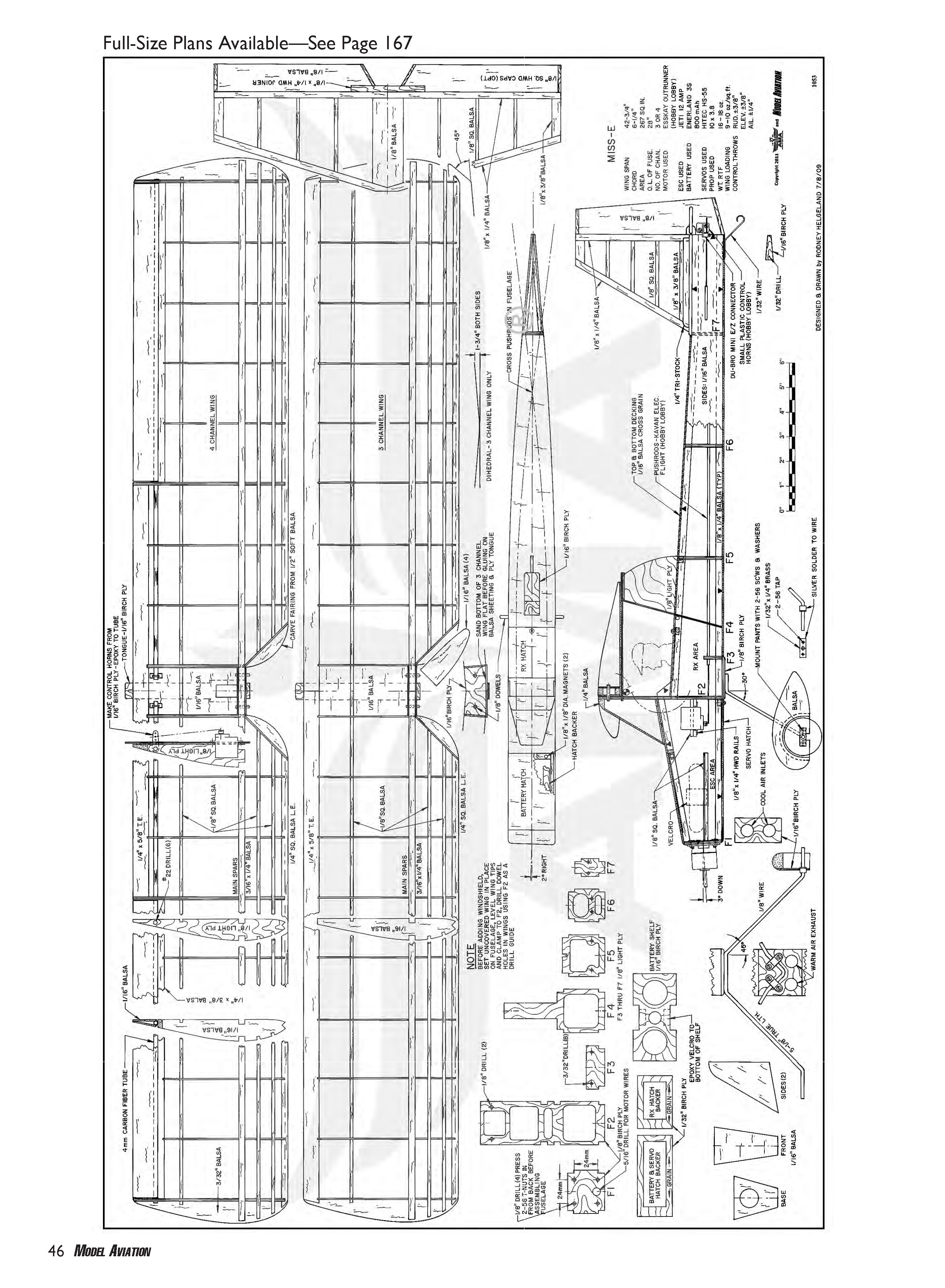
Please read the section about mating the wing to the fuselage before you start building; the holes for the wing mounting dowels are drilled when both the fuselage and wing have been partially completed.
Wing
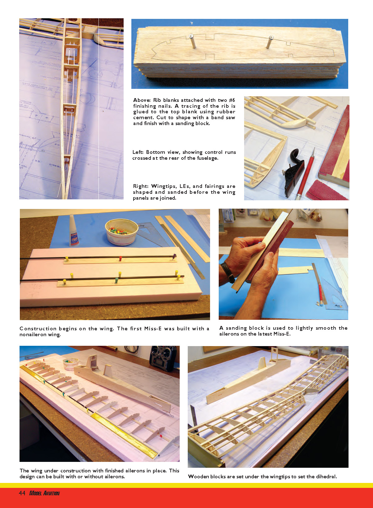
My first step in building the wing is to stack-saw the ribs. Make a tracing of rib R1 and glue it to the top blank of the stack. Fasten the stack with two nails through the ribs. Nailing the rib stack has the added benefit of providing air-bleed holes during covering. A 1/16-inch hole drilled in the sheeting on the wing bottom will relieve pressure buildup from the heat gun when tightening the covering.
After sawing the ribs to shape, finish with a sanding block. Spread the wing section of the plans over the building board and cover with waxed paper. Mark and notch the rib locations on the two trailing-edge (TE) pieces. Pin the bottom spars in place, setting the pins at an angle to leave room to install the top spars without pulling the pins. Use a couple of ribs as spacers to locate and pin the TEs in place.
Form ribs R2 by trimming down a couple of the R1 ribs. Set all ribs in place using a square or triangle to make certain that the ribs are 90° to the spar. Glue the ribs to the bottom spar and the TE with thin CA. Add the top spars and glue in place.
Trim the inner ends of the 1/4-inch square balsa leading edges (LEs) at 45° and glue to the ribs. Cut ribs R3 and sand to a 45° angle where they butt against ribs R2. Glue to R2 and the LE. Add the T-spars and glue in place with thin CA.
I leave the outer ends of the spars long and trim them to 45° after I remove the wing halves from the building board; I find this easier, but you could cut the ends to 45° as you build the wing. Glue a piece of 3/32 balsa sheet to the wing ends and rough-shape the wingtips. Rough out the fairings from soft 1/2 balsa and glue them to ribs R3. Employ a small block plane, hobby knife, and sanding block to finish shaping the wingtips, the LE, and the fairings.
Use a sanding block to carefully shape the inner spar ends and the TEs to a 5° angle. Set the wing panels in place over the wing view on the plans, and block up the tips 1 3/4 inches.
With a machine square or triangle, check the wing panels against the plans to make certain that the wing is straight. Use the sanding block to make necessary adjustments. Adhere the ends of the spars and TEs together with thin CA.
Make the plywood wing joiners. I like to cut a cardboard template to check the fit before I saw the plywood pieces. Glue the joiners into place.
Cut and add the 1/16 balsa bottom sheeting, observing the grain direction shown on the plans. Add the 1/8-inch-square balsa rear spars. Use a sanding block to make the bottom contours of the wing to match the plans. Sand the bottom sheeting flush with the spars.
Make the top center of the TE flat. Fill in the top center of the TE with scrap balsa. Do not glue on the top sheeting at this time. Saw and add the plywood tongue.
Set the partially completed wing aside and begin work on the fuselage.
Full-Size Plans Available—See Page 167
Fuselage
Select a 1/16 x 4 x 48-inch sheet of medium-weight balsa for the sides. Slide the sheet under the fuselage side view on the plans, and use carbon paper to transfer the outline of the side to the balsa. Notice the black triangles on the drawing that delineate the shape of the side; include the locations of the formers, battery tray, and servo rail supports.
Cut the balsa sheet in two, and sandwich the pieces with the outline on top. Tack-glue in the scrap area with small dabs of CA, and cut both sides at the same time. Transfer the internal structure locations to the other side, and cut the pushrod exit slots. Glue on the 1/8 x 1/4-inch balsa framing and the 1/8-inch-square balsa battery tray and servo rail supports.
Hold the sides together and drill the 1/8-inch hole at F4 for the wing hold-down dowel. Use carbon paper to transfer the former outlines, battery tray, headrest, and hatch backers to the appropriate plywood. Saw and drill all of the holes. Press four 2-56 T-nuts into F1 from the back.
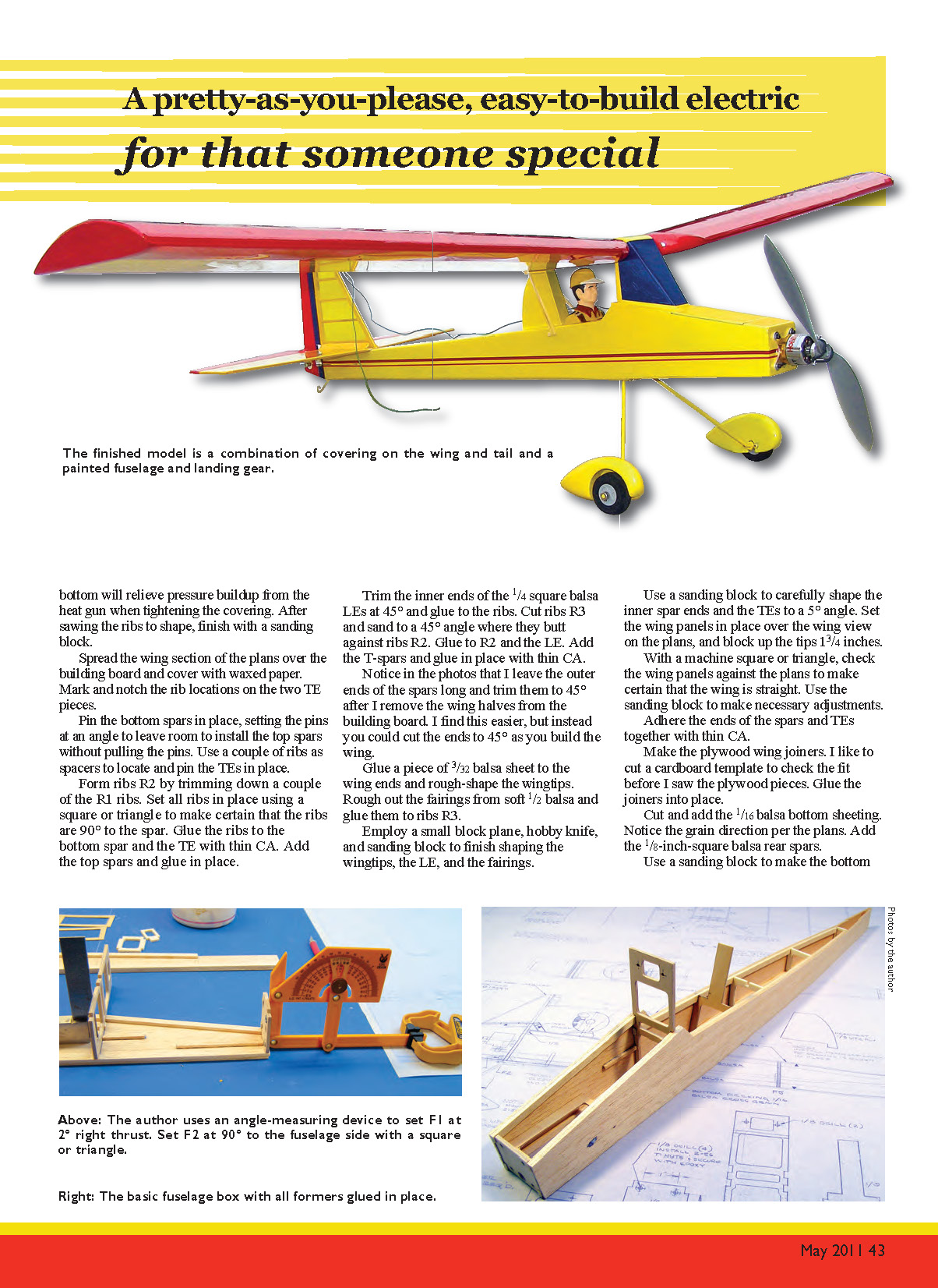
Check the fit of all formers by dry-fitting them to both sides. Glue F1 and F2 to the left side. Use an angle device or make a scrap-balsa template to set F1 at 2° right thrust. Use a triangle or machine square to set F2 at 90° to the side. Glue the right side to F1 and F2. The right side will stick out slightly beyond F1; trim flush with a hobby knife and sanding block.
Pull the tail together and trim and sand the 1/8 balsa for a nice fit; dry-fit F7 to act as a spacer while doing this. Place a sheet of waxed paper over the top view of the fuselage on the plans. Set the fuselage on the top view and pull the tail together and clamp, making sure to keep the tail centered and vertical. Adhere with thin CA.
Add the rest of the formers and the battery tray. Cut the spruce servo rails to length and glue into position. Smooth the top and bottom of the fuselage with a sanding block.
Sheet the top of the fuselage with 1/16 balsa cross-grain, per the plans. Be certain to leave a slot at F5 for the headrest. Glue on the headrest, and make and glue on the plywood wing seat at the top of the headrest.
Make the supports for the pushrod plastic sleeves from scrap balsa. Cut the sleeves to length and thread into position through the rear slots. Glue the sleeves at F5 with a drop of thin CA.
Mating Wing to Fuselage
You should have the wing completed except for the top center sheeting and the fuselage with the headrest and plywood wing seat in place, but without the windshield.
Make and temporarily install the 1/8-inch-diameter wing-hold-down dowel in the fuselage. Set the wing in position and center on F2. Lightly secure the wing to F2 with a small clamp, and hold down the rear of the wing with a rubber band.
Measure from the edge of the sheeting on the bottom of the wing to the bottom of the fuselage, and adjust the front of the wing up or down until the flat bottom of the wing is parallel to the bottom of the fuselage. Place the fuselage on a flat surface, such as a table or workbench, and true the wing by measuring from the tips to the bench or table.
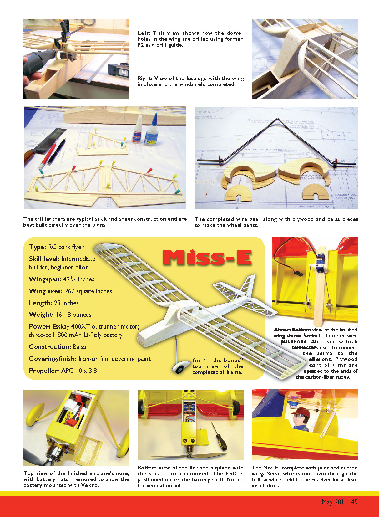
When the wing is level and true and centered on F2, lightly clamp the wing and drill the dowel holes in the plywood joiners, using the holes in F2 as a drill guide. After drilling the first hole, insert an extra 1/8-inch drill bit or dowel in the hole to act as a locating pin while you drill the second hole. Remove the wing from the fuselage, and cut and glue in the wing dowels. Finish the wing by adding the top sheeting.
Finishing the Fuselage
Cut and drill the three plywood pieces for the bottom of the fuselage. Shape the tail skid with needle-nose pliers and crimp it to the plywood. Bond all three parts to the fuselage with 30-minute epoxy. Finish sheeting the fuselage bottom with 1/16 balsa and make both hatches.
Cut out the base and side pieces for the windshield, and glue them into position. Notice that the side parts overlap F2. Some trimming and sanding might be necessary for a good fit. Shape the curved top piece from soft balsa to fit between the sides and F2. Make the front to fit. Finish with a sanding block.
Landing Gear
Cut a 16-inch length of 1/8-inch-diameter wire and use a bending fixture or vise to form per the drawing. Sixteen inches is slightly long, but I like to trim the axles to fit the wheels and collars after the gear is complete.
Use emery paper to clean the wire where the collars and brackets will be soldered on. Install the collars and tighten the setscrews. Make and tap the brass brackets, and press them into place against the collars. Silver-solder the collars and brackets to the wire. Wash with soap and water to prevent rusting.
Cut all parts of the wheel pants, and glue them together per the plans. Carve and sand to shape. Temporarily mount the wire gear to the fuselage, and set the fuselage on blocks so that the bottom is parallel to the bench.
Slide the pant into place over the collar. Line up the bottom of the pant so that it is parallel to the bottom of the fuselage, and mark the mounting holes with a sharp pencil or awl. Drill 3/32-inch holes in the plywood, and attach to the bracket with screws and washers. Repeat to mount the other pant. Install the wheels and collars, and trim the axle ends to fit.
Tail Group
The tail feathers feature typical balsa stick-and-sheet construction. The hardwood caps provide extra protection and help prevent warping when the covering is tightened with a heat gun.
Sand a "V" on the mating edges of the control surfaces and make the hinge slits with a sharp #11 blade. Insert the hinge strips into the control surfaces, leaving approximately 3/8 inch sticking out, and glue with thin CA. Mark the hinge locations on the tailplane and fin, and slit all the way through the 1/8 x 1/4 balsa.
Push the hinges through the slits, and glue the control surfaces for minimum gap. Glue the hinges on from the inside with thin CA and trim off the excess.
Finishing/Covering
The model shown has a painted fuselage and landing gear, with iron-on film-covered wings and tail. I have developed this finish throughout the years; it gives the balsa a nice, hard finish without adding a great deal of weight.
Start by brushing on a generous coat of latex KILZ, and allow it to dry thoroughly—preferably overnight. Do not substitute another brand for KILZ. Lightly finger-sand with 150-grit paper at an angle to the wood grain. The idea is to remove most of the primer but leave the balsa pores filled. You will get a smoother finish each time you repeat this step, but remember that paint adds weight. KILZ fills the pores and also seems to harden the balsa.
Sand the last coat of primer smooth with fine sandpaper, and wipe with a tack rag. Install the wing hold-down dowel and glue with thin CA. Spray on a coat of gray sandable primer. You can try sanding the primer with 400-grit paper, but be extremely careful not to sand through the primer. Breaking through that surface can cause bubbling in the final coat.
I spray the color coats directly over the unsanded primer. Although instructions on the paint can are to sand the primer, I can't tell the difference in the final color coat between sanding and not sanding.
The fuselage and landing gear were painted with Rust-Oleum Farm Equipment spray in John Deere Yellow (item 7443-830). I covered the wing and tail feathers with yellow and dark-red Lightweight Transparent Polycover from Hobby Lobby.
Assembly
Remove the covering from the top of the stabilizer where the fin attaches, and glue the fin in place. Use a triangle or machine square to keep the fin 90° to the stabilizer while the adhesive dries. Add the 1/4-inch triangle stock bracing, and cover to match. Dry-fit the tail group to the fuselage, and mark the locations and angles of the control horns. Screw both control horns into position.
Remove the covering from the bottom of the stabilizer where it mates to the fuselage and attach with 30-minute epoxy. Use a straightedge placed along the fin and headrest to align the tail group. Pin the tail group in place and allow the epoxy to set.
Screw the landing gear in place with the nylon landing gear straps. If you snug the screws holding the straps, the wire will be allowed to slide a little on hard landings, reducing the stress on the gear and fuselage. Mount the servos and finish the control runs. Set the control throws at approximately 3/8 inch either way for the first flights.
Install the motor and electronics, and make all of the electrical connections. Attach the propeller adapter and propeller. Rubber-band the wing in place, and set the battery on the battery tray. Balance the model by placing your fingertips under the main spar, near the ends of the wing. Slide the battery back and forth until Miss-E hangs level or slightly nose-down. Mine balanced perfectly with the battery pushed all the way forward.
Flying
Pick a calm day for the first flight, if possible. The day I made mine, the wind was blowing 10–15 mph. Although I don't recommend those conditions, it was the last day a visiting friend could take flying pictures.
The Miss-E bounced around the sky but proved to have enough power and control authority to fly in windy conditions. A not-so-graceful landing, when a gust caught the model, proved the integrity of the design, and the airplane came through undamaged.
If you launch the model by hand, do so straight ahead at approximately one-third to half throttle. As do all lightly loaded aircraft with flat-bottomed wings, Miss-E will climb under power. The 4° downthrust helps, but you can never totally cure the tendency to climb under advancing throttle. I like to trim the airplane to fly hands-off on a calm day at close to half throttle.
Miss-E is capable of mild aerobatics such as loops, but it was designed for relaxed cruising around the flying field. With its light weight, fairly large frontal area, and big propeller, this model does not glide well with the power off. It's best to keep the propeller turning and cut the power at touchdown.
I hope you enjoy building and flying Miss-E as much as I have.
Rodney Helgeland [email protected]
- Type: RC park flyer
- Skill level: Intermediate builder; beginner pilot
- Wingspan: 42 3/4 inches
- Wing area: 267 square inches
- Length: 28 inches
- Weight: 16–18 ounces
- Power: Esskay 400XT outrunner motor; three-cell, 800 mAh Li-Poly battery
- Construction: Balsa
- Covering/finish: Iron-on film covering, paint
- Propeller: APC 10 x 3.8
Sources
- KILZ — (866) 325-3552 — www.masterchem.com
- Rust-Oleum — (800) 323-3584 — www.rustoleum.com
- Hobby Lobby — (866) 512-1444 — www.hobby-lobby.com
Transcribed from original scans by AI. Minor OCR errors may remain.

