
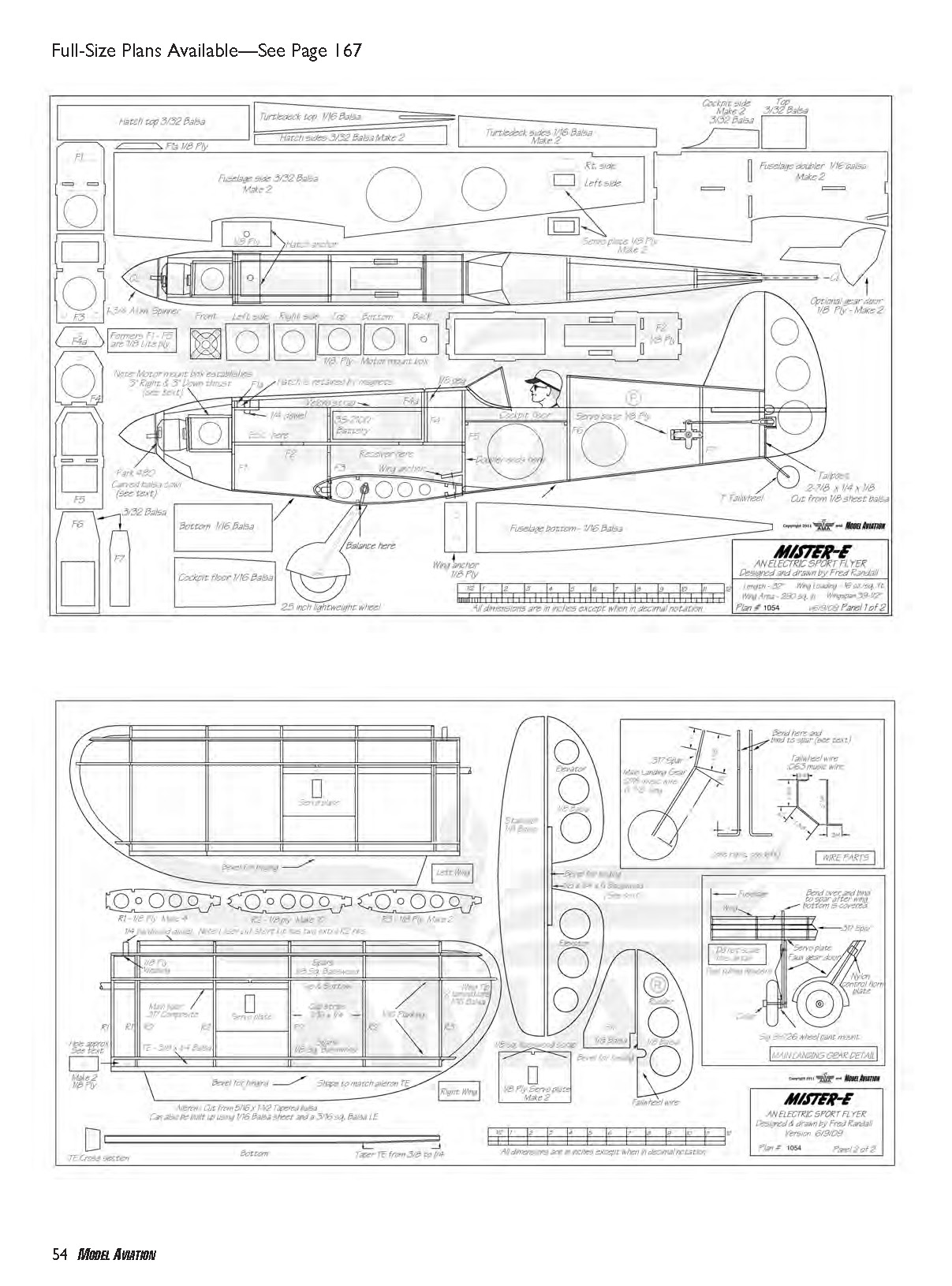
Mister-E
by Fred Randall
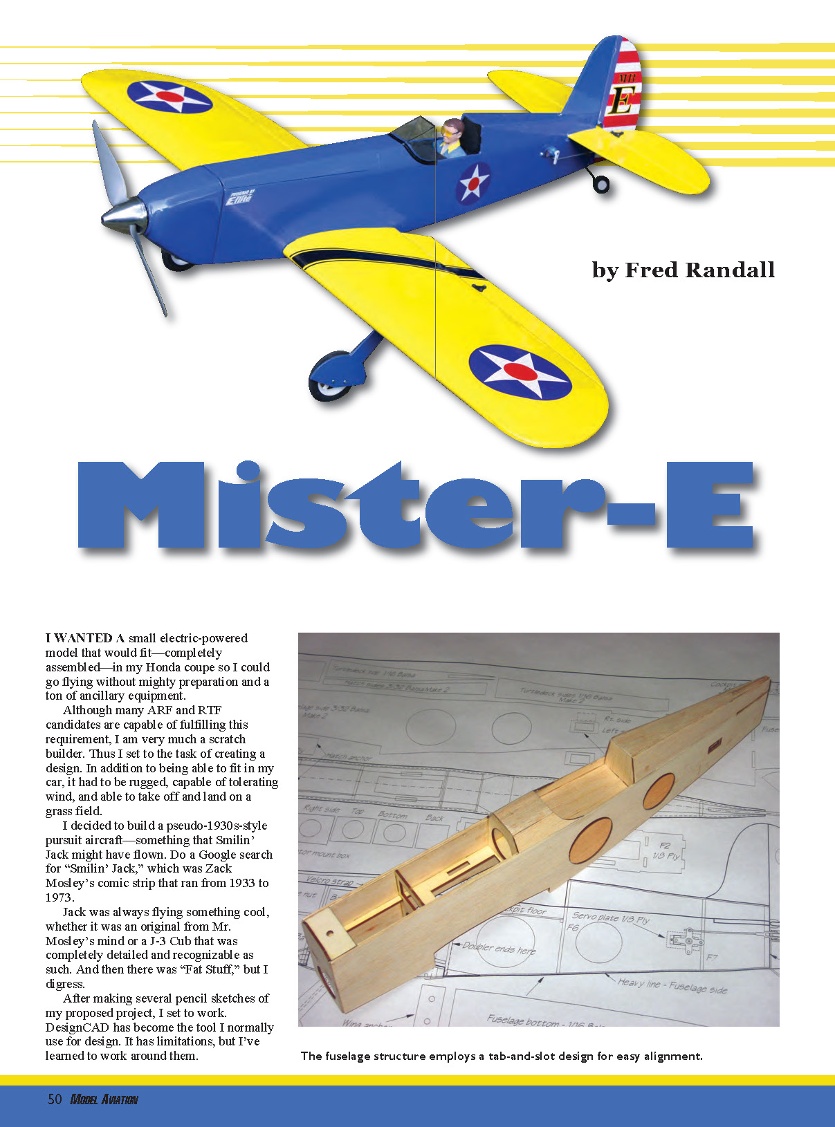
I wanted a small electric-powered model that would fit—completely assembled—in my Honda coupe so I could go flying without mighty preparation and a ton of ancillary equipment.
Although many ARF and RTF candidates can fulfill this requirement, I am very much a scratch builder. Thus I set to the task of creating a design. In addition to being able to fit in my car, it had to be rugged, capable of tolerating wind, and able to take off and land on a grass field.
I decided to build a pseudo-1930s-style pursuit aircraft—something that Smilin’ Jack might have flown. Smilin’ Jack was Zack Mosley’s comic strip that ran from 1933 to 1973, and he often flew cool aircraft, whether original designs or clearly detailed J-3 Cubs.
After making several pencil sketches, I set to work. DesignCAD has become the tool I normally use for design. It has limitations, but I’ve learned to work around them. I enjoy using DesignCAD to draw scale motors, servos, and pilots. Better still, I can make patterns to have my model parts laser-cut at Creative Hobbies, which is only four miles from my house.
Another bonus is that Creative Hobbies sells a laser-cut kit for this aircraft, including most plywood and balsa parts. The only unusual item I used in construction was a .317-inch fiberglass-composite main spar. You can buy inexpensive fiberglass-composite tubing from Goodwinds LLC and Kite Studio, which have no minimum-order requirements. Their contact information is in the Sources listing.
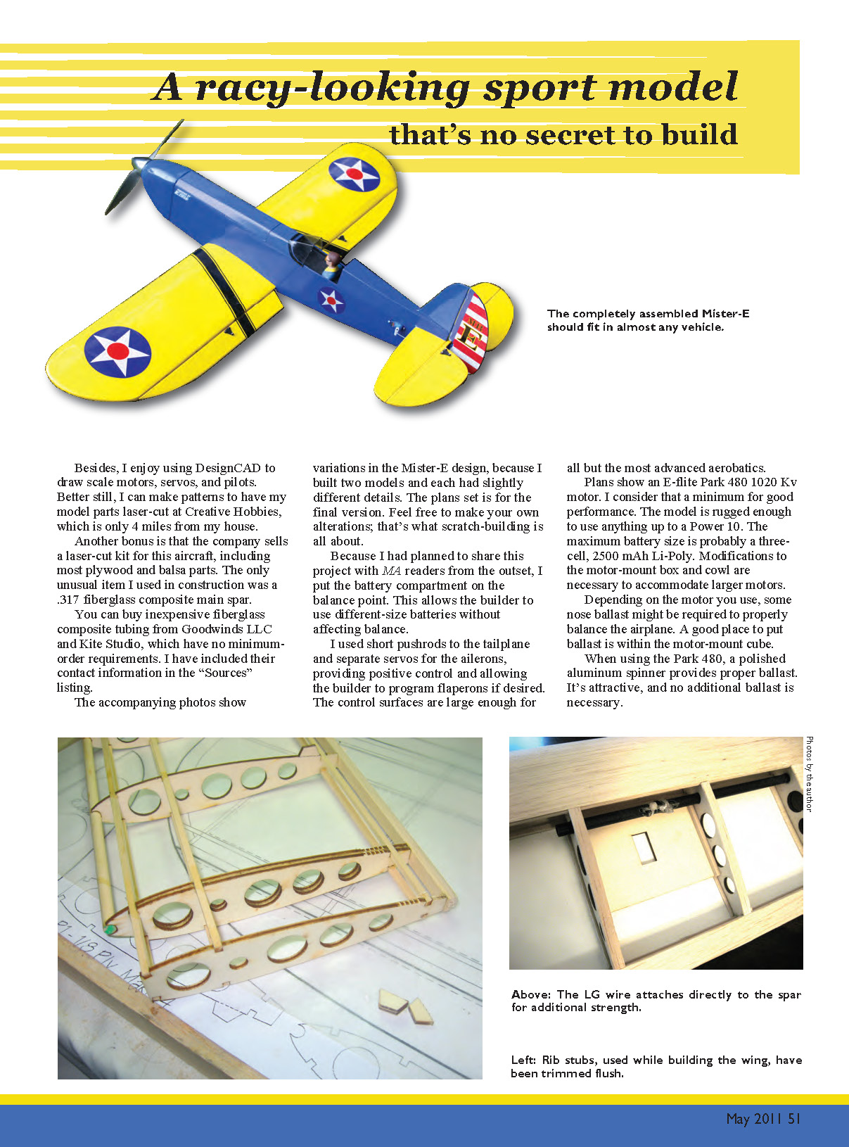
The accompanying photos show variations in the Mister-E design, because I built two models and each had slightly different details. The plans set is for the final version; feel free to make your own alterations—that's what scratch-building is all about.
Because I planned to share this project with MA readers, I put the battery compartment on the balance point. This allows the builder to use different-size batteries without affecting balance.
I used short pushrods to the tailplane and separate servos for the ailerons, providing positive control and allowing the builder to program flaperons if desired. The control surfaces are large enough for all but the most advanced aerobatics.
Plans show an E-flite Park 480 outrunner (1020 Kv). I consider that a minimum for good performance. The model is rugged enough to use anything up to a Power 10. The maximum battery size is probably a three-cell, 2500 mAh Li-Poly. Modifications to the motor-mount box and cowl are necessary to accommodate larger motors.
Depending on the motor you use, some nose ballast might be required to properly balance the airplane. A good place to put ballast is within the motor-mount cube. When using the Park 480, a polished aluminum spinner provides proper ballast—it's attractive, and no additional ballast is necessary.
Before you begin, bear in mind that the Mister-E is not a park flyer (unless the park is huge). It flies fast and needs room. It is designed to fly from a club field or equivalent space.
Specifications
- Type: RC electric sport/aerobatic
- Skill level: Intermediate builder; intermediate pilot
- Wingspan: 39-1/2 inches
- Wing area: 290 square inches
- Length: 32 inches
- Weight: 31 ounces
- Power: E-flite Park 480 outrunner; three-cell, 2100–2500 mAh Li-Poly battery
- Construction: Balsa
- Covering/finish: LighTex iron-on film
- Propeller: APC 11 x 6
CONSTRUCTION
Use medium CA unless otherwise noted. If you are not building from the laser-cut kit, fabricate all parts before you start construction. Once you have the parts at hand, assembly goes rapidly.
Fuselage
The fuselage is based on a snap-together box featuring a tab-and-slot design for automatic alignment. Snap together F1, F2, F3, F4, F5, and the wing anchor plate, and then snap on the 1/16-inch balsa fuselage doublers. Apply thin CA to all joints for permanent assembly.
Mark the inside of the 3/32-inch balsa sides with the locations of F6 and F7. Test-fit the sides for alignment, being careful to ensure that the aft ends of both sides will mate properly when they are joined later.
Adhere two 1/8-inch plywood servo-reinforcement pieces inside the fuselage sides.
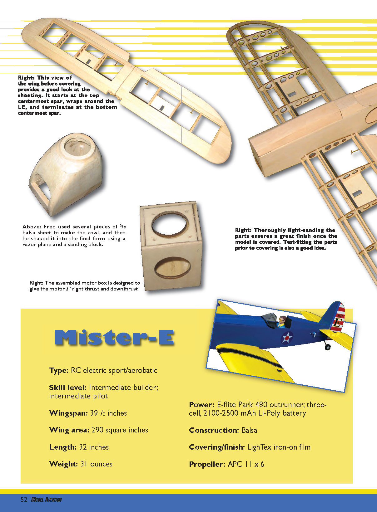
Carefully assemble the six-piece motor-mount box using CA. All parts are designed to give the motor 3° right thrust and 3° downthrust, so assemble the box correctly. Adhere the box to F1 using epoxy, ensuring it is offset as indicated on the fuselage drawing. This sets the propeller shaft on the model's centerline.
There is a hole in the back of the box. You can use a small screw or add more epoxy in it to ensure the box is permanently attached to the firewall. Apply epoxy fillets to the inside joints of the motor-mount box for strength.
Fashion a tail post as the plans show; it extends up to the top of the turtledeck. Pull the fuselage sides together and use T-pins to temporarily sandwich the tail post. Using the fuselage top view as a guide, ensure the tail post is centered and square with the sides. When satisfied, apply a couple drops of thin CA to the joint.
Position F6 and F7 at their stations within the fuselage. When aligned, use thin CA to permanently install them. Apply more CA to the tail post/fuselage side joints.
Fabricating the hatch requires care to ensure a good fit. Pin F1a and F4a against F1 and F4 respectively, flush with their counterparts. Patterns for the 3/32-inch balsa hatch sides are slightly oversized. Position them on the fuselage over F1a and F4a. There will be a slight twist in the hatch sides when attached to the formers. The sides should overlap F1a and F4a and be flush with the front of F1.
Carefully sand the bottoms of the hatch sides so they mate flush with the fuselage along their lengths. Use CA to adhere the hatch sides to F1a and F4a only. The twist necessitates holding the sides in place long enough for the CA to set.
Remove the pins from F1a and F4a. Lift the hatch assembly off the fuselage and, using a long sanding block, sand the tops of the hatch sides so they are flush with the tops of the formers. The hatch top, which is also slightly oversized, should lay flat on the top of the hatch assembly. Use CA to adhere the hatch top in place, and block-sand it so it mates with the hatch sides along its length. Cement in the hatch locating dowels. They should align the hatch and enable a small rare-earth magnet, or magnets, to secure the hatch at the front.
Continue planking the fuselage, including the cockpit surround and the turtledeck. Install the 1/16-inch cockpit floor and the fuselage bottom from the wing TE to the tail post. Leave the bottom open ahead of the wing LE at this time. Note that the cockpit forward area is open to the fuselage interior, providing an exit for cooling air.
This completes the initial fuselage assembly.
Wing
As a preliminary operation, cement together the 1/16-inch balsa wingtip laminations using thin CA. They should be cross-grained to each other for maximum strength.
Secure the right-wing plan to your building board. After cutting a length of 1/8-inch square basswood to size, use T-pins to attach it in position as the centermost bottom spar. Use this spar as a reference for building the entire wing.
Using a small square to keep it vertical, position an R1 root rib in place and use CA to adhere it to the spar. The break-off tab at the aft bottom of the rib should lay flat on the plans, and the rib should be held in alignment until the CA sets. Follow suit with the rest of the ribs. Ensure the bottoms of all break-off tabs are flat on the plans.
Cut a piece of 1/4-inch hardwood dowel for the LE, mount it to the front of the ribs, and secure it with CA. Cut all upper spars to length and glue them in place.
Using a 9/16-inch-high piece of scrap balsa as a support, attach the wingtip extending straight outward from the LE and TE, bisecting the airfoil. Cut a length of 3/8 x 1/4-inch balsa to form the wing TE. Shape it to match the drawing using a razor plane and a sanding block. Remove the partially completed wing from the building board and adhere the TE in position. Install the remaining 1/8-inch square spars.
Lay the completed wing frame on the building board; all break-off stubs should be flat against it.
Remove the right-wing assembly and secure the left-wing plan to the board. Be careful: it is easy to end up building two right wings or two left wings. Follow the same instructions to build the left wing.
Next is the servo-plate installation. Cut several 1/8-inch square basswood sticks to length and adhere them to the servo plates using CA as the plans show. These provide additional surface for bonding the plates to the ribs. Use CA to secure the servo plates to the wings, as close to flush with the bottoms of the ribs as possible.
Fit the 1/8-inch light-plywood webbing that provides a mount for the front wing pegs. These measure approximately 1/2 x 1-3/32 inches but should be cut slightly oversize and sanded so they are a push fit between the R1 ribs and the front upper and lower 1/8-inch square spars on each wing. Apply CA to the webbing to hold it in place—don't spare glue here.
Plank both wings with 1/16-inch balsa, as shown on the plans. The front planking starts at the top centermost spar, wraps around the LE, and terminates at the bottom centermost spar. If you use thin CA to bond a 4-inch-wide sheet and a 3-inch sheet, you can avoid buying wing skins—match the sheets for hardness. One 36-inch sheet of each width will cover both LEs.
Using Windex facilitates making the sharp bend around the LE. Liberally spray both sides of the balsa and wait at least five minutes before attempting the bend.
Recheck the wings, ensuring the break-off stubs are still flat. If everything checks out, break off the stubs and sand the area smooth.
I chose to entirely plank both sides of the wingtips. It's an option; planked tips work well for those less confident with covering. The remaining wing planking and capstrips require one sheet of 1/16 x 4 x 36-inch balsa.
Wing Fitment
Cut and predrill the composite spar (.317-inch). The holes must be properly positioned at both ends. I used a piece of pine strapping with a finishing nail driven vertically into it, making a simple fixture to ensure the second hole is parallel to the first when positioned in my drill press.
When you have completed the planking, use the .317 composite spar to assemble the wings. Do not permanently join them at this time. Hold the root ribs together tightly using masking tape on the bottom of the wings.
Position the wings in the fuselage wing-mount recess. If necessary, remove material from the balsa TEs so the wings seat properly.
Looking through the peg holes in F3, use a pencil to mark the position of the dowels on the webbing installed in the wings. This is why the forward fuselage planking was not installed previously.
Remove the wings from the fuselage and drill the webbing for the 1/4 x 1/2-inch wing-mounting dowels. Cut the dowels to size and slightly bevel the fronts. Use CA to adhere the dowels to the webbing. They should extend approximately 3/8 inch from the front of the mounting plate.
When the CA has set, test-fit the wings. If done correctly, they should be seated properly, with the pegs inserted into the holes in F3. Now you can install the 1/16-inch balsa fuselage bottom piece.
Carefully measure the location of the holes in the rear mounting plate. Mark the corresponding hole locations on the joined wings. Drill them out with a 1/16-inch and then a 1/4-inch drill bit. Ensure the path to the rear wing-anchor-bolt locations is clear. These holes should allow easy passage of the wing mounting bolts; the 1/8-inch light-plywood reinforcements have smaller holes and will be applied next.
Ailerons
There are two options for making the ailerons: build up using a 3/16-inch square LE and 1/16-inch balsa sheet, or shape them from 5/16 x 1-1/2-inch tapered balsa aileron stock. Either method is acceptable; shape the aileron LE to mate with its respective wing TE. I opted to use the shaped stock.
Empennage
First join the elevator halves. I prefer not to use joiner wires because they can be flexible enough to allow flutter at high speed. I used a 5-inch piece of 1/8 x 1/4-inch basswood as a joiner. If you don't have the correct size, adhere two pieces of 1/8-inch square basswood spar stock together.
Secure the elevator plan to the building board. Secure the elevator halves and the joiner to the plans to ensure proper span and alignment. Shape the joiner's LE for hinging before you adhere it with medium CA to the elevator halves.
Test-fit the fin and stabilizer. Cut the tail post away from the stabilizer slot, then find the centerline of the 1/8-inch balsa stabilizer and insert it into the fuselage. Ensure it is straight and the TE is flush with the back of the fuselage. Shim or trim the slot as necessary to align the stabilizer.
Insert the fin into its slot. It should be vertical and its bottom should seat against the stabilizer. After checking alignment, remove the fin and stabilizer until after you have covered the model.
Landing Gear, Etc.
Remaining tasks include beveling and hinging the control surfaces, covering and installing the empennage, and installing equipment. The landing-gear (LG) mounting needs clarification.
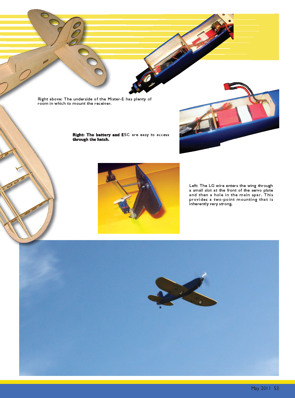
The procedure described results in a wide-track LG that has proven nearly unbreakable. The main composite spar is used as an inner anchor for the LG wire. Before installation, cut the spar to length and drill 1/8-inch holes in both ends. The holes must be parallel and positioned directly over the small slot at the front of the servo plates—use the plans as a guide.
Bend the LG wire to shape using the diagram on the plans. Do not make the bend where the wire attaches to the spar, but mark the wire where the bend will be made.
The LG wire enters the wing through the small slot at the front of the servo plate and then through a hole in the main spar. This provides a two-point mounting that is inherently very strong.
Proceed as follows:
- Cover both wing bottoms (only), and then clear the small slot in the servo plate.
- Insert the predrilled composite main spar into position in one wing, with the drilled hole directly above the slot.
- Insert the LG wire through the slot and through the hole in the spar. Push the wire through far enough to provide easy access to the top so you can make the 90° bend.
- Make the bend at the marked position so it is parallel to the wheel-mount bend at the bottom.
- Lower the LG wire until the bend rests on the spar. Use two small tie-wraps to secure the LG wire to the spar. Ensure the mounted wheel will track straight; small tracking errors can be compensated for at the spar.
- Mix 30-minute epoxy and use it to join the wings. Employ clamps and masking tape while the epoxy cures.
- Install the LG wire on the remaining side using the same procedure. Secure the LG wire to the spar with 30-minute epoxy.
Make small holes in the wing planking adjacent to the root ribs for passage of the servo wires. Install the wing servos and run the wires. Now you can cover the tops of both wings.
The faux gear doors are optional, but they add much to the appearance. The doors are attached using Sig wheel pant mounts (item SIGSH726). Spacers cut from fuel tubing provide a fore-and-aft shock mount.
The top part of the gear doors is secured using backing plates from a pair of small control horns; fuel-tubing spacers are used here as well. This arrangement allows the LG wire to flex considerably without stressing the 1/8-inch plywood gear doors.
I sprayed the inside of the gear doors with Flat Black Krylon before covering the outside with LighTex that matches the fuselage color.
Cowl
The balsa cowl must accommodate the motor you use, so I haven't provided fixed dimensions. See the article "Cowl Making 101" in the November 2008 MA for my method.
My cowl was produced from several pieces of 3/8-inch balsa sheet. First I used a hole saw to make a balsa disc to fit the spinner I used (a 1-3/4-inch aluminum unit), then cut a large-enough hole in the disc to accommodate a small drum sander. I opened the resulting balsa "doughnut" slightly larger than the motor diameter; for the Park 480 that is slightly bigger than 1-3/8 inches.
I cut two pieces of 3/8-inch sheet to form the sides of the cowl and another to form the top. I adhered those pieces to the cowl ring after carefully shaping them to form a flush fit against the ring and the firewall. A short bottom piece extends from the cowl ring halfway to the firewall. The gap provides cooling-air intake for the ESC and battery.
I used a razor plane and sanding block to shape the assembly, applied balsa filler to gaps, and finish-sanded with 400-grit paper. I applied several coats of Top Flite white primer, wet-sanded, then several coats of Krylon True Blue—the color matches the covering almost exactly.
Finishing
I used LighTex blue for the fuselage, fin, and rudder, and cadmium yellow for the wings, stabilizer, and elevator.
I applied homemade water-slide decals to the rudder. Along with 13 alternating red-and-white stripes, it is emblazoned with the model name: "MR E."
Early World War II insignia was applied to the wings and fuselage, and a black multi-stripe "V" pattern was applied to the top side of the wings.
Hinging was accomplished using CA-type cloth hinges—full-sized on the wings and half-width on the empennage.
Setup
Accurate parts alignment is crucial, particularly the wing/stabilizer angle of incidence. If you don't have an incidence gauge, try to borrow one. The acceptable angle of incidence is between 0° and 1/4°.
Ensure the stabilizer, elevators, fin, and rudder are not warped. If they are, rectify with clamps and a heat gun.
Proper balance is important; the balance point should be 2-2/3 inches behind the wing LE. Make first flights with the balance nearer to the 2-inch mark.
Flying
Mister-E has large control surfaces and a short tail-moment arm, making it extraordinarily sensitive to control inputs. Limit initial deflection to 1/4 inch on the ailerons and elevator (each direction). The rudder is equally sensitive—limit deflection to 3/8 inch on both sides until you are used to flying the airplane.
If you have a computer radio, program approximately 40% exponential. High rates can be double the stated low-rate deflection, but exponential programming is recommended. It is also good to program flaperons if your transmitter is capable.
This model is better suited for an experienced pilot. A light touch on the sticks is best when learning to fly Mister-E.
Takeoff from a grass field requires full up-elevator until flying speed is achieved, usually in 20 feet or fewer. The model tends to float in on landing; make approaches with some power, set up a glide slope, and apply a bit of up-elevator on touchdown to keep the tail planted.
Mister-E is a joy to fly once you get comfortable with it. With greater control deflection it is capable of tight loops and a dizzying roll rate.
Have fun building and flying Mister-E. It's great to have a unique model to bring to the field.
Keep 'em flying! Fred Randall [email protected]
Sources
- Creative Hobbies
(508) 473-8259 www.creativehobbies.net
- Goodwinds LLC
(206) 632-6151 www.goodwinds.com
- Kite Studio
(610) 395-3560 www.kitebuilder.com
- Balsa and light plywood: Balsa USA
(906) 863-6421 www.balsausa.com
Transcribed from original scans by AI. Minor OCR errors may remain.

