
Moffett Redux - 2003/10
William Langenberg
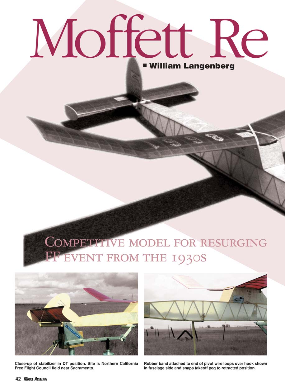
Competitive model for resurging FF event from the 1930s
Rear Admiral William A. Moffett headed the US Navy’s Bureau of Aeronautics from its inception in 1921 until his death in 1933. His primary duty during that assignment was to effectively integrate fledgling naval aviation into fleet operations.
Former skipper of the cruiser USS Chester and the battleship USS Mississippi, Moffett was surprisingly not a qualified naval aviator. However, during the 1920s and 1930s he became one of the Navy’s best-known and most articulate naval-aviation supporters.
Perhaps most closely associated in the public’s mind with rigid airships, commonly known as dirigibles, Moffett was killed in the crash of the USS Akron off the New Jersey coast in April 1933.
Because of his support for aviation, an international Free Flight model-airplane competition bearing his name began in the 1930s. It was held as an annual event at the AMA Nationals and featured teams of six candidates from the US, Canada, England, Australia, and New Zealand. Participants for the latter three nations were frequently represented by American proxy fliers.
The Moffett competition languished after World War II, but it was reincarnated as an official National Free Flight Society (NFFS) event in 1992. The simple rules are:
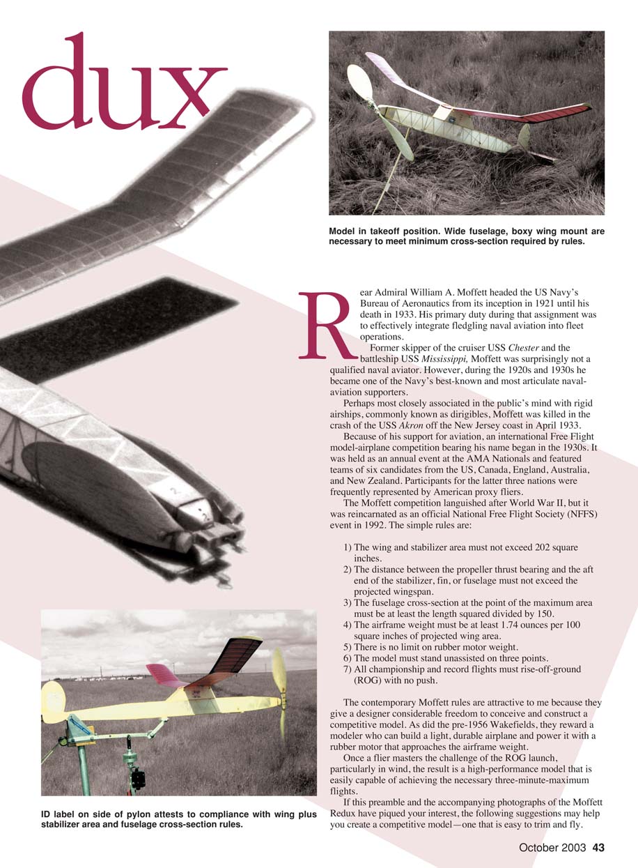
- The wing and stabilizer area must not exceed 202 square inches.
- The distance between the propeller thrust bearing and the aft end of the stabilizer, fin, or fuselage must not exceed the projected wingspan.
- The fuselage cross-section at the point of the maximum area must be at least the length squared divided by 150.
- The airframe weight must be at least 1.74 ounces per 100 square inches of projected wing area.
- There is no limit on rubber motor weight.
- The model must stand unassisted on three points.
- All championship and record flights must rise-off-ground (ROG) with no push.
The contemporary Moffett rules are attractive to me because they give a designer considerable freedom to conceive and construct a competitive model. As did the pre-1956 Wakefields, they reward a modeler who can build a light, durable airplane and power it with a rubber motor that approaches the airframe weight. Once a flier masters the challenge of the ROG launch, particularly in wind, the result is a high-performance model that is easily capable of achieving the necessary three-minute maximum flights.
If this preamble and the accompanying photographs of the Moffett Redux have piqued your interest, the following suggestions may help you create a competitive model—one that is easy to trim and fly.
CONSTRUCTION
Stabilizer
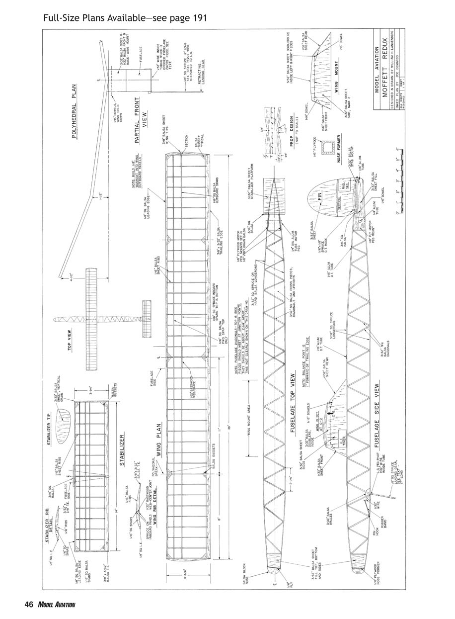
Begin with the stabilizer so that it can be covered, doped, and cured before you attempt any test flights. Use contest-grade balsa to keep weight down. During assembly, pack up the front of the trailing edge to conform with the airfoil as shown on the plans. Assemble the parts on a flat surface, adding the spruce dethermalizer (DT) hooks as the last operation.
Carefully sand the stabilizer and cover it with tissue. Add the tip plates before the tissue is water-sprayed, and give the entire structure at least three coats of thinned dope. I normally prefer nitrate to butyrate dope because it appears more resistant to moisture in the air. The completed stabilizer should be free of warps. The finished weight should not exceed 8 grams, including the attached fin.
Wing
The wing is next in the construction sequence. It is straightforward and should present few building problems. Select the wood with care; the structure should be kept as light as possible. Ribs are cut from 1/16-inch quarter-grain stock. The trailing edge is made from similar 1/8-inch sheet balsa.
As on the stabilizer, pack up the front of the trailing edge to conform to the proper airfoil shape. Using liberal amounts of glue on all joints, join the wing panels to the polyhedral dimensions indicated. Do not cement spars to the ribs at the polyhedral breaks until the panels are blocked up to the proper angles.
Install the center basswood gusset and triangular balsa reinforcements as shown. Carve the wingtips from soft 3/8-inch sheet balsa, then cautiously sand the entire completed structure to facilitate an attractive covering job. Cover the wing with good-quality tissue. As with the stabilizer, apply at least three coats of nitrate dope. Set the wing aside and allow it to cure thoroughly.
Each outboard wing panel should have 1/4 inch of washout, which should occur naturally as the doped covering cures. The finished weight ought not to exceed 19 grams. Remember that the maximum projected area of the wing and stabilizer is 202 square inches. Trim off the wing trailing edge to meet this parameter if necessary.
Fin
Cut the fin from soft 3/32-inch sheet balsa to the outline shown on the plans. Carve and sand it to a streamlined shape to give a left turn in the glide. Glue it to the top of the doubled center stabilizer rib, ensuring that it is perpendicular.
Fuselage
Select four hard 3/32 x 3/32-inch balsa strips for the longerons. I used spruce longerons for durability, but your preference may vary. Build two fuselage sides on the plans, ensuring that the diagonals do not run the same direction on both sides. Add the 3/32-inch sheet fillers for the rear rubber peg and nose area.
When joining the fuselage sides, tack-glue 3/32 x 3/32-inch crosspieces to the longerons approximately every eight inches to set up the fuselage shape throughout its square section. Insert the 3/32 x 3/32-inch diagonals, proceeding equally along the top and bottom. You can remove the tack-glued crosspieces as diagonals take their places. If you prefer, a simple fixture can be constructed to facilitate fuselage assembly.
Add the 3/32-inch sheet balsa fillers at the front top and bottom of the fuselage, then glue the remainder of the diagonals in place. Insert the 1/8-inch sheet balsa reinforcing pieces, with their 1/8-inch plywood inserts, inside the rear motor-peg section as indicated on the plans.
Carve and sand 3/32-inch right thrust into the fuselage nose. Cut out the 1/16-inch plywood nose former and glue it accurately in place. Sand the entire fuselage smooth, and cover it with Polyspan or equivalent. For durability you may want to double-cover the fuselage bottom, cross-graining the Polyspan.
Cut out the wing mounts and stabilizer platform and glue them to the fuselage as shown. Then add the 1/16-inch aluminum tubing DT line guides and the 1/16-inch-diameter dowel rubber hooks for the wing attachment and stabilizer DT system.
The mini-timer shown in the photographs weighs 6 grams. If you elect to use one, position it on the wing mount; if it is mounted on the fuselage side, the unwinding rubber motor can disrupt its accuracy.
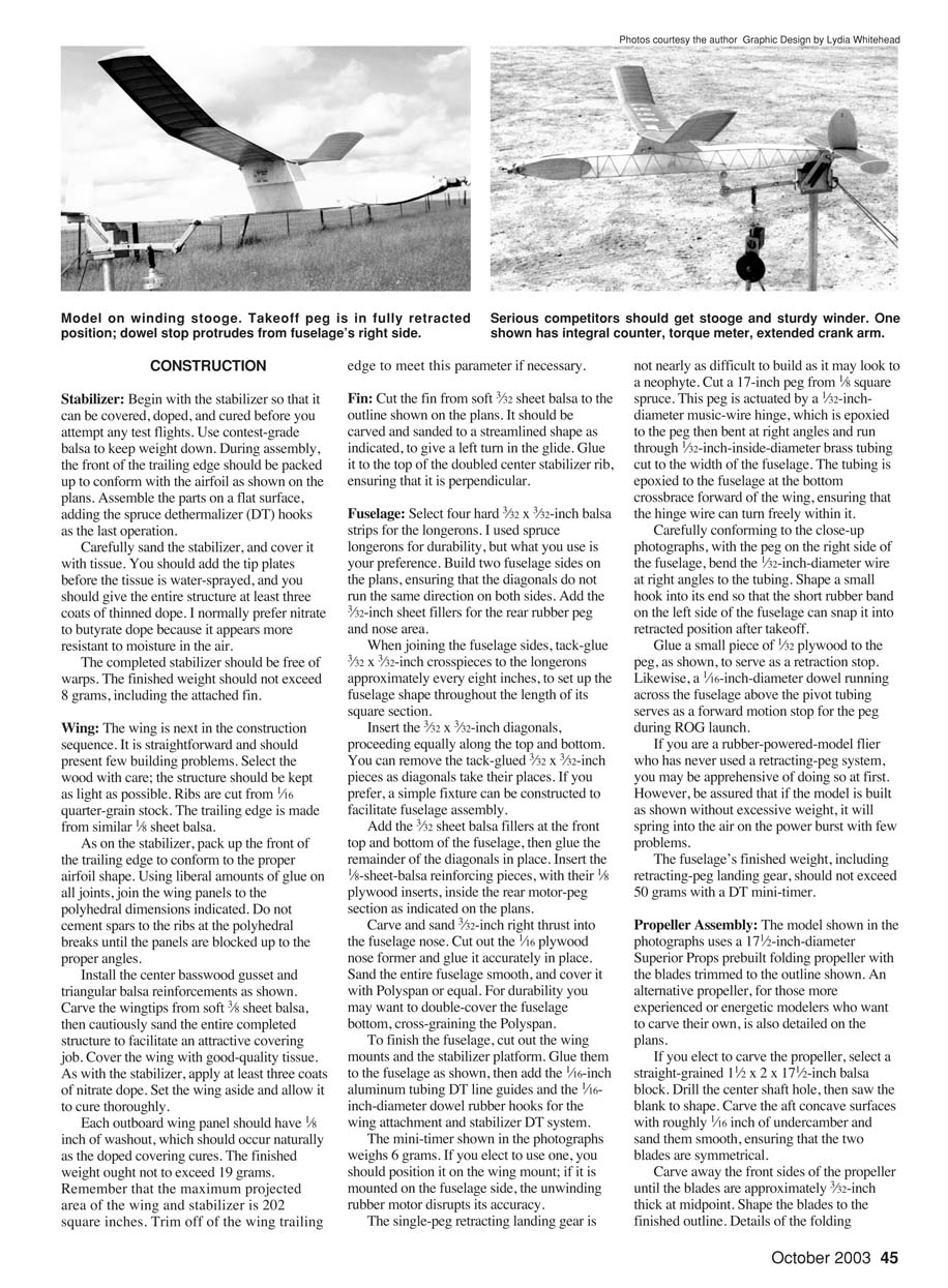
The single-leg retracting landing gear is not nearly as difficult to build as it may look to a neophyte. Cut a 17-inch peg from 1/8-inch square spruce. This peg is actuated by a 5/32-inch-diameter music-wire hinge, which is epoxied to the peg, then bent at right angles and run through 1/32-inch-inside-diameter brass tubing cut to the width of the fuselage. The tubing is epoxied to the fuselage at the bottom crossbrace forward of the wing, ensuring that the hinge wire can turn freely within it.
Carefully conforming to the close-up photographs, with the peg on the right side of the fuselage, bend the 1/32-inch-diameter wire at right angles to the tubing. Shape a small hook into its end so that the short rubber band on the left side of the fuselage can snap it into retracted position after takeoff.
Glue a small piece of 1/32-inch plywood to the peg to serve as a retraction stop. Likewise, a 1/16-inch-diameter dowel running across the fuselage above the pivot tubing serves as a forward motion stop for the peg during ROG launch.
If you are a rubber-powered model flier who has never used a retracting-peg system, you may be apprehensive at first. However, if the model is built as shown without excessive weight, it will spring into the air on the power burst with few problems.
The fuselage's finished weight, including the retracting-peg landing gear and a DT mini-timer, should not exceed 50 grams.
Propeller Assembly
The model shown uses a 17-1/2-inch-diameter Superior Props prebuilt folding propeller with the blades trimmed to the outline shown. An alternative for those willing to carve their own: select a straight-grained 1/2 x 2 x 12-1/2-inch balsa block. Drill the center shaft hole, then saw the blank to shape. Carve the aft concave surfaces with roughly 1/16 inch of curvature and sand them smooth, ensuring that the two blades are symmetrical.
Carve away the front sides of the propeller until the blades are approximately 3/32 inch thick at the midpoint. Shape the blades to the finished outline. Details of the folding hub are on the plans.
Complete the propeller assembly by carving the nose block from hard balsa, with its grain parallel to the fuselage axis. You can obtain the ball bearing, shaft, thrust bearing, and spring from FAI Model Supply. A 1/8-inch plywood insert glued to the rear of the nose block should fit into the front nose former. The propeller and nose block should be given at least three coats of dope before final assembly.
Ensure that the propeller blades are balanced and track properly. The finished weight of the propeller assembly, including the nose block, should not exceed 25 grams. A total airframe weight of 102 grams (3.60 ounces) thus exceeds the required minimum amount by a small margin.
Tailpost
The tailpost is 1/8-inch wire, bent slightly forward, inserted in a balsa block, and glued inside the fuselage top. The tail skid is a short length of music wire, epoxied into the fuselage bottom.
FLIGHT PREPARATION
Make at least two 3/16-inch rubber motors of 16 strands, 32 inches long. After washing, drying, and lubing the motors, break them in initially using the stationary stretch method: hammer two large nails—approximately six motor lengths apart—securely into a fence. Stretch the motor over the nails and leave it there for five to 10 minutes. The stretched motors should be roughly 33 inches long.
Assemble the completed model and insert a rubber motor. Check that the alignment and thrust offset are correct. Verify the balance point with the propeller blades folded. Shift the position of the DT timer if necessary to ensure that the balance point is located precisely as shown on the plans.
For the modeler interested in serious Moffett competition, a reliable, sturdy winder and a winding stooge are musts. The advantages of an immovable holder when winding and the freedom to test-fly alone are significant.
Under calm conditions, hand-glide the model and pack under the stabilizer leading or trailing edge until the model floats with a slight left turn.
This model should be docile to adjust under power. Start with approximately 200 turns. It should climb to the right, straighten out just before the propeller folds, then glide to the left. Use thrust adjustments and a rudder tab to obtain this pattern. Proceed in increments until maximum turns are reached. Under full power, the model should climb in a steep right corkscrew, with the nose pointed up until just before the propeller folds. Motor run should be roughly 50 seconds.
One advantage of the Moffett Rubber class is that the duration potential of the model exceeds the flight maximum unless down air is encountered. Therefore, unlike a contemporary Wakefield, it is not essential to wind the motor to capacity on every flight. Nor is a blast tube necessary unless you choose to use one for safety purposes.
I normally wind the motor on my Moffett to 800–850 turns, depending on the feel of the rubber. Maximum capacity is approximately 900 turns. Because of its smooth texture, FAI Model Supply rubber is normally resilient and unlikely to break unless mistreated. On several occasions I have used the same motor for all three competitive flights.
If you are unwilling or unable to build your Moffett Redux down to the structural weight shown on the plans and the climb suffers accordingly, I suggest an increase in power to 18 strands. One of the real joys of the Moffett Rubber event is to watch your model climb to an impressive height, which it may not do unless thermal-assisted if underpowered.
Good luck with your Moffett Redux.
William Langenberg 3189 Danville Blvd., Suite 285 Alamo, CA 94507
Sources:
- Balsa and spruce wood:
Sig Manufacturing Company, Inc. Box 520 Montezuma, IA 50170 (641) 623-5154
- Rubber, hardware, covering material:
FAI Model Supply Box 366 Sayre, PA 18840 (570) 882-9873
- Propellers:
Superior Props 516 Driftwood Cir. Slidell, LA 70458 (985) 726-9673
Transcribed from original scans by AI. Minor OCR errors may remain.

