

Nakajima - 2010/09
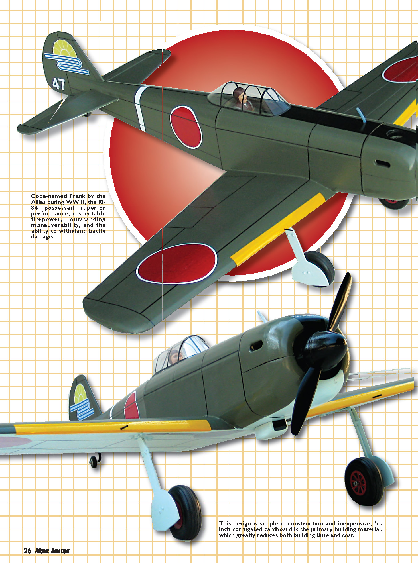
Code-named Frank by the Allies during WWII, the Ki-84 possessed superior performance, respectable firepower, outstanding maneuverability, and the ability to withstand battle damage.
This cardboard model of the Ki-84 Hayate is simple in construction and inexpensive. 1/8-inch corrugated cardboard is the primary building material, which greatly reduces both building time and cost. The design makes use of cardboard's unique features: the material can be used in large sections and folded. The wing is built from two large pieces, with cardboard ribs and a single spar. The tail surfaces and fuselage are primarily cardboard, with little internal bracing required. The result is a quick-to-build aircraft that has a scale-like appearance and can take plenty of punishment at the flying field.
I'll describe in the construction hints my method of folding the cardboard and using gummed paper tape to seal joints and exposed corrugations.
The Ki-84 has a wingspan of 60 inches and a length of 54 inches. The bottom of the airfoil is flat with a curved upper surface because of the scoring-and-folding technique I employed.
You can use a .40- to .50-size engine in this airplane. Mine is powered by a .40 and has a flying weight of 78 ounces. That figure combined with the 605-square-inch wing area results in a wing loading of 18.7 ounces per square foot.
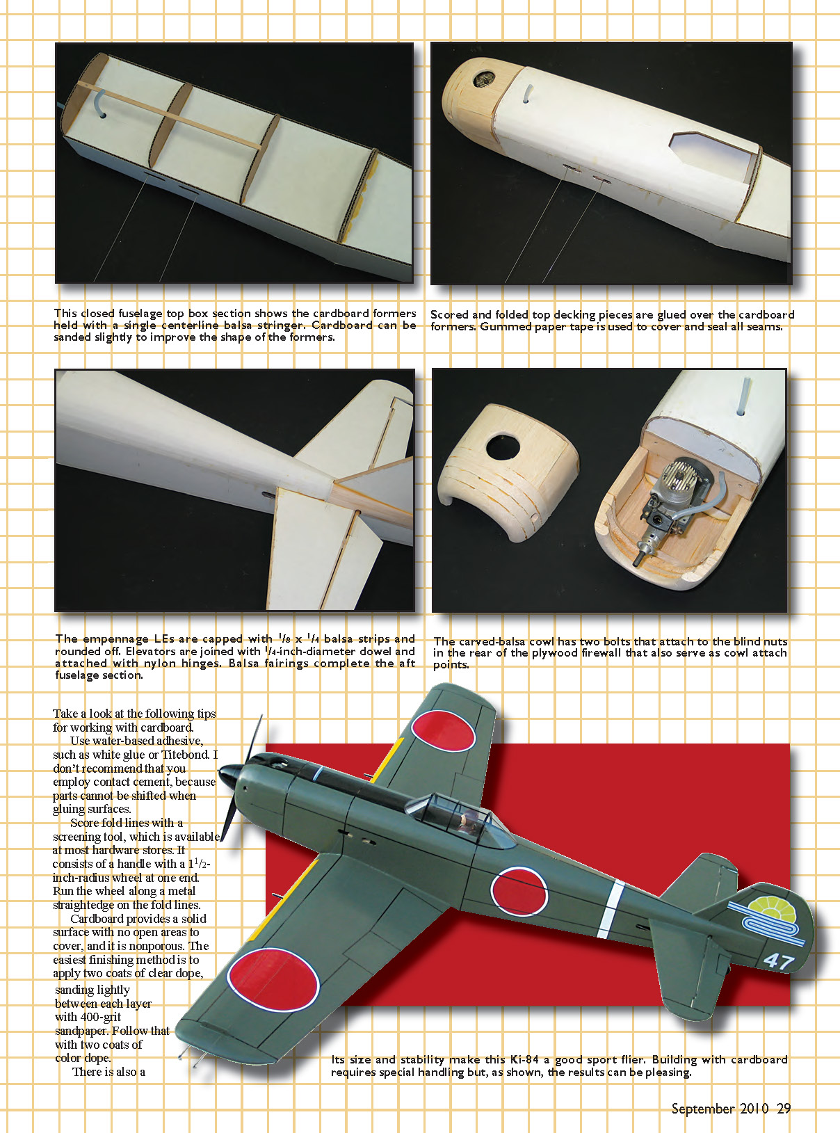
Its size and stability make this Ki-84 a good sport flier. Building with cardboard requires special handling but, as shown, the results can be pleasing.
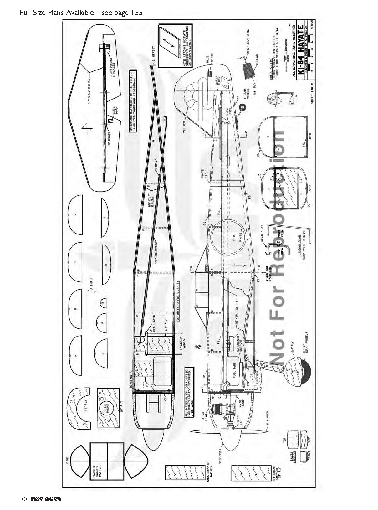
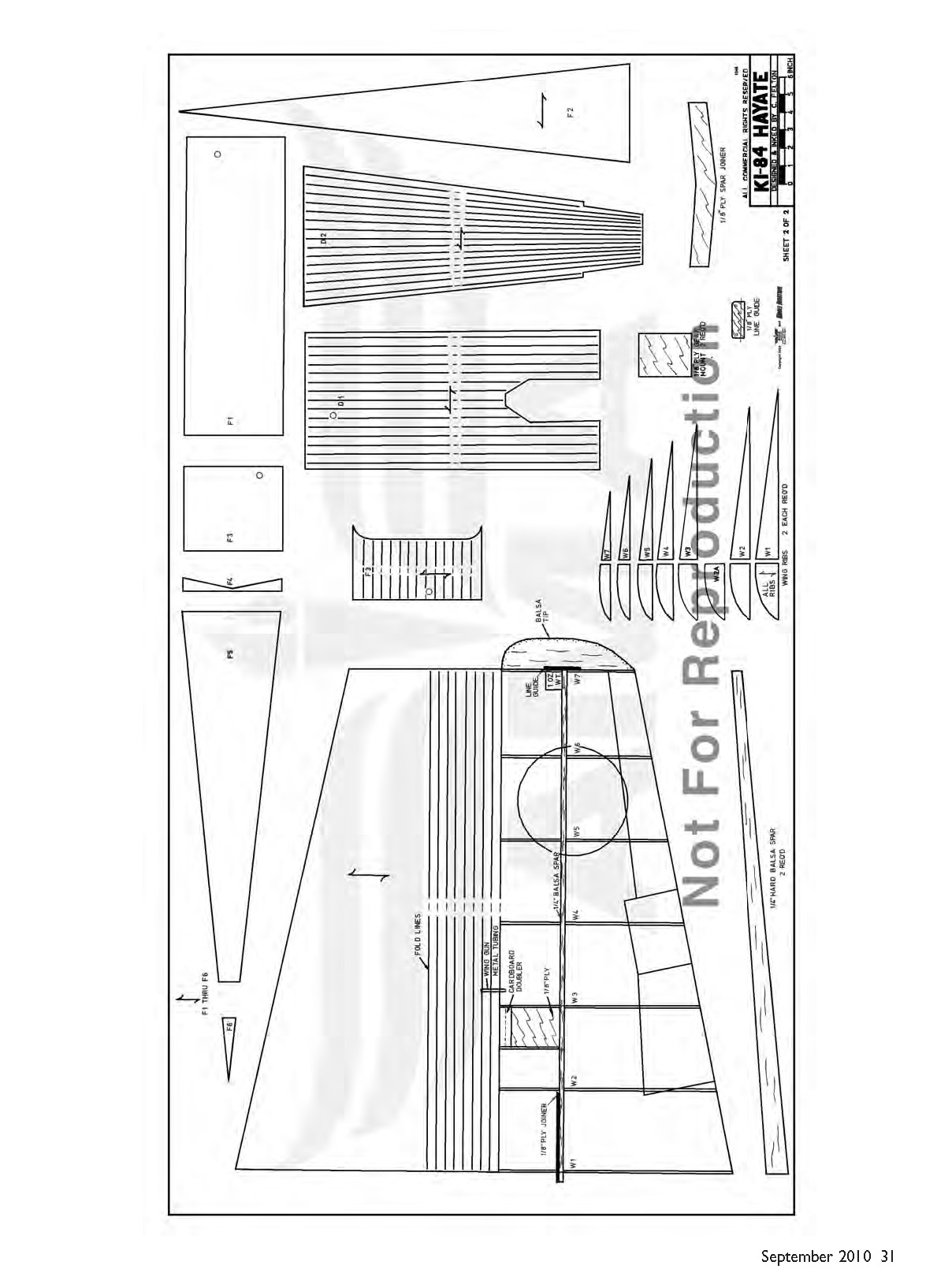
Full-size plans available — see page 155.
Tips for working with cardboard
- Use water-based adhesive, such as white glue or Titebond. Do not use contact cement, because parts cannot be shifted when gluing surfaces.
- Score fold lines with a screening tool (available at most hardware stores). It consists of a handle with a 1-1/2-inch-radius wheel at one end. Run the wheel along a metal straightedge on the fold lines.
- Cover all seams, joints, and exposed edges with strips of gummed paper tape. Obtain a 1-inch-wide roll from a stationery store. To use this material, cut a thin strip to length, dip it in water, and smooth it over the seam. Gummed paper tape adheres well to cardboard and sands smoothly.
- Cardboard provides a solid, nonporous surface. The easiest finishing method is to apply two coats of clear dope, sanding lightly between each layer with 400-grit sandpaper. Follow that with two coats of color dope.
- If you use heat-shrink coverings (Solarfilm, MonoKote) or vinyl paper, do not dope the surface of the cardboard first; this will cause the covering material to bubble.
- Make fuselage sides from a single sheet by scoring and folding. Glue the two halves together along the bottom; the resulting seam is strong and needs little reinforcement.
- Build wing panels directly on the plans. Use a straightedge when marking and cutting pieces. Use a plywood joiner for the spar slot to provide a durable connection between panels.
- The firewall is plywood and is mounted with blind nuts to accept the motor mount. The gear is sheet balsa with plywood supports. Balance the airplane by moving the tank and battery if necessary.
Specifications
- Type: CL Sport Scale
- Skill level: Intermediate
- Wingspan: 60 inches
- Wing area: 605 square inches
- Length: 54 inches
- Weight: 78 ounces (flying weight)
- Wing loading: 18.7 ounces/square foot
- Engine: .40–.50 two-stroke glow
- Construction: Plywood, balsa, corrugated cardboard
- Covering/finish: Fuelproof paint (as shown) or heat-shrink film
- Other: 6-ounce fuel tank, 3-inch spinner, 3-1/2-inch wheels, 1-inch tail wheel, engine mount, 3-inch bellcrank
Construction
Cut out all cardboard and wood parts, making sure to note the direction of the corrugations. Score and fold cardboard parts as the plans indicate.
Empennage
- The fin, rudder, stabilizer, and elevator are each made from two pieces of 1/8-inch-thick cardboard. Laminate them together cross-grain to make 1/4-inch-thick surfaces.
- Add a 1/8 x 1/4-inch balsa strip to the fin leading edge and round it off. Add 1/8 x 1/4-inch balsa strips to the stabilizer leading and trailing edges and round those off.
- Glue the elevators to a 1/4-inch-diameter dowel. Add 1/8 x 1/4-inch balsa strips to the remainder of the elevator leading edge and round off.
- Seal all raw edges with gummed paper tape. Hinge elevators to the stabilizer with nylon flex hinges at four places.
Wing
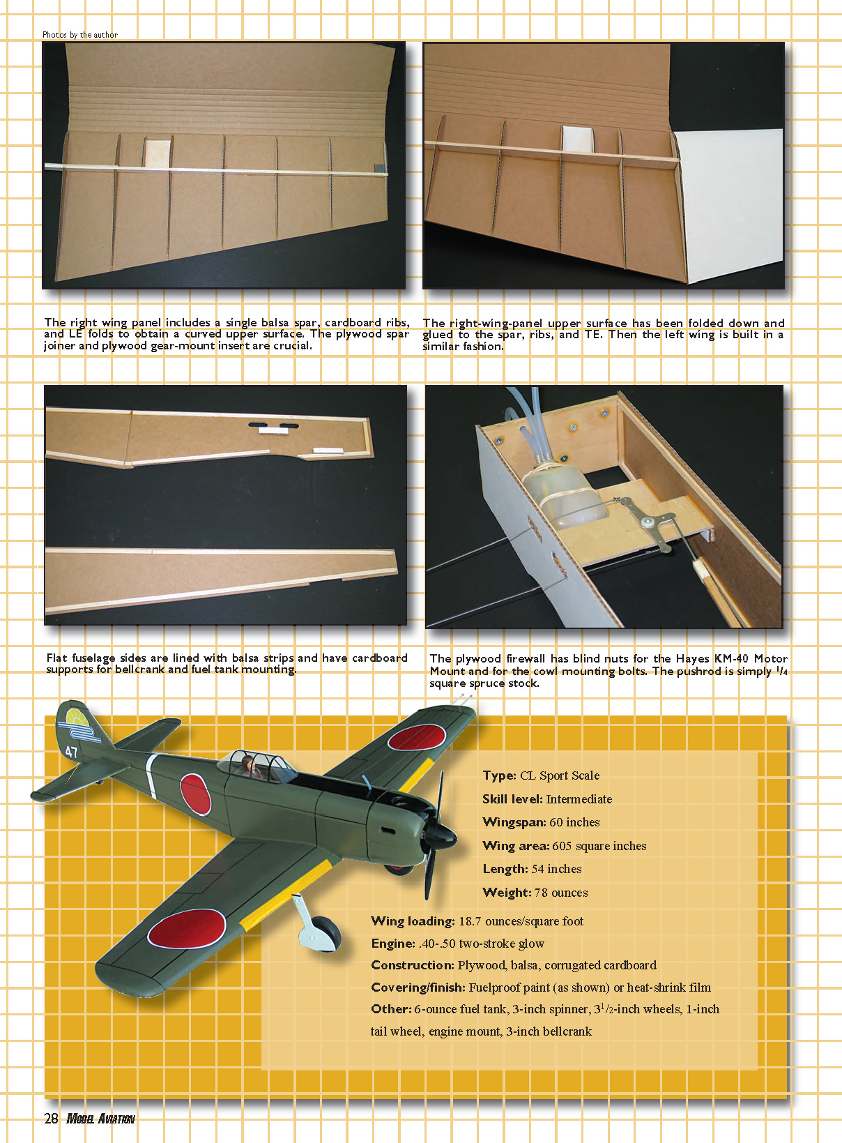
- Make the two wing spars from hard 1/4-inch balsa. Connect spar segments with a 1/8-inch plywood joiner on the forward side.
- Glue 1/8-inch plywood gear mounts into the bottom of each wing panel. Adhere the right-side spar into the bottom of the right-hand wing panel.
- Install ribs W1 through W7. Add a cardboard doubler over the plywood gear mount.
- Bond a 1-ounce weight to the right wingtip. Repeat left-side assembly: glue the left spar into the left panel, add ribs, and add the cardboard doubler over the plywood gear mount.
- Apply glue to the top of the wing spar, the top of the ribs, and the wing trailing edge. Fold each top wing surface down and pin securely in place until dry.
- Add balsa tips to the wing.
- Make a line guide from 1/8-inch plywood. Cut a slot in the left-wing balsa tip and glue the line guide in place.
- Cover the trailing edge, centerline seam, and wingtip seams with gummed paper tape.
- Use a plywood joiner for the spar slot to provide a durable connection between panels.
Fuselage
- Fuselage side edges are outlined on the drawing with a triangular symbol. Line the upper and lower edges of each fuselage side with 1/8 x 1/4-inch balsa strips, recessed 1/8 inch from the edges.
- Bevel the strips at the aft end so the cardboard sides will come together. Add cardboard supports to each fuselage side above the fuel tank and below the bellcrank.
- Make firewall C1 from 1/4-inch plywood. Locate mounting holes for the Hayes KM-40 motor mount on the face of C1. Drill mounting holes and install blind mounting nuts on the backside of C1.
- Drill a hole in C1 for the fuel line. Drill two holes in C1 and install blind nuts for the cowl hold-down bolts; these holes must align with holes in C2.
- Glue C1 to the right side of the fuselage. When dry, adhere the left side of the fuselage to C1.
- Attach the fuel tank to the 1/8-inch plywood support with rubber bands.
- Make a pushrod from 3/32-inch-diameter wire and 1/4-inch square spruce; attach it to the bellcrank along with the leadout wires. Install tank and bellcrank assemblies by gluing the plywood supports to the cardboard supports inside the fuselage. Bring the pushrod end out through the cutout in the left aft fuselage.
- Bond fuselage sides at the tail. Glue F1 and F2 in place to cover the top fuselage. Cover the bottom fuselage with F3, F4, F5, and F6. Make sure to bring out fuel-tubing fill and overflow lines during all covering operations.
- Add fuselage formers A through D to the top fuselage, adding a 1/8 x 1/4-inch centerline stringer. Cover bulkheads A through D with decking piece D1. Glue the horizontal stabilizer assembly to the rear fuselage.
- Add formers D through G with a centerline balsa stringer and cover with decking piece D2. Formers H and J are glued to the forward bottom fuselage with a centerline stringer and covered with decking piece D3.
- Fabricate the cowl from 1/2-inch balsa sheet and carve to shape. The bottom half is glued to the model, while the top half is removable. The top half has a 1/8-inch plywood former, C2, glued to the back. The two holes in C2 must align with the blind nuts in firewall C1.
- Sand, carve, and hollow the cowl to shape. Test-fit the engine in the cowl and drill mounting holes. Use a shaft extension to give adequate spinner clearance. Cut holes in the cowl block for the cylinder head, exhaust, and needle valve. Apply epoxy to the inside of the cowl and front of the firewall.
- Glue the rudder to the fin with the trailing edge offset 1/8 inch to the outside of the flying circle. Adhere the fin assembly to the fuselage/stabilizer. When dry, add balsa to the root of the fin and sand to fair into the fuselage shape.
- Make the tailwheel gear from 3/32-inch-diameter wire. Bend as shown on the plans, place on the 1/8-inch plywood support, wrap with nylon thread, and smear the thread with glue. When dry, glue in place in the bottom fuselage cutout.
- Bond the wing to the fuselage.
- Make the main gear from 7/32-inch-diameter wire. Make gear fairings from 1/8-inch plywood, and attach the gear assemblies to the 1/8-inch plywood supports in the bottom wing with nylon gear clips.
Final Assembly
- Give the model two coats of clear dope, sanding lightly after each coat with 400-grit sandpaper. Follow that with two coats of color dope.
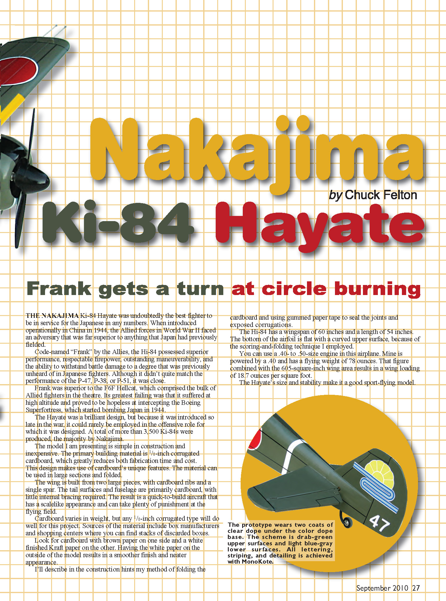
- The color scheme used consists of drab-green upper surfaces and light blue-gray lower surfaces. Lettering, striping, aileron outlines, and detailing were made from MonoKote.
- Make the canopy from thin plastic and use epoxy to attach it to the fuselage. Outline the canopy with thin strips of MonoKote.
- Pass leadout wires through the wingtip line guide and tie off. Attach the nylon control horn to the elevator and hook up the pushrod.
- Attach 3-1/2-inch-diameter wheels to the main gear and a 1-inch-diameter wheel to the tail gear.
- Add an 11 x 6 propeller and a 3-inch spinner to the engine. Ensure the model is balanced at the point shown on the plans.
Contact / Sources
- Chuck Felton
825 Lake Park Dr. Lakehills, TX 78063 http://home.earthlink.net/~charlesfelton [email protected]
If you have comments, suggestions, or questions concerning the cardboard Ki-84 Hayate, please contact me. I'd love to see a photo of your completed cardboard model.
Transcribed from original scans by AI. Minor OCR errors may remain.

