
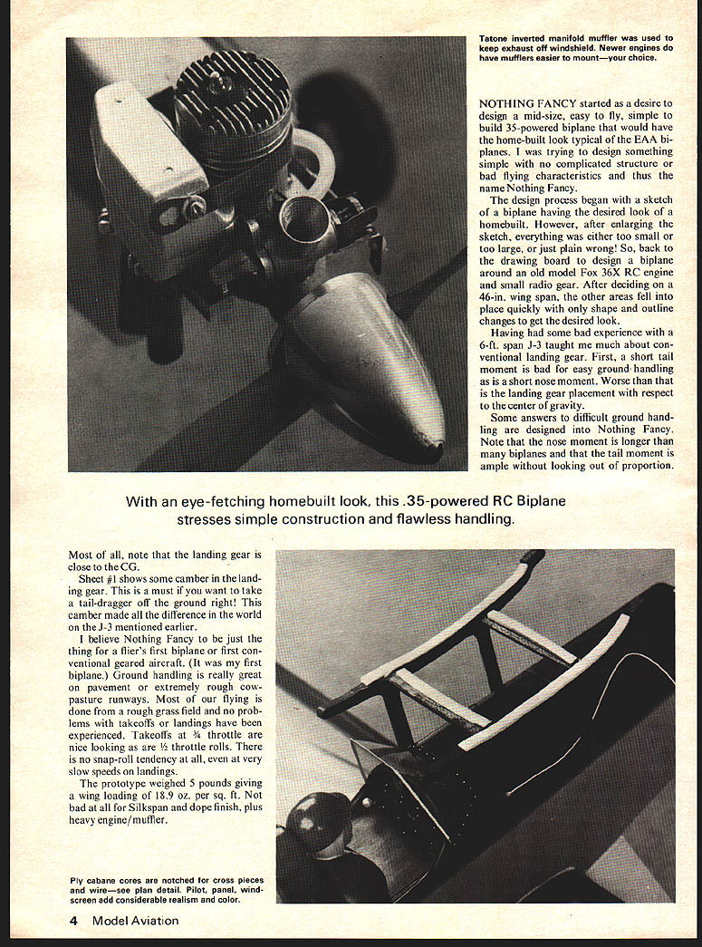
NOTHING FANCY
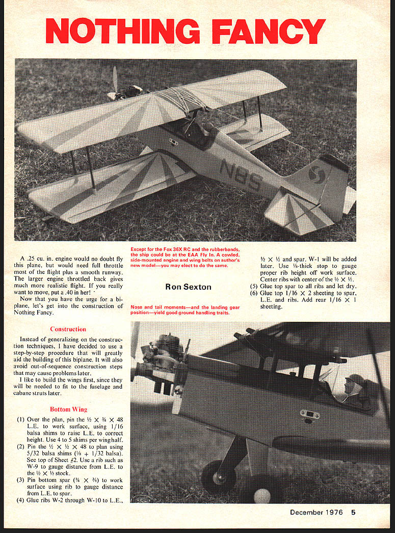
NOTHING FANCY started as a desire to design a mid-size, easy to fly, simple to build .35-powered biplane that would have the home-built look typical of the EAA biplanes. I was trying to design something simple with no complicated structure or bad flying characteristics and thus the name Nothing Fancy.
The design process began with a sketch of a biplane having the desired look of a homebuilt. However, after enlarging the sketch, everything was either too small or too large, or just plain wrong! So, back to the drawing board to design a biplane around an old model Fox 36X RC engine and small radio gear. After deciding on a 46-in. wing span, the other areas fell into place quickly with only shape and outline changes to get the desired look.
Having had some bad experience with a 6-ft. span J-3 taught me much about conventional landing gear. First, a short tail moment is bad for easy ground handling as is a short nose moment. Worse than that is the landing gear placement with respect to the center of gravity.
Some answers to difficult ground handling are designed into Nothing Fancy. Note that the nose moment is longer than many biplanes and that the tail moment is ample without looking out of proportion.
Most of all, note that the landing gear is close to the CG.
Sheet #1 shows some camber in the landing gear. This is a must if you want to take a tail-dragger off the ground right! This camber made all the difference in the world on the J-3 mentioned earlier.
I believe Nothing Fancy to be just the thing for a flier's first biplane or first conventional geared aircraft. (It was my first biplane.) Ground handling is really great on pavement or extremely rough cowpasture runways. Most of our flying is done from a rough grass field and no problems with takeoffs or landings have been experienced. Takeoffs at 3/4 throttle are nice looking as are 1/2 throttle rolls. There is no snap-roll tendency at all, even at very slow speeds on landings.
The prototype weighed 5 pounds giving a wing loading of 18.9 oz. per sq. ft. Not bad at all for Silkspan and dope finish, plus heavy engine/muffler. A .25 cu. in. engine would no doubt fly this plane, but would need full throttle most of the flight plus a smooth runway. The larger engine throttled back gives much more realistic flight. If you really want to move, put a 40 in her!
Now that you have the urge for a biplane, let's get into the construction of Nothing Fancy.
Construction
Instead of generalizing on the construction techniques, I have decided to use a step-by-step procedure that will greatly aid the building of this biplane. It will also avoid out-of-sequence construction steps that may cause problems later.
I like to build the wings first, since they will be needed to fit to the fuselage and cabane struts later.
Bottom Wing
(1) Over the plan, pin the 1/2 x 3/4 x 48 L.E. to work surface, using 1/16 balsa shims to raise L.E. to correct height. Use 4 to 5 shims per wing half.
(2) Pin the 1/2 x 1/2 x 48 to plan using 5/32 balsa shims (1/8 + 1/32 balsa). See top of Sheet #2. Use a rib such as W-9 to gauge distance from L.E. to the 1/2 x 1/2 stock.
(3) Pin bottom spar (1/4 x 3/8) to work surface using rib to gauge distance from L.E. to spar.
(4) Glue ribs W-2 through W-10 to L.E., 1/2 x 1/2 and spar. W-1 will be added later. Use 3/16-thick stop to gauge proper rib height off work surface. Center ribs with center of the 1/2 x 1/2.
(5) Glue top spar to all ribs and let dry.
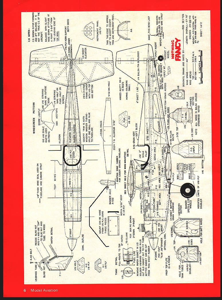
(6) Glue top 1/16 x 2 sheeting to spar, L.E. and ribs. Add rear 1/16 x 1 sheeting. CG NOTES CG shown is for forward and aft balance. It is not the true C.G. of the aircraft.
WINDSCREEN PATTERN
- 1/16 scale — score lightly.
- Use 0.020 acetate.
- Use 1/16 striping rivets (used tape on outside on prototype edge).
HATCH DETAIL F-I
- Recess blind nut into F-1 and use ZAP to glue nut and blind nut to wood.
- 4-40 bolt.
TANK DETAIL
- Tank fill/vent detail shown.
- Maintain some camber — full route to top for easier ground handling of hatch. Notch 3/32" deep.
MISCELLANEOUS NOTES
- Use 1/8" ply where shown.
- Use 1/16" ply elevator pushrod glue with 1/16" top to fuselage and bottom.
- Use small brass tube as shown for pushrod guides.
- Prop and spinner layout and tank mounting shown on plan.
(The remainder of this page consists of full-size plan views, part patterns, and assembly detail drawings for the Nothing Fancy biplane.) (7) After all has dried, saw wing along centerline to obtain two halves.
(8) Using dihedral gauge, mark angle on L.E. and 1/2 x 1/2 and saw or sand to this line on both panels.
(9) Glue dihedral braces into one panel.
(10) Glue W-1 ribs into each panel using dihedral gauge to set angle.
(11) Panels can now be glued together and 1/16 sheeting added to wing bottom.
(12) Glue bellcrank platforms in W-3 and W-4. Wire from servo to crank should be installed through holes and cranks mounted at this time.
(13) Glue center sheeting and cap strips.
(14) Add shaped T.E. to center section. Holes for bolts will be drilled later. Rub with glue into this area to help strengthen it.
(15) Fit and hinge ailerons to wing.
(16) Add tips; carve and sand to final shape.
(17) Cut 1/8 x 1/4 slots for outer wing struts in top of bottom wing.
(18) Place bottom wing aside for later matching to fuselage.
Top Wing
(1) Shim L.E. and 1/2 x 1/2 and pin to plan as in bottom wing. Pin bottom spar to plan.
(2) Install and glue all ribs.
(3) Add top spar, then 1/16 sheeting.
(4) After all has dried, remove wing from plan and glue on bottom 1/16 sheeting.
(5) Glue shaped T.E. to the 1/2 x 1/2 stock making sure alignment is straight.
(6) Add tips, cap strips and sand to shape.
(7) Cut 1/8 x 1/4 slots for outer struts in bottom of top wing.
(8) Set wing aside for later matching to cabane.
Stabilizer-Elevator
(1) Pin 1/8 x 1/4 strips to plan, cutting each to fit and gluing each in place.
(2) After glue has dried, remove from plan and glue structure to 1/16 x 4 balsa sheet. Lay 1/16 sheet on table and pin framework to it. Finish out with 1/16 covering with small piece at L.E.
(3) Add 1/16 sheeting to other side. Trim off excess and sand to shape.
(4) Into each elevator half, fit the 1/4 dowel before sanding the halves to airfoil shape.
(5) Glue dowel to both halves with both pinned flat on work surface.
(6) Carve and sand to shape. A line drawn on the T.E. of each half in the center of the thickness will aid in maintaining same shape for both halves.
(7) Add 1/16 ply inserts on side you intend pushrod to exit.
(8) Install hinges.
Fin-Rudder
(1) Cut fin and rudder to match plan outline.
(2) Sand fin to airfoil shape.
(3) Install 1/4 ply insert in rudder; drill hole for tailwheel wire and sand to shape.
(4) When installing hinges, remove hinge pins after alignment is complete. Rudder will have to be put on when tailwheel is fastened to fuselage. Replace hinge pins with #14 straight pins after rudder is installed.
Cabane Construction
(1) Cut two 3/32 ply cores to the outline shown on Sheet #2. In each one, cut a 3/32-in.-wide slot to accept the 3/32 music wire. Also notch for cross braces.
(2) Cut four 1/16 ply covers to the same outline as the cores.
(3) In two of these, cut a short slot 3/32 in. wide by about 1/4 in. long as indicated on the plan. Also notch for cross braces. These are the inside covers, others are the outside covers.
(4) Glue inside cover to core—make a left and a right.
(5) Spot glue outside covers to cores and sand to match.
(6) Bend up four 3/32 music wire struts to shape shown on plan. Try to keep these the same as much as possible.
(7) Do not glue wire in yet. Set both cabane struts aside for later finishing and fitting.
Fuselage
(1) Glue 1/4 squares to fuselage sides. Make a left and a right side. Use 1/16 scrap to gauge bottom 1/4-square locations.
(2) Fit and glue 1/16 ply doublers to fuselage sides. Lightly wet both side and doubler with water to stop warping.
(3) Glue 1/4 balsa wing saddle to fuselage sides.
(more)
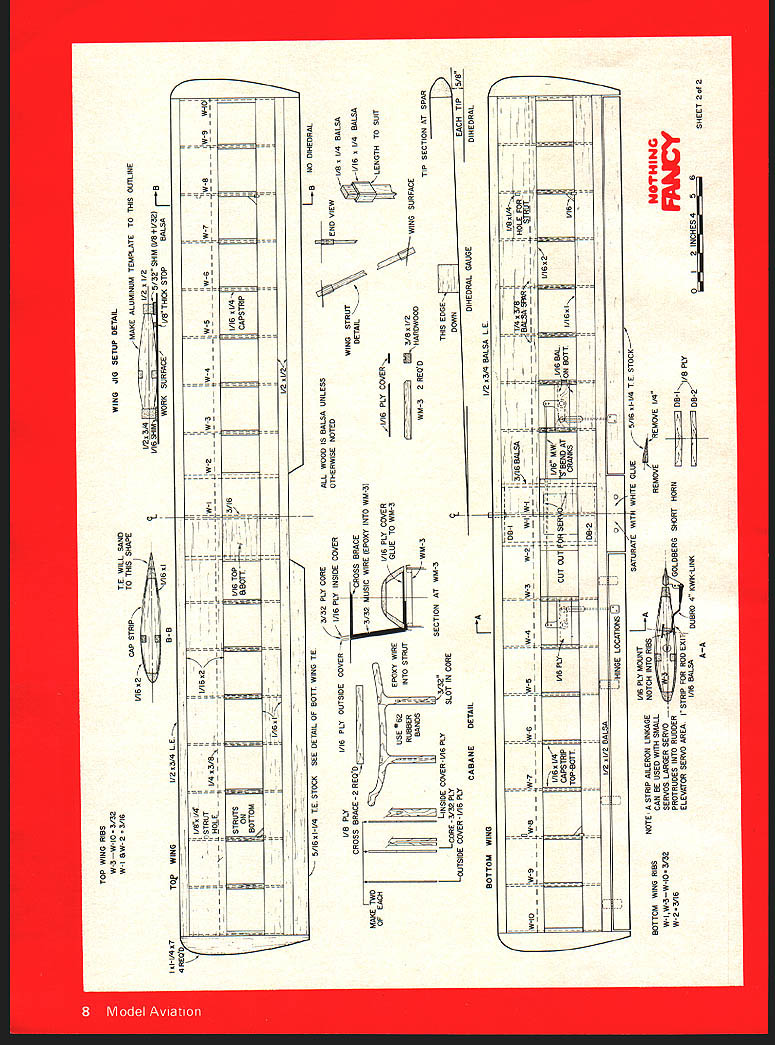
WING RIB SETUP DETAIL
TOP WING
BOTTOM WING
WING SURFACE
TIP SECTION AT SPAR
DIHEDRAL GAUGE
WING STRUT DETAIL
CABANE
MAKE TWO
USE 3/32 PLY CORE 1/16 PLY COVERS CROSS BRACE—1/16 PLY LOUISIDE COVER (looks to be "outside cover" on the plan)
WING SEAL USED ON FUSELAGE AND CABANE STRUT
CUT OUT 1/8 PLY 1/8 PLY
WING L WING R
CG NOTES
- CG SHOWN IS FOR FORWARD AND AFT BALANCE. IT IS NOT THE TRUE CG OF THE AIRCRAFT.
HATCH DETAIL F-1
- 4-40 BOLT
- 1/8 BRASS TUBE
- RECESS BLIND NUT INTO F-1 AND USE ZAP TO GLUE NUT AND BLIND NUT TO WOOD
ACOWl OUTLINE H-2 (ACOWL OUTLINE H-2) H-1 1/8 PLY
WINDSCREEN PATTERN
SCORE LIGHTLY
USE 1/16 SCALE USE 1/16 STRIPING
ELEVATOR PUSHROD
- GLUE WITH 1/16-TOP TO FUSELAGE AND BOTTOM 1/8 DIA HOLES
TANK DETAIL
- 2024 T-6 ALUMINUM
- MAINTAIN SOME CLEARANCE ROUTE TO TOP FOR EASIER GROUND HANDLING OF HATCH
- NOTCH 3/32 DEEP HINGES
SEE SHEET NO. 2 FOR WING MOUNTING
REMOVE PAPER GASKET IN LID — SOLDER
(Note: This sheet is the plan/detail sheet for "Nothing Fancy" — full-size wing, cabane and strut detail drawings and labels.) (4) Mark locations of F-2 and F-3 on inside of sides.
(5) Glue F-2 and F-3 to both sides and clamp together with fuselage resting over plan top view. Let fuselage sit on rear bottom section to help assure sides being parallel.
(6) Glue in F-4 and F-5 with fuselage resting on plan top view.
(7) After all has dried, glue in F-1 and clamp.
(8) Glue in F-2A, making sure location is correct.
(9) Add the two WM-3 hardwood rails with 1/16 ply glued to each. Use cabane struts to adjust distance between centers. Slots in WM-3 must line up with slots in cabane struts.
(10) Glue 1/4 balsa front sides to F-2A and F-2. Do not glue to F-1 or to the 1/4 squares from F-2 forward. Let 1/4 balsa front sides extend about 1 in. beyond F-1. This provides a place to tie or band the sides to F-1 until glue has set.
(11) Shape 1/4 balsa top sides to accept the 1/4 balsa top as shown in F-1 section.
(12) Glue H-1 in place. Glue only to hatch sides.
(13) Add 1/4 balsa top. Glue to F-2, F-2A, H-1 and to 1/4 top sides.
(14) After glue has dried, carefully saw through the 1/4 balsa at F-2 on the hatch line, thus cutting the hatch loose.
(15) Remove hatch from fuselage and add H-2 to the hatch and the 1/8 dowel to F-2.
(16) Hatch can be spot glued to F-1 and F-2 for shaping or can be shaped before step #14.
(17) Glue stab to fuselage sides making sure it is square to the centerline and to the fuselage sides.
(18) Add vertical fin making sure it is 90 degrees to stab and in center of fuselage and stab.
(19) Add 3/32 balsa top sheets, gluing edges to fin and stab. A short strip of 1/16 balsa can be placed between the 3/32 top and the 1/4 front sheeting (at the cockpit) to fill in between the two if necessary.
(20) Glue in WM-1, WM-2 and the 1/8 ply tailwheel mount.
(21) The 1/16 balsa bottom can now be added. Don't glue in the 1/16 bottom at front yet.
(22) Tape bottom wing to fuselage and mark dowel location through WM-1. Install dowel in wing. Holes for bolts can be drilled and tapped for nuts hold-down in WM-2.
(23) Add landing gear mount, 1/4-balsa bottom and 3/4 triangle stock at F-1.
(24) Shape balsa headrest to final form before gluing it to the fuselage.
(25) Fuselage can now be sanded to suit.
(26) Fuselage should be completely finished before installing cabane struts and before adding tail wheel and rudder.
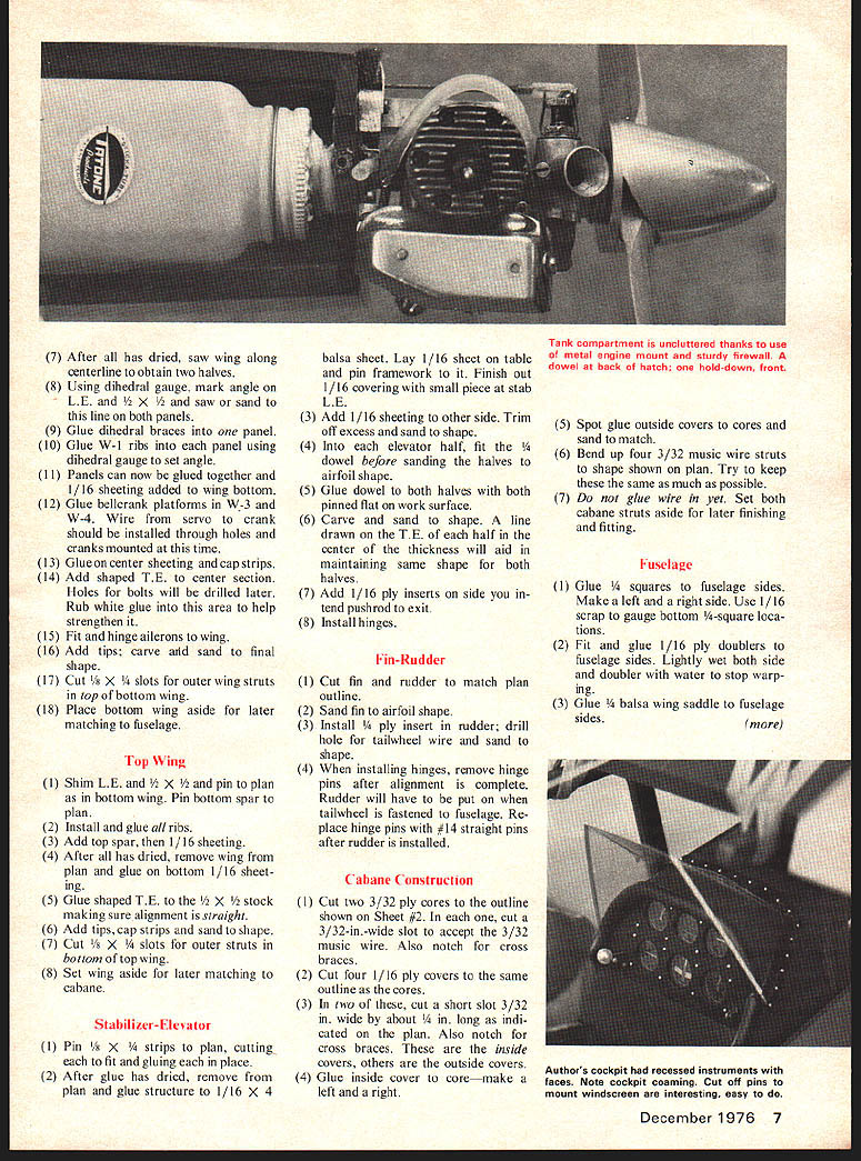
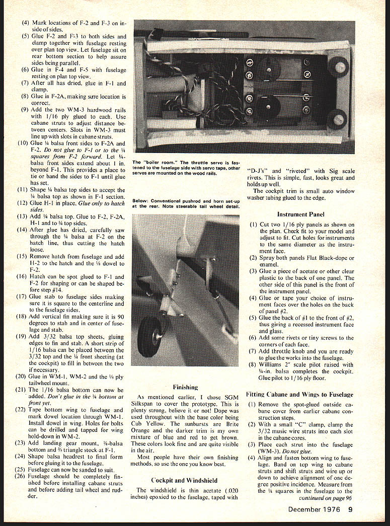
The "boiler room." The throttle servo is fastened to the fuselage side with servo tape, other servos are mounted on the wood rails.
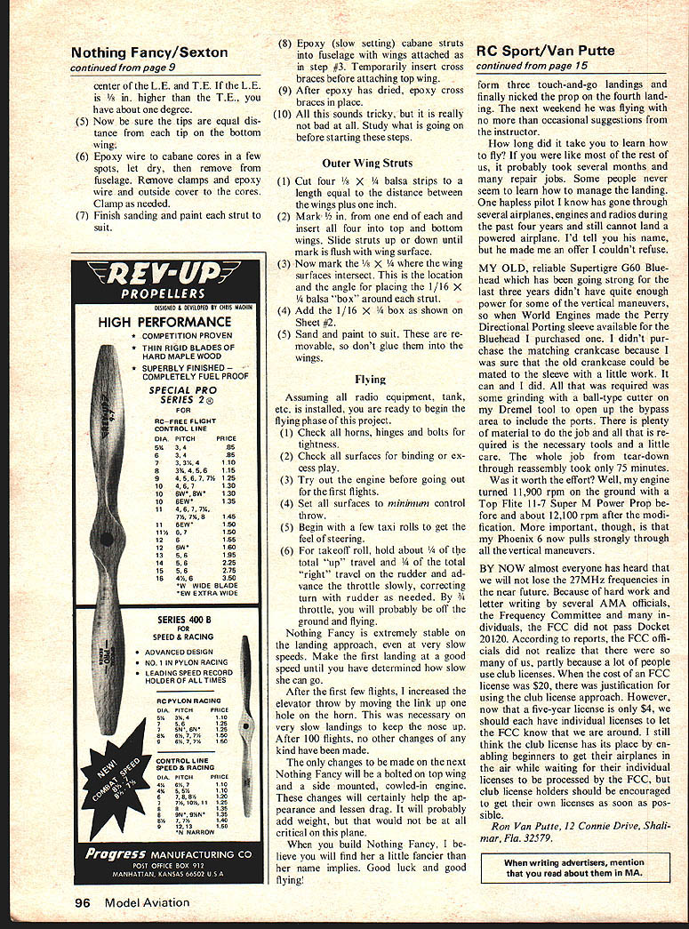
Below: Conventional pushrod and horn set-up at the rear. Note steerable tail wheel detail.
Finishing
As mentioned earlier, I chose SGM Silkspan to cover the prototype. This is plenty strong, believe it or not! Dope was used throughout with the base color being Cub Yellow. The sunbursts are Brite Orange and the darker trim is my own mixture of blue and red to get brown. These colors look fine and are quite visible in the air.
Most people have their own finishing methods, so use the one you know best.
Cockpit and Windshield
The windshield is thin acetate (.020 inches) epoxied to the fuselage, taped with "D-J's" and "riveted" with Sig scale rivets. This is simple, fast, looks great and holds up well.
The cockpit trim is small auto window washer tubing glued to the edge.
Instrument Panel
(1) Cut two 1/16 ply panels as shown on the plan. Check fit to your model and adjust to fit. Cut holes for instruments to the same diameter as the instrument face.
(2) Spray both panels Flat Black—dope or enamel.
(3) Glue a piece of acetate or other clear plastic to the back of one panel. The other side of this panel is the front of the instrument panel.
(4) Glue or tape your choice of instrument faces over the holes on the back of panel #2.
(5) Glue the back of #1 to the front of #2, thus giving a recessed instrument face and glass.
(6) Add some rivets or tiny screws to the corners of each face.
(7) Add throttle knob and you are ready to glue the works into the fuselage.
(8) Williams 2" scale pilot raised with 1/8-in. balsa completes the cockpit. Glue pilot to 1/16 ply floor.
Fitting Cabane and Wings to Fuselage
(1) Remove the spot-glued outside cabane cover from earlier cabane construction steps.
(2) With a small "C" clamp, clamp the 3/32 music wire struts into each slot in the cabane cores.
(3) Place each strut into the fuselage (WM-3). Don't glue.
(4) Align and fasten bottom wing to fuselage. Band on top wing to cabane struts and shift struts and wire up or down to achieve alignment of one degree positive incidence. Measure from the 1/4 squares in the fuselage to the center of the L.E. and T.E. If the L.E. is higher than the T.E., you have about one degree.
(5) Now be sure the tips are equal distance from each tip on the bottom wing.
(6) Epoxy wire to cabane cores in a few spots, let dry, then remove from fuselage. Remove clamps and epoxy wire and outside cover to the cores. Clamp as needed.
(7) Finish sanding and paint each strut to suit.
(8) Epoxy (slow setting) cabane struts into fuselage with wings attached as in step #3. Temporarily insert cross braces before attaching top wing.
(9) After epoxy has dried, epoxy cross braces in place.
(10) All this sounds tricky, but it is really not hard at all. Study what is going on before starting these steps.
Outer Wing Struts
(1) Cut four 1/8 x 1/4 balsa strips to a length equal to the distance between the wings plus one inch.
(2) Mark 1/2 in. from one end of each and insert all four into top and bottom wings. Slide struts up or down until mark is flush with wing surface.
(3) Now mark the 1/8 x 1/4 where the wing surfaces intersect. This is the location and the angle for placing the 1/16 x 1/4 balsa "box" around each strut.
(4) Add the 1/16 x 1/4 box as shown on Sheet #2.
(5) Sand and paint to suit. These are removable, so don't glue them into the wings.
Flying
Assuming all radio equipment, tank, etc. is installed, you are ready to begin the flying phase of this project.
(1) Check all horns, hinges and bolts for tightness.
(2) Check all surfaces for binding or excess play.
(3) Try out the engine before going out for the first flights.
(4) Set all surfaces to minimum control throw.
(5) Begin with a few taxi rolls to get the feel of steering.
(6) For takeoff roll, hold about 1/4 of the total "up" travel and 1/4 of the total "right" travel on the rudder and advance the throttle slowly, correcting turn with rudder as needed. By 3/4 throttle, you will probably be off the ground and flying.
Nothing Fancy is extremely stable on the landing approach, even at very slow speeds. Make the first landing at a good speed until you have determined how slow she can go.
After the first few flights, I increased the elevator throw by moving the link up one hole on the horn. This was necessary on very slow landings to keep the nose up. After 100 flights, no other changes of any kind have been made.
The only changes to be made on the next Nothing Fancy will be a bolted on top wing and a side mounted, cowled-in engine. These changes will certainly help the appearance and lessen drag. It will probably add weight, but that would not be at all critical on this plane.
When you build Nothing Fancy, I believe you will find her a little fancier than her name implies. Good luck and good flying!
Transcribed from original scans by AI. Minor OCR errors may remain.

