
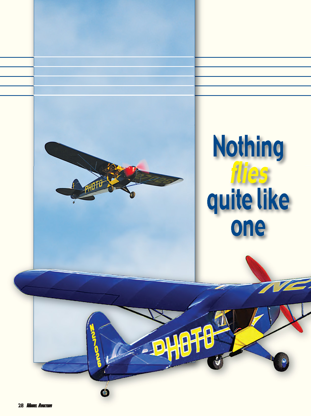

Nothing flies quite like one - 2010/08
If there is one aircraft that has come to represent all of the early lightplanes, it has to be the Piper Cub. Designed in 1937, the J-3 Cub was essentially an upgrade of the J-2, and it underwent a number of changes and improvements throughout the years.
Early J-3s were equipped with wood wing spars and the single-ignition Continental A-40 engine, which was later upgraded to the Continental A-50 and Lycoming O-145. Ultimately, many Cubs were equipped with Continental A-65s, 65-horsepower Lycomings, and a few 65-horsepower Franklins. Later models were upgraded to 75 horsepower, but the most common Cubs, including the L-4 Grasshoppers, were powered by the 65-horsepower Continental. The wood spars were replaced by extruded aluminum in later models.
There is irony in the Taylor/Piper story. While C.G. Taylor was hospitalized with appendicitis, William Piper put Walt Jamouneau to work on the J-2 upgrade. Upon C.G.'s return, Taylor and Piper had a falling out over the J-3 redesign and Taylor left the company to start his own venture, thinking that the new J-3 Cub would be a flop.
In all, 14,125 Cubs—civilian J-3s and military L-4s—were built during the design's 10-year production period, from 1937–1947. Today the Cub is as popular as ever, with nearly 4,000 J-3s and L-4s still flying.
During its long life span, the J-3 has been used to train countless military and civilian pilots. It has also provided many hours of enjoyment flying low and slow, watching the scenery slip by. It has been said that "the Cub is a great airplane as long as you don't have anywhere to go." Having spent many hours in the "family Cub" as a kid, the author says it's a great airplane whether you have a place to go or not.
The Model
If there is one aircraft that has been "overmodeled," it has to be the Piper Cub. It's a terrific and recognizable design that flies well. The author has built and flown several models of J-3s and Super Cubs in a variety of sizes and weights, and has loved them all.
A few years ago the author discovered that for park flying, 40-inch-span lightplanes were the perfect size and weight for GWS IPS power and flew beautifully as three-channel models, but they were also well suited for four channels. A collection of scale models is incomplete without the venerable J-3.
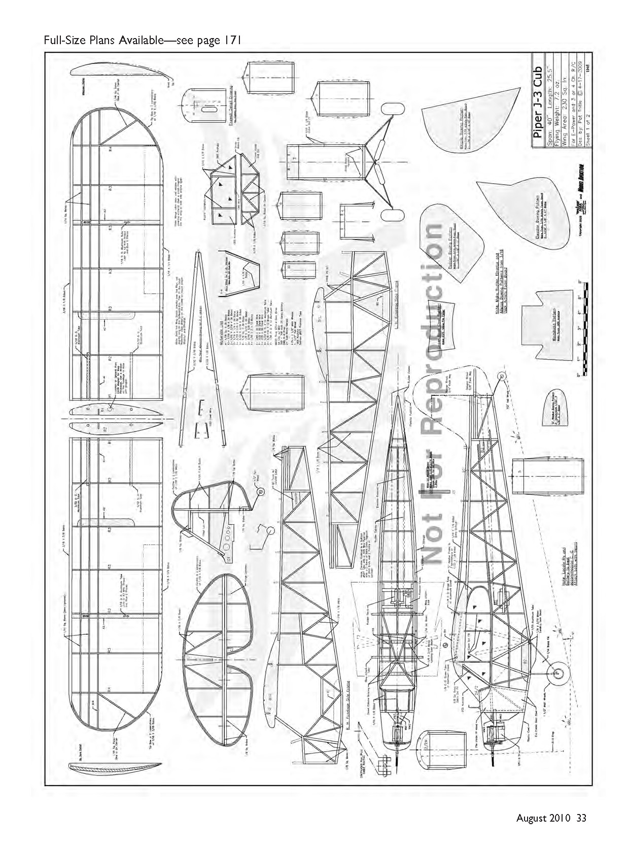
The 40-inch Cub described here was designed to be configured as either a three- or four-channel model by building the wing of choice. Since the wings plug into the fuselage, the design can be constructed both ways by fabricating a second set of wings.
Construction is primarily of balsa. The stick-and-tissue building style provides a nice scale appearance and a strong yet lightweight airframe that flies with economical power for scale-like flying qualities. The design features a functional cabin door for easy battery access. To keep the airframe light and sturdy, the wingtip and tail-section outlines and cabin "D" windows are bowed from laminated balsa.
CONSTRUCTION
Begin by bowing the laminated outlines. Make the bowing patterns from 3/16-inch-thick artist’s foam board using the templates provided. Soak some medium-firm wood in water for an hour or so to soften it. With the balsa pulled around the form and glued, you can put the wood in the microwave for 12–14 seconds to accelerate drying. See the Sources section for a web how-to on bowing outlines.
Pat's models are so lightweight that there is room for scale detail—such as bungee covers and a fuel-tank indicator float—without compromising performance.
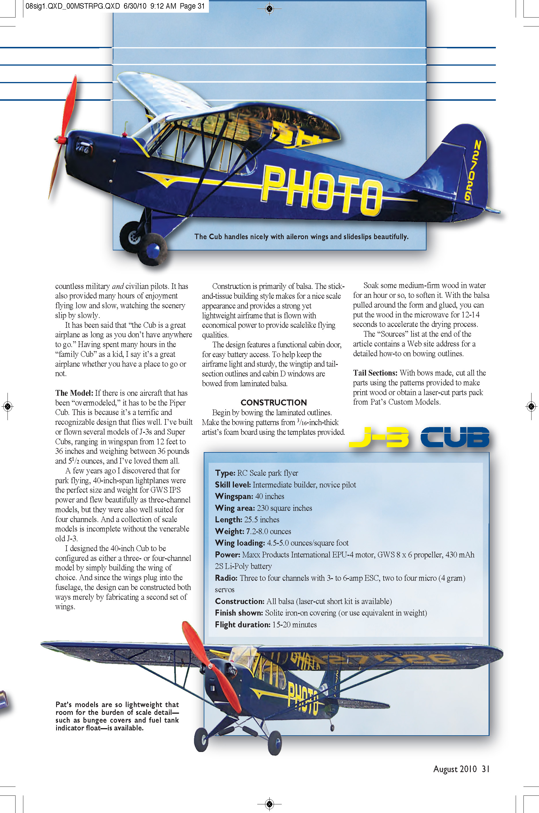
Specifications
- Type: RC scale park flyer
- Skill level: Intermediate builder, novice pilot
- Wingspan: 40 inches
- Wing area: 230 square inches
- Length: 25.5 inches
- Weight: 7.2–8.0 ounces
- Wing loading: 4.5–5.0 ounces/square foot
- Power: Maxx Products International EPU-4 motor, GWS 8 × 6 propeller, 430 mAh 2S Li-Poly battery
- Radio: Three to four channels with 3- to 6-amp ESC, two to four micro (4 gram) servos
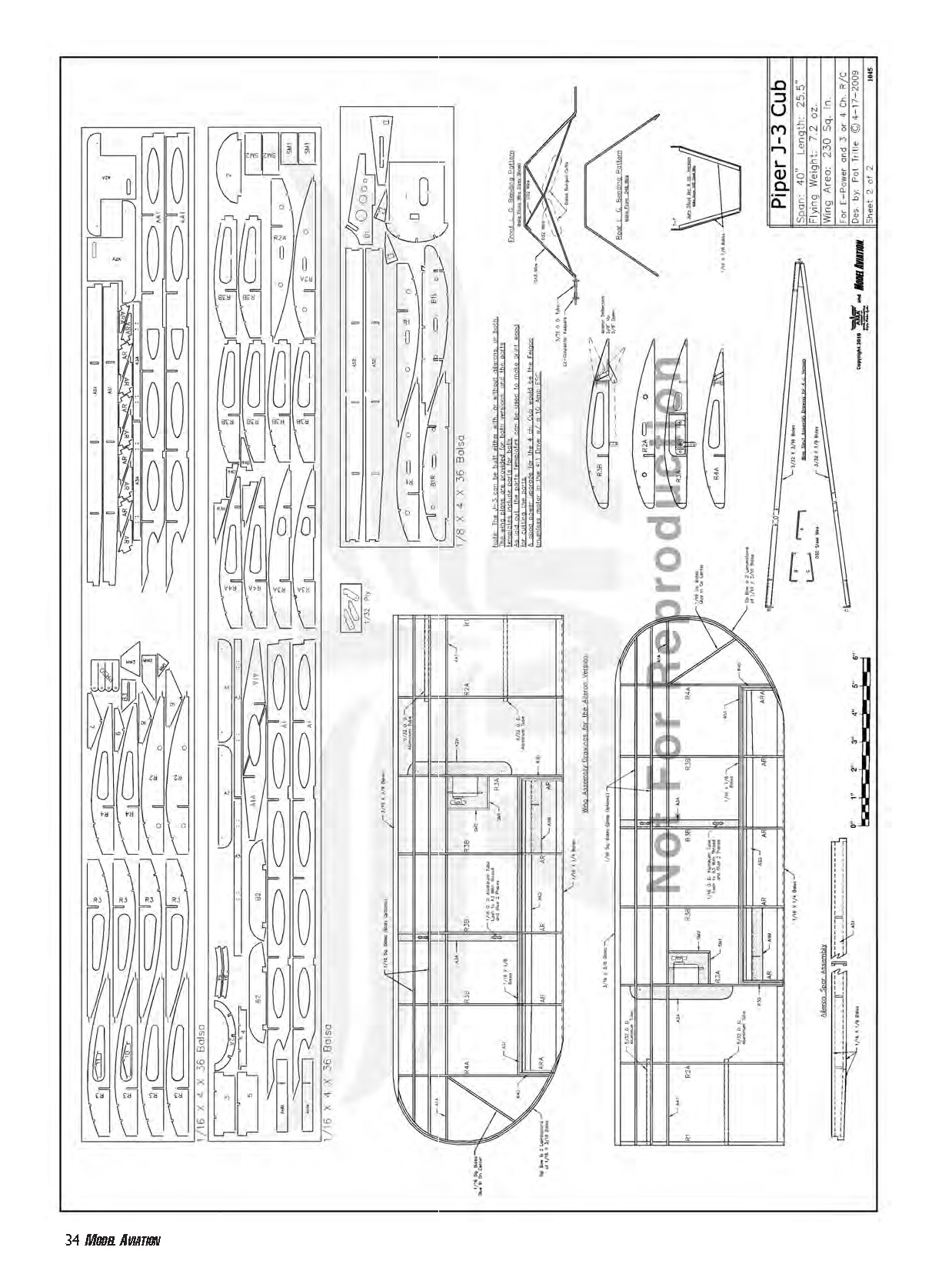
- Construction: All balsa (laser-cut short kit available)
- Finish shown: Solite iron-on covering (or equivalent in weight)
- Flight duration: 15–20 minutes
Tail Sections
- With bows made, cut all parts using the provided patterns or obtain a laser-cut parts pack from Pat's Custom Models.
- Build the rudder and horizontal stabilizer over the plans using the wood sizes shown. Pin shaped parts and frame the assemblies around them.
- When dry, remove from the board and sand to shape.
- Make hinges from 1/8-inch-wide strips of thin CA hinge stock, but do not glue them in until after the frames are covered.
- Bend the tail-wheel strut to shape from .032-inch wire using the provided pattern. Fit it into the rudder and glue in place.
Wing
Before beginning wing construction, decide whether you will build the three-channel (no ailerons) version, the aileron version, or both. Plans and parts are provided for both assemblies—keep a close eye on part numbers.
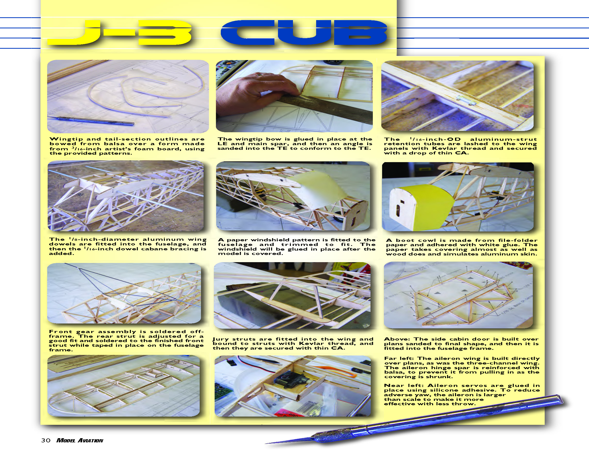
- The wingtip and tail-section outlines are bowed from balsa over a form made from 3/16-inch artist's foam board, using provided patterns.
- The wingtip bow is glued in place at the leading edge (LE) and main spar; an angle is sanded into the trailing edge (TE) to conform to the TE.
- The 1/16-inch-OD aluminum strut-retention tubes are lashed to the wing panels with Kevlar thread and secured with a drop of thin CA.
- The 1/8-inch-diameter aluminum wing dowels are fitted into the fuselage; the 1/16-inch dowel cabane bracing is then added.
- A paper windshield pattern is fitted to the fuselage and trimmed; the windshield will be glued in place after covering.
- A boot cowl is made from file-folder paper and adhered with white glue; the paper takes covering almost as well as wood and simulates aluminum skin.
- The front gear assembly is soldered off-frame. Adjust the rear strut for a good fit and solder to the finished front strut while taped in place on the fuselage.
- Jury struts are fitted into the wing and bound to struts with Kevlar thread, then secured with thin CA.
Three-channel wing (overview):
- Pin parts A2 and A3 over the wing plans. Dry-fit ribs R2, R3, R4 onto main spar A1.
- Pin the 1/16 × 1/4 TE over the plans, add the rib/spar assembly and glue.
- Fit and glue R1 ribs, 3/16 × 3/8 balsa LE, and tip bow.
- Cut 5/32-inch-OD aluminum socket tubes to length and glue into the wing at R1 and R2; adhere 1/16-square balsa top spars.
- When dry, remove panels from the board and sand to shape.
Aileron wing (overview):
- Pin A2A and A3A over plans. Build aileron spar assemblies (make left and right).
- Assemble ribs R2A, R3A, R3B, R4A onto main spar AA1; pin 1/16 × 1/4 TE.
- Attach rib/spar assembly and aileron spar AS1, glue in place.
- Fit R1 ribs, 3/16 × 3/8 balsa LE, and tip bow; install 5/32-inch socket tubes and 1/16-square top spars.
- Sand a bevel into aileron hinge spar AS2 using R3B detail as reference. Glue aileron ribs AR and ARA on AS2, then glue the assembly to the TE.
- Remove wing from board, sand, cut aileron free, sand to final shape, and fit AH1 flush with the bottom of the aileron assembly.
- Cut aileron hinges 5/32 inch wide and fit them in the aileron (do not glue until after covering).
- Fit and glue SM1 and SM2 servo mount gussets on A2A. Neutral the servo, screw on the output arm, and bond it to the mount with silicone adhesive.
Notes:
- Dihedral is set up by the two root ribs since the wing panels plug in—select components carefully.
- Twist approximately 1° of washout into the wing panels; ensure both sides match.
Fuselage
- Build side frames over the plans. Right and left frames differ because the side door opens on the right.
- Pin B1L and B1R and frame sides around them. Locate and glue B2 to the inside of each frame and adhere B3 flush with the outside edge of the right-hand frame.
- When dry, remove frames from the board. Make landing-gear beams from 1/8 × 3/16 balsa and gouge slots for beams; pin in place over the top-view drawing.
- Using triangles or machinist's squares to ensure vertical alignment, glue fuselage sides to the landing-gear beams (door on right).
- Assemble former 2/2A and glue in place along with cabin formers 3, 4, 5, and 6. Adhere B4 ribs between formers 3 and 4.
- Sand the bevel into fuselage sides at the tail end. Pull tail post together and glue. Fit formers 7–11 on top of fuselage.
- When dry, remove frame from board and add all 1/16 × 1/8 balsa bottom crosspieces.
- Glue former 1 in place flush with front of fuselage frame. Note motor-mount-stick hole orientation—offset for right thrust.
- Build up motor mount and glue it to the firewall. Add balsa stringers and cabin outfill, then sand to shape.
- Above: side cabin door is built over plans, sanded to final shape, and fitted into the fuselage frame.
Fitting Wing Struts
- Build wing lift struts over the plans; two patterns provided for different dihedral angles.
- Cut struts a bit overlength on the outboard end for final trimming.
- Bend .032-inch-diameter wire retention clips to shape and adhere the bottom clip on the struts.
- Cut six pieces of 1/16-inch-OD aluminum tube, 5/16 inch long. Lash strut retention tubes in place on fuselage and wings with thread and secure with thin CA.
- Cut 1/8-inch-OD aluminum dowel to 7/32 inch long for wing mounting pins and slip into the fuselage.
- Slide wing panels onto dowels, fit struts into fuselage tube sockets, trim front strut to length, set up outer fittings and glue into the struts.
- Trim rear struts, fit retention clips into the strut, and glue. Do not glue retention clips into the tubes (so struts can be removed).
- Bend jury struts to shape, slip into holes in A2/A2A, align vertically, lash to lift strut with thread, and secure with thin CA.
- Add 1/16 × 1/8 balsa strut fairings to the jury struts to complete them.
Landing Gear
- Using provided patterns, bend landing gear components from appropriate wire sizes.
- Lay out the front strut and solder together using Stay-Brite silver solder. Tape front and rear struts to fuselage and solder.
- Remove gear assembly and wash with soap and water to prevent corrosion.
- Bind the landing gear assembly to the beams with thread and secure with thin CA. Add 1/8-inch scrap balsa gussets and 1/16-inch balsa fill.
- Make boot cowl sections from yellow file-folder material and adhere with white glue: bottom, sides, then top.
- Complete fuselage assembly by building upper and lower cabin side doors over plans and sanding to shape.
Mounting Servos and Motor
- Glue servo mount rails and beams into the fuselage; space rails to fit your servos.
- Screw servos in place and run the elevator pushrod tube (Sullivan item 507), supported at both ends and mid-span using short sections of pushrod sheathing as standoffs. The pushrod is .025-inch-diameter wire.
- Fit rudder and elevator into the fuselage and run rudder pull-pull cables per the routing diagram. Tie cables off on the toothpick control horn and mark the exit location on the plans.
- Set up motor and ESC, test rotation, fit motor onto mount stick and secure with a dab of silicone adhesive.
- Assemble the model and double-check access and potential issues before covering.
Covering
You can cover the Cub with tissue and dope, light silkspan and dope, or iron-on covering. Recommended iron-on materials for this lightweight structure are Coverite Airspan or Litespan if you want a doped-tissue look. A good Mylar is Coverite Microlite (also sold as Nelson Hobby Specialties' LiteFilm and So-Lite).
Do not use heavier, highly shrinking iron-on materials such as MonoKote or UltraCote—their excessive shrinkage and weight can damage the light structure and degrade flying qualities.
- Cover all frames except the vertical fin and fuselage top.
- With frames covered, plug in the wings and fit the horizontal stabilizer into the fuselage; align using the wings and adhere in place.
- Align and glue the vertical fin. Cover the top of the fuselage and vertical fin using separate pieces of covering for left and right sides to form a fillet at the base of the fin.
- Hinge the side door to the fuselage using hinge tape or covering material. Add trim as desired—Callie Graphics has the author's trim scheme and can provide custom graphics.
Final Assembly
- Carve the cowl and dummy engine from blue foam or balsa, or use a vacuum-formed cowl from the parts pack. Fit the cowl and screw in place with small sheet-metal screws.
- Seal struts with a couple coats of water-based varnish or dope; paint with Model Master Acryl.
- Glue hinges in place in rudder and elevator with Pacer Formula 560 Canopy Glue or equivalent.
- Run in the elevator pushrod, Z-bend the back end, set elevator neutral, and glue the control horn in place.
- Mark rudder cable exit points on the fuselage, reinforce the covering with tape or vinyl trim stock, pierce at exit points, run the rudder cables into the fuselage, and tie to the control horn.
- Drill holes in the vertical fin and horizontal stabilizer and run tail-brace rigging using light Kevlar thread. Adhere aileron hinges in place.
- Make aileron pushrods from .032-inch-diameter wire with Z-bends on both ends. Fit onto servo and control horn, align aileron neutral, and glue horn in place.
- Use brass tubes to size wheel holes down to 3/32-inch ID. Fit 3/32-inch-OD tubing to the axles and epoxy in place.
- Mount wheels using Du-Bro E/Z Connector plastic keepers on both sides of each wheel.
- Fit and glue side windows and windshield using .005–.008 acetate. Add remaining details as desired.
- Set the CG as shown on the plans, using battery and receiver locations to your best advantage. Mount components on 1/16-inch hard balsa plates and secure with Velcro.
- Set up controls per the plans.
Flying
- The three-channel Cub is easy to fly but slightly sensitive to windy conditions—test-fly on a calm day.
- Before first flight, double-check control throws and directions to avoid reversed controls.
- The model should trim for straight-and-level flight at approximately two-thirds power. Controls are positive but not overly sensitive.
- For the four-channel version, rudder is used on takeoff (left hand). Ailerons induce some adverse yaw; use rudder to coordinate turns.
- Rudder-to-aileron mixing can help coordination but will make sideslipping more difficult. Differential aileron throw can reduce adverse yaw.
- The little J-3 handles well, slows nicely for touch-and-goes, and will do pleasing scale loops when entering a shallow dive and pulling over the top in a "Cub-style" teardrop shape.
- Enjoy—this design flies with classic, scale-like Cub characteristics.
Pat Tritle [email protected]
Sources
- Making Bowed Outlines
http://patscustom-models.com/Bowed%20Outlines.htm
- Pat's Custom Models
(505) 296-4511 www.patscustom-models.com
- GWS USA
(909) 594-4979 www.gwsus.com/english/dealer/dealer_gwsusa.htm
- Sullivan Products
(410) 732-3500 www.sullivanproducts.com
- Nelson Hobby Specialties
(817) 431-1038 www.nelsonhobby.com
- Du-Bro
(800) 848-9411 www.dubro.com
- EPU-4 motor: Maxx Products International
(847) 438-2233 www.maxxprod.com
- Callie Graphics
(505) 281-9310 www.callie-graphics.com
Transcribed from original scans by AI. Minor OCR errors may remain.

