
Virtual adverse yaw explained
Let's conclude the cause-and-cure discussion about virtual adverse yaw that began in my June column. I described the climbout of a rudder-elevator (no ailerons) Old-Timer RC aircraft that was behaving oddly. The airplane was climbing out in a right turn as planned, but with the left wing low.
These aircraft use rudder to start a turn. That produces yaw, causing the dihedral in the opposite wing to present a greater angle of attack. That wing then lifts, helping turn in the low-wing direction. The low wing also helps the turn by acting in the opposite direction. When the dihedral angle is anywhere near optimum, the turn looks the same as a well-coordinated aileron turn. A low left wing should be associated with a left, not a right, turn.
The airplane was out of trim, but I didn't understand why it was turning right instead of left. A sharp observer would have immediately solved that problem, but I was a little slow. It had to do with the pilot's mental state, which some might impolitely call "semiconscious." I was applying right rudder without being cognizant of the stick movement. The connection was traveling from eyes to fingers, bypassing the brain. I've since considered rewiring to include the brain, especially when making trim flights.
The aircraft was out of trim because there was uneven washout or warpage between the two wings, requiring correction. Micafilm stubbornly resists adjusting warps, so I used my pet method for battling these tough cases. An old hot-air popcorn popper was positioned under a wing, while a heat gun worked the top side as the twisting took place. Both sides of the wing now had equal washout, but the next trim flight showed that the condition wasn't completely cured.
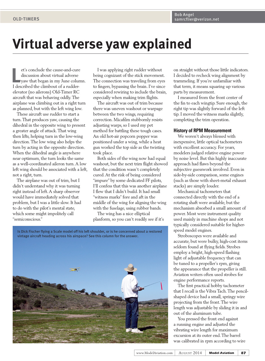
At the risk of being considered "impure" by some dedicated FF pilots, I'll confess that this was another airplane I flew that I didn't build. It had small "witness marks" fore and aft in the middle of the wing for aligning the wing with the fuselage, using rubber bands. The wing has a nice elliptical planform, so you can't readily see if it's on straight without those little indicators. I decided to recheck wing alignment by trammeling. If you're unfamiliar with that term, it means squaring up various parts by measurement.
I measured from the front center of the fin to each wingtip. Sure enough, the right tip was slightly forward of the left tip. I moved the witness marks slightly, completing the trim operation.
History of RPM Measurement
Early methods and limitations
We weren't always blessed with inexpensive, little optical tachometers with excellent accuracy. For years, modelers judged relative engine power by noise level. But this highly inaccurate approach had flaws beyond the subjective guesswork involved. Even in side-by-side comparison, some engines (such as those with sheet-metal exhaust stacks) are just louder.
Mechanical tachometers that connected directly with the end of a rotating shaft were available, but the mechanism absorbed a small amount of power. Most were instrument quality used mainly in machine shops and not typically considered suitable for higher-speed model engines.
Stroboscopes were available and accurate, but were bulky, high-cost items seldom found at flying fields. Strobes employ a bright, high-speed flashing light of adjustable frequency that can be tuned to a propeller's rpm, giving the appearance that the propeller is still. Aviation writers often used strobes for engine performance reports.
The Vibra Tach
The first practical hobby tachometer that I recall is the Vibra Tach. The pencil-shaped device had a small, springy wire projecting from the front. The wire length was adjustable by sliding it in and out of the aluminum tube.
You pressed the front end against a running engine and adjusted the vibrating wire length for maximum excursion at its outer end. The barrel was calibrated in rpm according to wire length. The marks were exponential, with closer marks for the higher rpm where the wire became shorter. They were affordable at roughly $2.
One variation of the Vibra Tach used a flat reed rather than the springy wire. Another consisted of a flat, comb-like device with a series of reeds of varying lengths. You simply selected and read the rpm printed on the reed that was vibrating the most.
Audio tachometers
Audio tachometers began to appear. In simplest form, musical pitch pipes were used to approximate rpm by blowing into various pipes until the pitch matched the engine sound.
Charts showed the specific frequency of each tone on the musical scale. Sometimes engine sound recordings were taken and later played back while comparing notes on a piano. Obviously, there were improvements to be made in audio tachometers.
Plans for more sophisticated electronic audio tachometers appeared in model magazines. These were portable devices producing an adjustable frequency sound and featuring one earplug/speaker. You simply dialed in a calibrated sound frequency corresponding with the engine rpm.
I can't keep up with today's technology, but there's probably a smartphone app that can be used to match sound frequency to engine sound.
Audio tachometers allow in-flight rpm readings, but they can also produce reading errors because of the Doppler effect, named after Austrian physicist Christian Doppler. An aircraft climbing away, for instance, would show slightly lower than actual rpm because the Doppler effect "stretches" the sound waves. CL speed airplane readings need to be taken from the center of the circle to prevent the Doppler effect from messing up the tachometer’s readings.
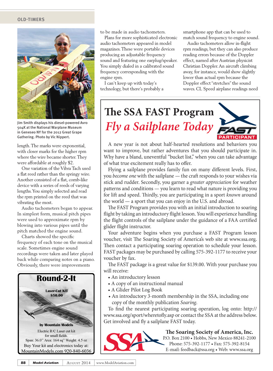
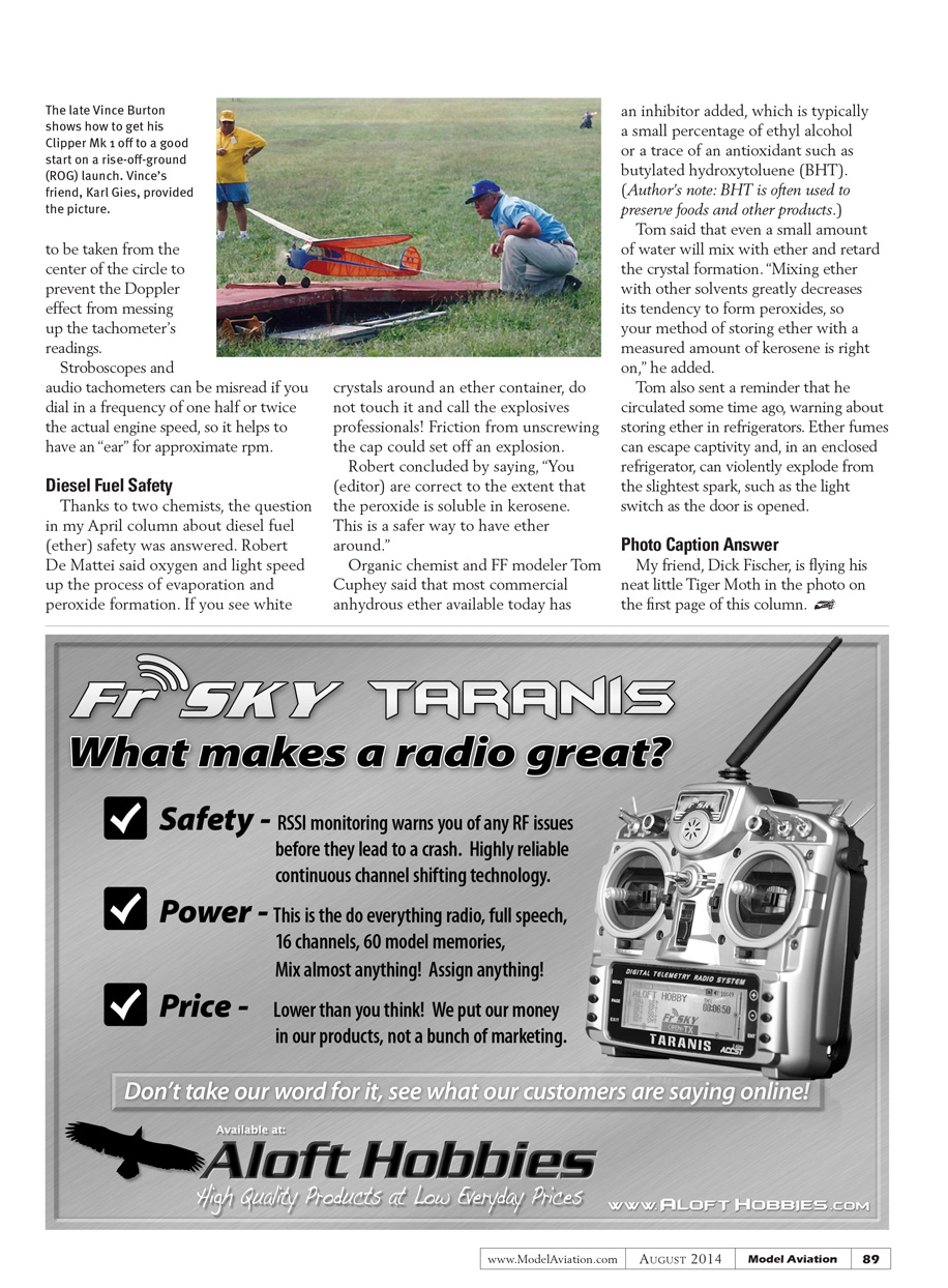
The late Vince Burton shows how to get his Clipper Mk I off to a good start on a rise-off-ground (ROG) launch. Vince’s friend, Karl Giles, provided the picture.
Stroboscopes and audio tachometers can be misread if you dial in a frequency of one half or twice the actual engine speed, so it helps to have an “ear” for approximate rpm.
Diesel Fuel Safety
Thanks to two chemists, the question in my April column about diesel fuel (ether) safety was answered. Robert De Mattei said oxygen and light speed up the process of evaporation and peroxide formation. If you see white crystals around an ether container, do not touch it and call the explosives professionals! Friction from unscrewing the cap could set off an explosion.
Robert concluded by saying, “You (editor) are correct to the extent that the peroxide is soluble in kerosene. This is a safer way to have ether around.”
Organic chemist and FF modeler Tom Cuphey said that most commercial anhydrous ether available today has an inhibitor added, which is typically a small percentage of ethyl alcohol or a trace of an antioxidant such as butylated hydroxytoluene (BHT). (Author’s note: BHT is often used to preserve foods and other products.)
Tom said that even a small amount of water will mix with ether and retard the crystal formation. “Mixing ether with other solvents greatly decreases its tendency to form peroxides, so your method of storing ether with a measured amount of kerosene is right on,” he added.
Tom also sent a reminder that he circulated some time ago, warning about storing ether in refrigerators. Ether fumes can escape captivity and, in an enclosed refrigerator, can violently explode from the slightest spark, such as the light switch as the door is opened.
Photo Caption Answer
My friend, Dick Fischer, is flying his neat little Tiger Moth in the photo on the first page of this column.
Transcribed from original scans by AI. Minor OCR errors may remain.

