
From twin pushers to Pylon models
Bob Angell | [email protected]
TWIN-PUSHER rubber designs dominated early modeling competition. Later, Vernon Boehle and others showed that single-motor, rubber-powered airplanes could also be competitive.
In the early quest for performance, little attempt was made to copy full-scale aircraft. Then, as gasoline power became practical, more models began to sport a scale-like appearance, including cabins and windows in their design.
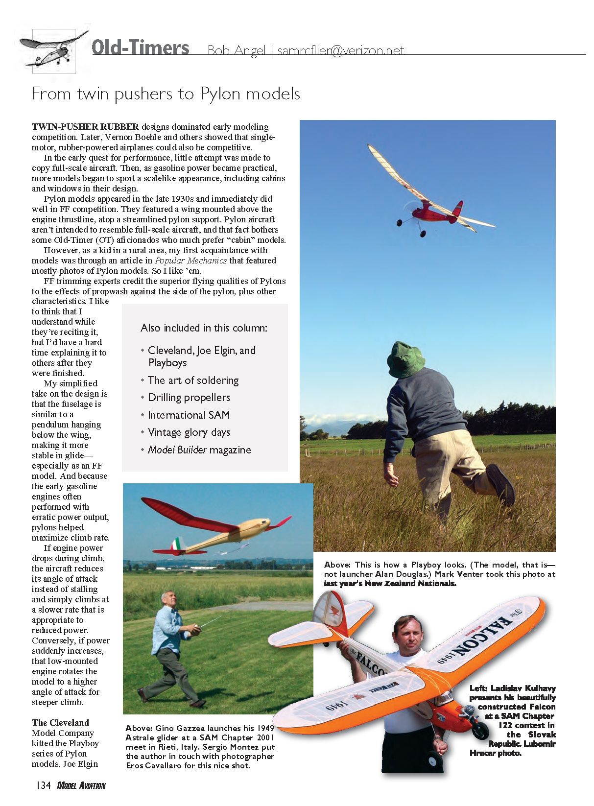
Pylon models appeared in the late 1930s and immediately did well in free-flight (FF) competition. They featured a wing mounted above the engine thrustline, atop a streamlined pylon support. Pylon aircraft aren't intended to resemble full-scale aircraft, and that fact bothers some Old-Timer (OT) aficionados who much prefer "cabin" models. However, as a kid in a rural area, my first acquaintance with models was through an article in Popular Mechanics that featured mostly photos of Pylon models. So I like 'em.
FF trimming experts credit the superior flying qualities of Pylons to the effects of propwash against the side of the pylon, plus other characteristics. I like to think that I understand while they're reciting it, but I'd have a hard time explaining it to others after they were finished.
My simplified take on the design is that the fuselage is similar to a pendulum hanging below the wing, making it more stable in glide—especially as an FF model. And because the early gasoline engines often performed with erratic power output, pylons helped maximize climb rate. If engine power drops during climb, the aircraft reduces its angle of attack instead of stalling and simply climbs at a slower rate that is appropriate to reduced power. Conversely, if power suddenly increases, that low-mounted engine rotates the model to a higher angle of attack for steeper climb.
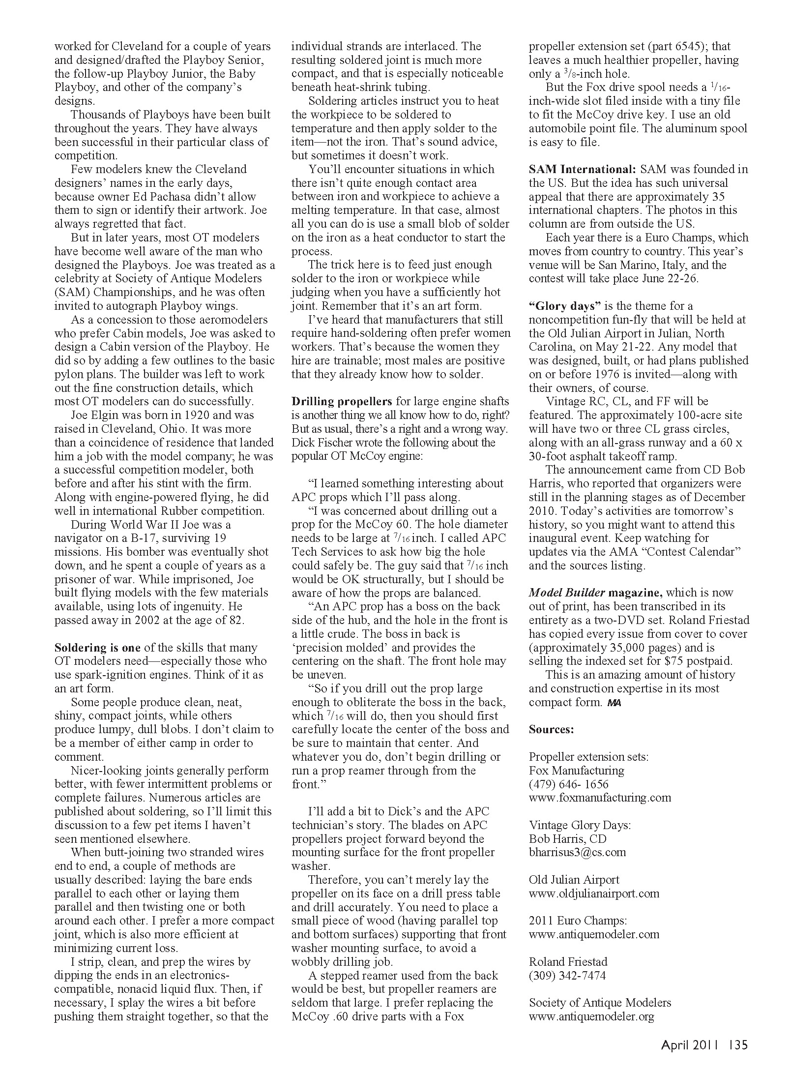
The Cleveland Model Company kitted the Playboy series of Pylon models. Joe Elgin worked for Cleveland for a couple of years and designed/drafted the Playboy Senior, the follow-up Playboy Junior, the Baby Playboy, and other of the company's designs. Thousands of Playboys have been built throughout the years. They have always been successful in their particular class of competition. Few modelers knew the Cleveland designers' names in the early days, because owner Ed Pachasa didn't allow them to sign or identify their artwork. Joe always regretted that fact. But in later years, most OT modelers have become well aware of the man who designed the Playboys. Joe was treated as a celebrity at Society of Antique Modelers (SAM) Championships, and he was often invited to autograph Playboy wings. As a concession to those aeromodelers who prefer cabin models, Joe was asked to design a cabin version of the Playboy. He did so by adding a few outlines to the basic pylon plans. The builder was left to work out the fine construction details, which most OT modelers can do successfully.
Joe Elgin was born in 1920 and was raised in Cleveland, Ohio. It was more than a coincidence of residence that landed him a job with the model company; he was a successful competition modeler, both before and after his stint with the firm. Along with engine-powered flying, he did well in international rubber competition. During World War II Joe was a navigator on a B-17, surviving 19 missions. His bomber was eventually shot down, and he spent a couple of years as a prisoner of war. While imprisoned, Joe built flying models with the few materials available, using lots of ingenuity. He passed away in 2002 at the age of 82.
Soldering is one of the skills that many OT modelers need—especially those who use spark-ignition engines. Think of it as an art form.
Some people produce clean, neat, shiny, compact joints, while others produce lumpy, dull blobs. I don't claim to be a member of either camp in order to comment.
Nicer-looking joints generally perform better, with fewer intermittent problems or complete failures. Numerous articles are published about soldering, so I'll limit this discussion to a few pet items I haven't seen mentioned elsewhere.
When butt-joining two stranded wires end to end, a couple of methods are usually described: laying the bare ends parallel to each other or laying them parallel and then twisting one or both around each other. I prefer a more compact joint, which is also more efficient at minimizing current loss.
I strip, clean, and prep the wires by dipping the ends in an electronics-compatible, nonacid liquid flux. Then, if necessary, I splay the wires a bit before pushing them straight together, so that the individual strands are interlaced. The resulting soldered joint is much more compact, and that is especially noticeable beneath heat-shrink tubing.
Soldering articles instruct you to heat the workpiece to be soldered to temperature and then apply solder to the item—not the iron. That's sound advice, but sometimes it doesn't work.
You'll encounter situations in which there isn't quite enough contact area between iron and workpiece to achieve a melting temperature. In that case, almost all you can do is use a small blob of solder on the iron as a heat conductor to start the process.
The trick here is to feed just enough solder to the iron or workpiece while judging when you have a sufficiently hot joint. Remember that it's an art form.
I've heard that manufacturers that still require hand-soldering often prefer women workers. That's because the women they hire are trainable; most males are positive that they already know how to solder.
Drilling propellers
Drilling propellers for large engine shafts is another thing we all know how to do, right? But as usual, there's a right and a wrong way. Dick Fischer wrote the following about the popular OT McCoy engine:
"I learned something interesting about APC props which I'll pass along.
"I was concerned about drilling out a prop for the McCoy .60. The hole diameter needs to be large at 7/16 inch. I called APC Tech Services to ask how big the hole could safely be. The guy said that 7/16 inch would be OK structurally, but I should be aware of how the props are balanced.
"An APC prop has a boss on the back side of the hub, and the hole in the front is a little crude. The boss in back is 'precision molded' and provides the centering on the shaft. The front hole may be uneven.
"So if you drill out the prop large enough to obliterate the boss in the back, which 7/16 will do, then you should first carefully locate the center of the boss and be sure to maintain that center. And whatever you do, don't begin drilling or run a prop reamer through from the front."
I'll add a bit to Dick's and the APC technician's story. The blades on APC propellers project forward beyond the mounting surface for the front propeller washer.
Therefore, you can't merely lay the propeller on its face on a drill press table and drill accurately. You need to place a small piece of wood (having parallel top and bottom surfaces) supporting that front washer mounting surface, to avoid a wobbly drilling job.
A stepped reamer used from the back would be best, but propeller reamers are seldom that large. I prefer replacing the McCoy .60 drive parts with a Fox propeller extension set (part 6545); that leaves a much healthier propeller, having only a 3/8-inch hole.
But the Fox drive spool needs a 1/16-inch-wide slot filed inside with a tiny file to fit the McCoy drive key. I use an old automobile point file. The aluminum spool is easy to file.
SAM International
SAM was founded in the U.S., but the idea has such universal appeal that there are approximately 35 international chapters. The photos in this column are from outside the U.S.
Each year there is a Euro Champs, which moves from country to country. This year's venue will be San Marino, Italy, and the contest will take place June 22–26.
"Glory Days" is the theme for a noncompetition fun-fly that will be held at the Old Julian Airport in Julian, North Carolina, on May 21–22. Any model that was designed, built, or had plans published on or before 1976 is invited—along with their owners, of course.
Vintage RC, CL, and FF will be featured. The approximately 100-acre site will have two or three CL grass circles, along with an all-grass runway and a 60 x 30-foot asphalt takeoff ramp.
The announcement came from CD Bob Harris, who reported that organizers were still in the planning stages as of December 2010. Today's activities are tomorrow's history, so you might want to attend this inaugural event. Keep watching for updates via the AMA "Contest Calendar" and the sources listing.
Model Builder magazine
Model Builder magazine, which is now out of print, has been transcribed in its entirety as a two-DVD set. Roland Friestad has copied every issue from cover to cover (approximately 35,000 pages) and is selling the indexed set for $75 postpaid.
This is an amazing amount of history and construction expertise in its most compact form. MA
Sources
- Propeller extension sets:
Fox Manufacturing (479) 646-1656 www.foxmanufacturing.com
- Vintage Glory Days:
Bob Harris, CD [email protected]
- Old Julian Airport:
- 2011 Euro Champs:
- Roland Friestad:
(309) 342-7474
- Society of Antique Modelers:
Transcribed from original scans by AI. Minor OCR errors may remain.

