
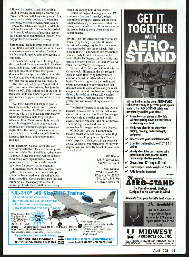
Osprey
Bill Winter / John Hunton
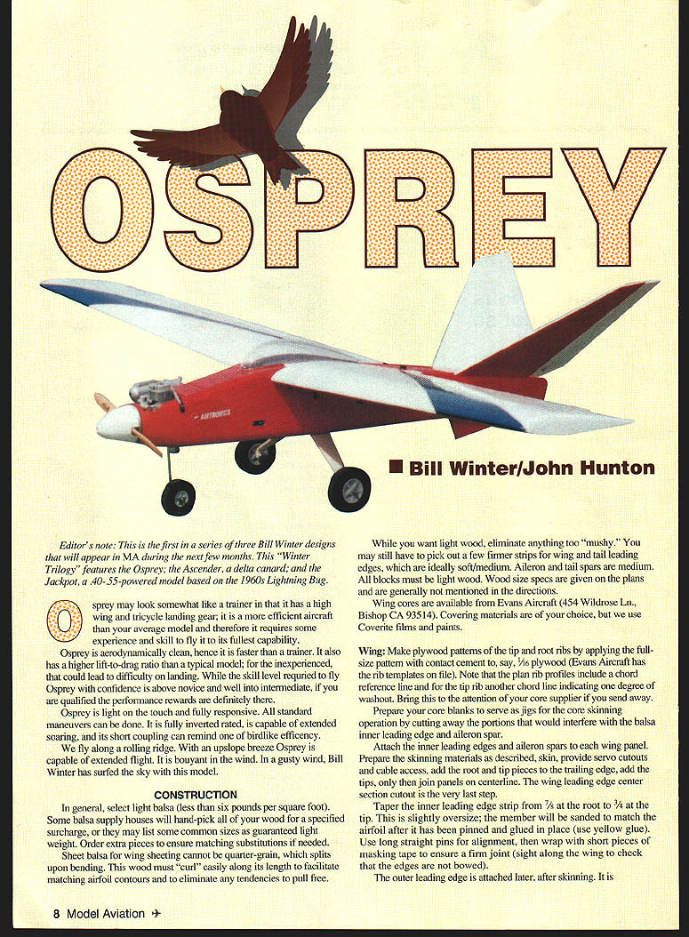
Editor's note: This is the first in a series of three Bill Winter designs that will appear in MA during the next few months. This "Winter Trilogy" features the Osprey, the Ascender (a delta canard), and the Jackpot (a .40–.35–powered model based on the 1960s Lightning Bug).
Osprey may look somewhat like a trainer because of its high wing and tricycle landing gear, but it is a more efficient aircraft than your average model and therefore requires some experience and skill to get the most from it. Aerodynamically clean, Osprey is faster than a trainer and has a higher lift-to-drag ratio; for the inexperienced that can make landings more challenging. The skill level required is above novice and into intermediate, but the performance rewards are worth it.
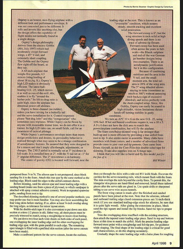
Osprey is light on the controls and fully responsive. All standard maneuvers can be flown; it is fully inverted-rated, capable of extended soaring, and its short coupling gives a birdlike efficiency. On a rolling ridge with an upslope breeze Osprey can soar for extended periods and is buoyant in wind. In gusty conditions it has been successfully surfed by Bill Winter.
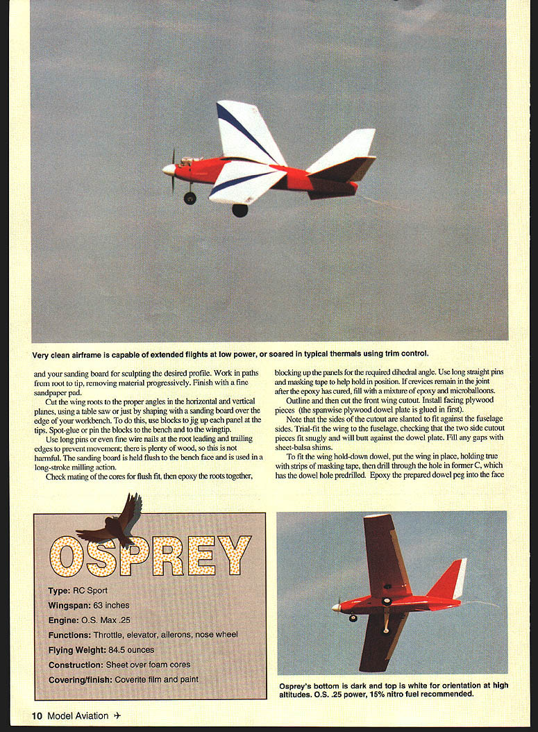
Specifications
- Type: RC Sport
- Wingspan: 63 inches
- Engine: O.S. Max .25
- Functions: Throttle, elevator, ailerons, nose wheel
- Flying weight: 84.5 ounces
- Construction: Sheet over foam cores
- Covering/finish: Coverite film and paint
Construction
Materials and general
- Select light balsa: less than 6 lb/ft³. Some suppliers will hand‑pick wood for a surcharge; order extras to allow matching substitutions.
- Do not use quarter‑grain sheet balsa for wing sheeting (it splits on bending). Sheet must curl easily along its length to match airfoil contours without pulling free.
- Leading edges: soft/medium; aileron and tail spars: medium. All blocks should be light wood.
- Wing cores are available from Evans Aircraft (454 Wildrose Ln., Bishop, CA 93514).
- Covering: Coverite films and paint recommended.
Wing — overview and cores
- Make plywood patterns for tip and root ribs: apply full‑size patterns to 1/16" plywood with contact cement. (Evans Aircraft has rib templates on file.)
- Note the plan rib profiles: the chord reference line and the tip rib's washout line—inform your core supplier if sending cores out.
- Prepare core blanks as jigs for skinning; cut away portions that would interfere with the balsa inner leading edge and aileron spar.
- Attach the inner leading edge and aileron spar to each wing panel before skinning.
Taper the inner leading edge from 7/8" at the root to 3/4" at the tip. Leave it slightly oversize; sand to the airfoil after pinning and gluing (yellow glue). Use long straight pins for alignment and short masking‑tape wraps to ensure a firm joint. Sight along the wing to check for bows. The outer leading edge is attached after skinning.
The aileron (rear) spar is pre‑tapered to allow block sanding to fit the foam. Block‑sand edges to the airfoil contours shown on the plans.
Wing skinning and servo cutouts
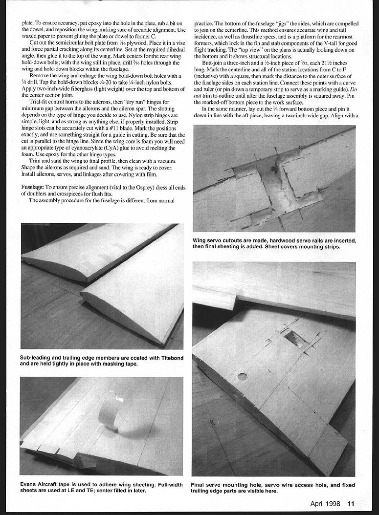
- Before skinning, sand the aileron spar and inner leading edge on a sanding board: a plywood board with attached sandpaper using spray contact adhesive. Work repeated spanwise paths from root to tip.
- Skinning approach (one recommended method):
- Allow at least 1/4" overlap along long edges to tolerate minor layout errors.
- Use double‑stick tape to hold one skin section at a time (12 sections total).
- Put down two 4"‑wide sheets on both sides of each panel: one overlapping the inner leading edge, the other overlapping the trailing-edge spar, grain parallel to the edge.
- Fill the remaining open triangle with a prefitted skin section after servo cutouts are made.
- Make cardboard patterns for servo cutouts, locate outlines, and cut through skins with a No. 11 blade. Excavate cavities for servo mounting rails so servos mount flush. The foam skin may overlap rails beyond the cavity lines; hand‑fit and remove triangular skin pieces, then install them after the rails are glued.
- Use spade drills or sharpened tubing to cut servo wire access tunnels.
Centerline, tip blocks, and leading edge shaping
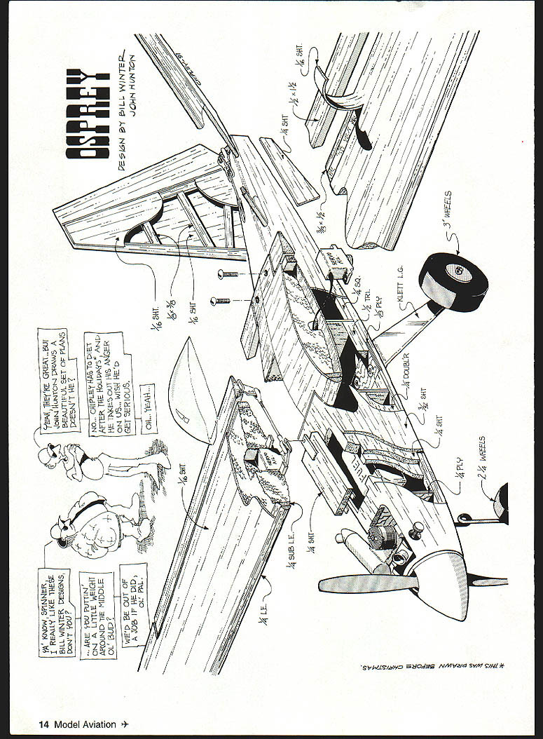
- Join panels on the centerline only after skins, root, and tip trailing edge pieces are installed. The wing leading-edge center‑section cutout is the last step.
- The inboard and outboard trailing edge (ailerons) are cut as extension pieces of 1/2" stock; if using standard TE stock for ailerons, choose very light wood. After gluing the extensions, block sand tips square and install tip blocks, sanding to the proper profile.
- Trim overlapping skins flush, then attach the tapered outer leading edge. Sand top and bottom faces to match the airfoil. Mark the leading-edge forward point with a straightedge and felt‑tip for shaping guidance.
- Shape the outer leading edge roughly with a balsa plank, then finish with sanding blocks and fairing strips until the core-to-leading-edge transition is smooth. Carve root fillets after the outer leading edge is glued and sanded.
Ailerons and hinges
- Make ailerons from 1/8" sheet balsa with 1/8" spars and leading‑edge stock; taper the trailing edge to a sharp knife edge. Balance with small weights if necessary. Prototype ailerons were 3/16" film covered.
- Cut aileron cutouts after final contouring. Install hinge blocks and reinforce hinge areas with fiberglass or light‑ply doublers.
- Hinge options: nylon strip hinges are light and strong if installed properly. Use the #11 blade and a straight guide to cut accurate hinge slots. For other hinge types use epoxy; for strip hinges use an appropriate CYA for foam compatibility (avoid foammelting cyanoacrylates).
Center section, hold‑down, and reinforcement
- Fit the front wing cutout after finished and sanded panels are joined at the root.
- Trial‑fit the wing to the fuselage and ensure side cutout pieces fit snugly against the spanwise plywood dowel plate. Fill gaps with sheet‑balsa shims.
- For the hold‑down dowel:
- With the wing positioned true, drill through the hole in former C (predrilled). Epoxy the prepared dowel peg into the face of the dowel plate; when dry sand smooth and finish with a fillet of epoxy and microballoons.
- Install a 1/16" plywood plate on the inside face of the wing in the cutout area and install glue‑in blind nuts for hold‑down bolts.
- Cut the semicircular bolt plate from 1/16" plywood, force partial cracking along the centerline in a vise, set at required dihedral, then glue to the top of the wing. Mark centers for rear hold‑down bolts and drill 7/16" holes through wing and hold‑down blocks inside the fuselage. Remove wing, enlarge bolt holes with 1/4" drill, and tap hold‑down blocks 1/4‑20 for 1/4" nylon bolts. Apply 2"‑wide light fiberglass over top and bottom of center section joint.
Final wing finishing
- Trial‑fit control horns and "dry run" hinges for trim. Form the hinge gap appropriate for the hinge type.
- Trim and sand the wing to final profile; vacuum clean the surfaces. Shape ailerons as required and sand them. Cover with film, then install servos and linkages.
Fuselage
Philosophy and alignment
- Precise alignment is vital. The fuselage is assembled using the bottom sheet as the jig to force the sides to join on the centerline; this insures accurate wing and tail incidence and thrustline, and locks in V‑tail geometry.
- The top‑view on the plans is actually looking down onto the bottom and shows structural locations.
Preparations
- Butt‑join a 2" and a 1/2" piece of 3/32" each 2‑1/2" long; mark the centerline and station locations C to F with a square and mark distances to the outer surface of the fuselage sides. Connect points with a curve and use this as a guide. Pin the marked bottom to the work surface.
- Lay out fuselage sides from 36" lengths of 3/32" balsa, duplicating the plan outline. Keep edges straight; butt‑join sheets as necessary.
- Use the straight bottom line to scribe upright positions and trim to outline. Trace outer outlines onto side blanks, pin sides together, and sand outlines to conform. Mark L or R on the inside faces.
Assembly
- Locate longerons, doublers, crosspieces, etc. (except forward of the firewall) on each side frame; check width of slots for firewall and former C with scrap wood. Cut firewall and all formers. Cut the 1/4 sheet fill pieces at the V‑tail seat precisely (note plan elevation).
- Drill firewall holes for blind nuts, fuel lines, and linkages. Install blind nuts for combined engine/gear mount.
- Install formers B, C, and D on one side frame, checking snugness and 90° fit using a triangle. Dry fit to the opposite side.
- Rest structure on bench, checking full‑length alignment with no daylight between bench and frame before using CYA or yellow glue.
- Cut plywood landing gear plate to fit; mark/drill screw holes and install blind nuts. Glue plate and triangular side corner pieces per plans. Cut bottom crosspieces to length over plan, allowing 1/4" plus 3/32" for side thickness aft of the landing gear and at station C, add an extra 1/4" for doubler thickness.
- Pin partially assembled sides to the bottom sheet as far aft as station D and glue.
- Before joining the sides at the rear, install mid‑cabin crosspiece, hardwood servo rails, and hold‑down block (prevents distortion when bending sides).
- Join sides at the rear, pinning then gluing from station D to the tail. To ease bending, moisten the local area and cut tiny wedges or make Zona saw cuts into the inner face of longerons where needed.
- Glue 1/4" sheet pieces E, F, and G in place to the bottom and to the rear faces of the bottom crosspieces.
- To pull sides square at the top for gluing, use clamps with plywood protection on sides. Before closing the fuselage top, locate the wing (per wing construction) and drill dowel holes. Add two top crosspieces forward of the tail surfaces.
Tank compartment, nose, and final shaping
- Fuelproof the tank compartment with epoxy. Complete tank, steering arm, and linkage installations.
- Glue in nose laminations forward of the firewall. Sand the front of the nose for even fit with nose plywood ring A.
- Temporarily mount the engine and spinner backplate to trace spinner plate outline as a guide for former A location.
- Use a #11 blade to slope rear longerons to 45° where required for tail mounting.
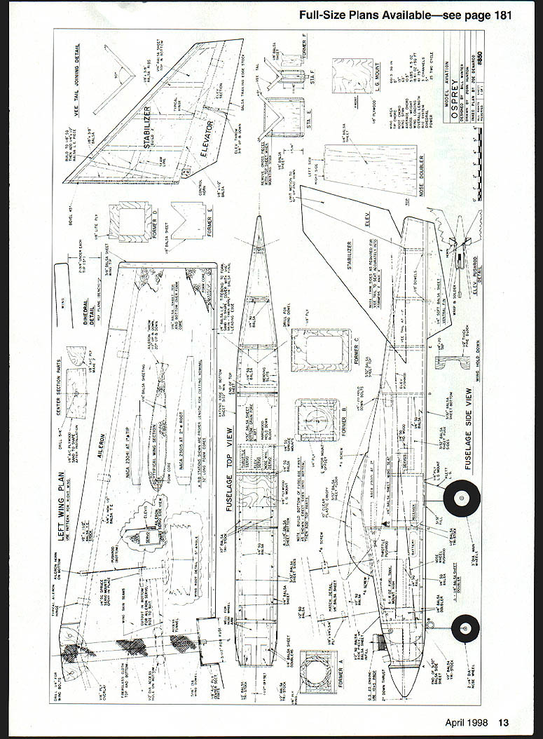
- Trim the wing saddle for a close fit (match wing dihedral slope). Make the elevator pushrod assembly before sheeting the rear fuselage top.
- Sheet the nose top fore and aft of the hatch ends (1/2" square side top corner pieces extend beyond the firewall to former A).
- Spot‑glue the tank hatch in place; match contours during fuselage sanding. Rough‑shape nose contours with a coarse sanding block and finish with finer pads.
Controls and hardware
- Make aileron torque rods from 1/8" music wire, fit to servos, and use clevises/quick‑link hardware for easy removal. Control runs use conventional nylon‑sheathed cable; provide ample slack and service loops.
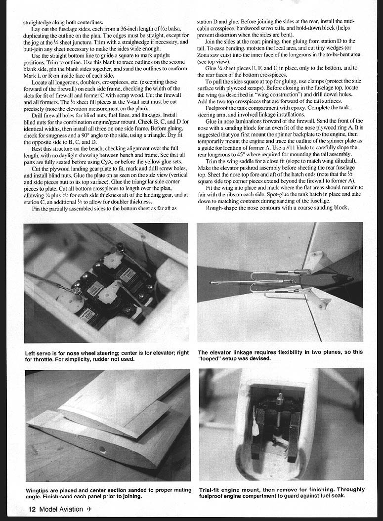
- Mount engine, landing gear, and radio gear (Airtronics recommended). Check balance at the shown CG and adjust battery pack or add ballast. Also check lateral balance.
Flying
- Takeoff: Osprey is light on its wheels and may fly before you expect. For initial flights let it roll with neutral elevator, then gently fly it off—do not yank.
- Keep it close on early flights until comfortable with its in‑air appearance and handling. High efficiency makes thermalling and soaring easy and means it does not descend quickly; compensate accordingly.
- At L/D speed the model is stable and stalls gently, mushing ahead rather than dropping into a spin.
- Landing: be prepared to circle or extend final to lose altitude. Aim to get the wheels onto the ground to kill excess speed and avoid running out of runway. Practice high, simulated approaches to build confidence.
Osprey is a unique, efficient model you will enjoy flying. Let the designers know of your successes.
Bill Winter 12811 Melville Ln Fairfax, VA 22033
John Hunton 9154 Rixeyville Rd. Rixeyville, VA 22737 (H) (540) 937‑3545 (W) (703) 874‑4486
Transcribed from original scans by AI. Minor OCR errors may remain.

