
P-40 Warhawk
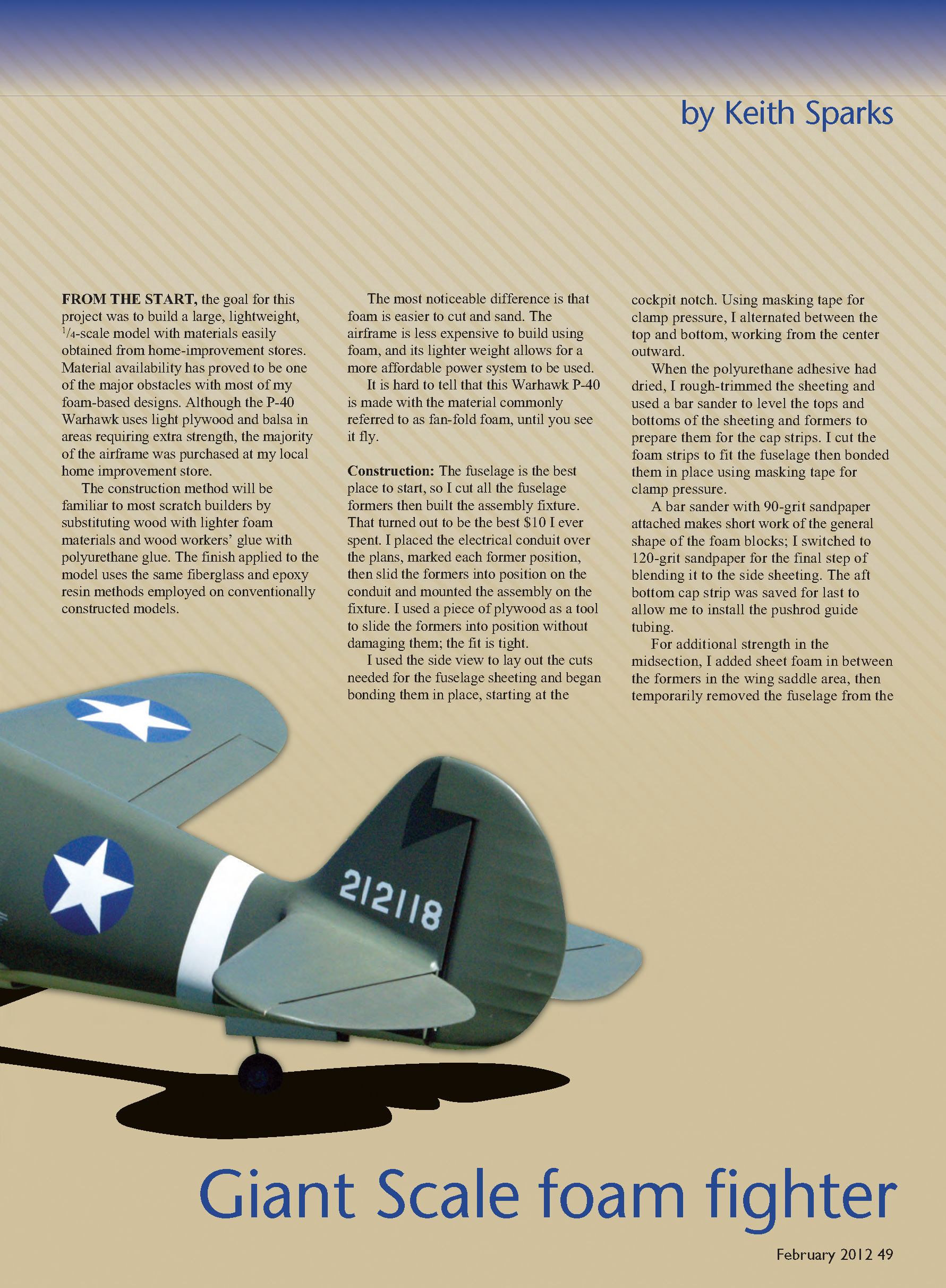
by Keith Sparks
From the start, the goal for this project was to build a large, lightweight, 1/4-scale model with materials easily obtained from home-improvement stores. Material availability has proved to be one of the major obstacles with most of my foam-based designs. Although the P-40 Warhawk uses light plywood and balsa in areas requiring extra strength, the majority of the airframe was purchased at my local home improvement store.
The construction method will be familiar to most scratch builders by substituting wood with lighter foam materials and woodworkers' glue with polyurethane glue. The finish applied to the model uses the same fiberglass and epoxy resin methods employed on conventionally constructed models.
The most noticeable difference is that foam is easier to cut and sand. The airframe is less expensive to build using foam, and its lighter weight allows for a more affordable power system to be used. It is hard to tell that this Warhawk P-40 is made with the material commonly referred to as fan-fold foam until you see it fly.
Construction
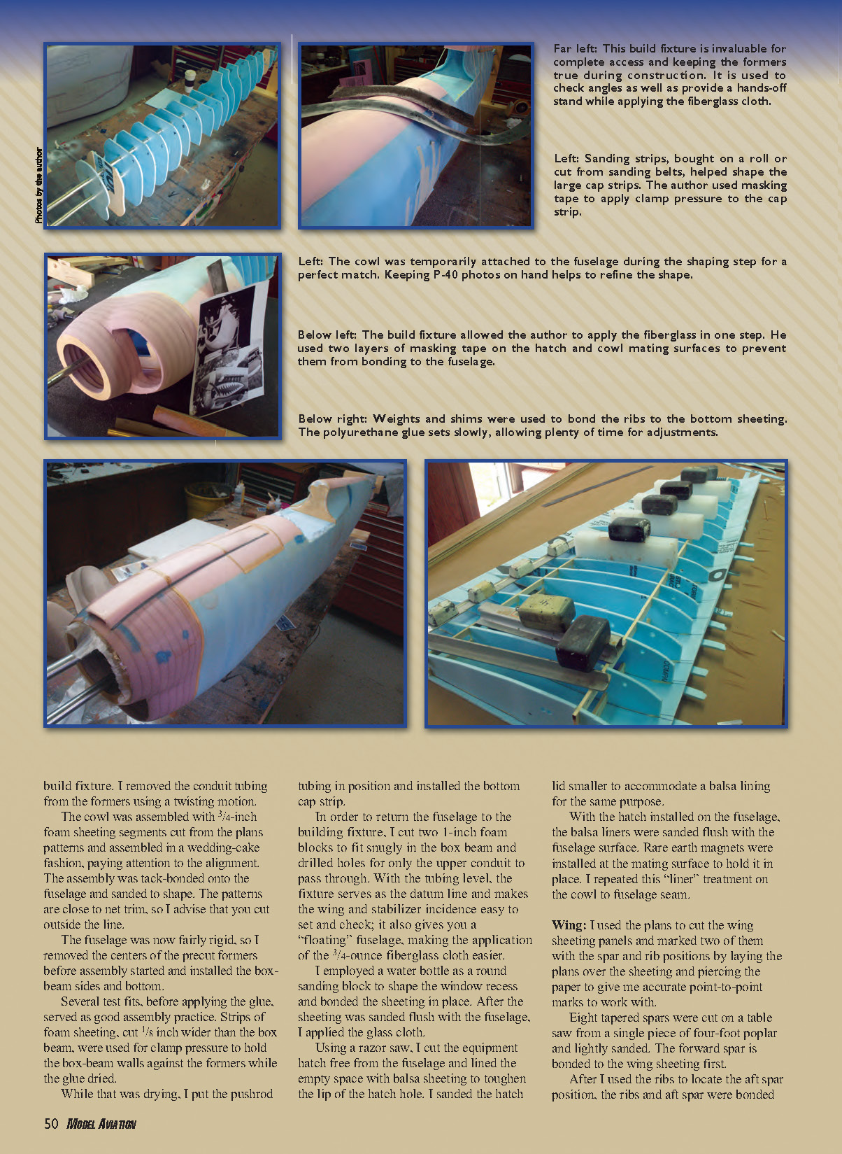
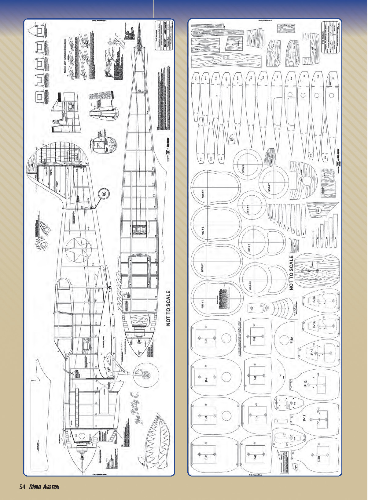
The fuselage is the best place to start. I cut all the fuselage formers then built the assembly fixture—one of the best $10 I ever spent. I placed the electrical conduit over the plans, marked each former position, slid the formers into position on the conduit, and mounted the assembly on the fixture. I used a piece of plywood as a tool to slide the formers into position without damaging them; the fit is tight.
I used the side view to lay out the cuts needed for the fuselage sheeting and began bonding them in place, starting at the cockpit notch. Using masking tape for clamp pressure, I alternated between the top and bottom, working from the center outward.
When the polyurethane adhesive had dried, I rough-trimmed the sheeting and used a bar sander to level the tops and bottoms of the sheeting and formers to prepare them for the cap strips. I cut the foam strips to fit the fuselage then bonded them in place using masking tape for clamp pressure.
A bar sander with 90-grit sandpaper attached makes short work of the general shape of the foam blocks; I switched to 120-grit sandpaper for the final step of blending them to the side sheeting. The aft bottom cap strip was saved for last to allow installation of the pushrod guide tubing.
For additional strength in the midsection, I added sheet foam between the formers in the wing-saddle area, then temporarily removed the fuselage from the build fixture. I removed the conduit tubing from the formers using a twisting motion. The cowl was assembled with 3/4-inch foam sheeting segments cut from the plan patterns and assembled in a wedding-cake fashion, paying attention to alignment. The assembly was tack-bonded onto the fuselage and sanded to shape. The patterns are close to net-trim, so cut outside the line.
The fuselage was now fairly rigid, so I removed the centers of the precut formers before final assembly and installed the box-beam sides and bottom. Several test fits before applying glue served as good assembly practice. Strips of foam sheeting, cut 1/8 inch wider than the box beam, were used for clamp pressure to hold the box-beam walls against the formers while the glue dried.
While that was drying, I put the pushrod tubing in position and installed the bottom cap strip.
To return the fuselage to the building fixture, I cut two 1-inch foam blocks to fit snugly in the box beam and drilled holes for only the upper conduit to pass through. With the tubing level, the fixture serves as the datum line and makes the wing and stabilizer incidence easy to set and check; it also gives you a "floating" fuselage, making the application of the 3/4-ounce fiberglass cloth easier.
I employed a water bottle as a round sanding block to shape the window recess and bonded the sheeting in place. After the sheeting was sanded flush with the fuselage, I applied the glass cloth.
Using a razor saw, I cut the equipment hatch free from the fuselage and lined the empty space with balsa sheeting to toughen the lip of the hatch hole. I sanded the hatch lid smaller to accommodate a balsa lining for the same purpose.
With the hatch installed on the fuselage, the balsa liners were sanded flush with the fuselage surface. Rare-earth magnets were installed at the mating surface to hold it in place. I repeated this liner treatment on the cowl-to-fuselage seam.
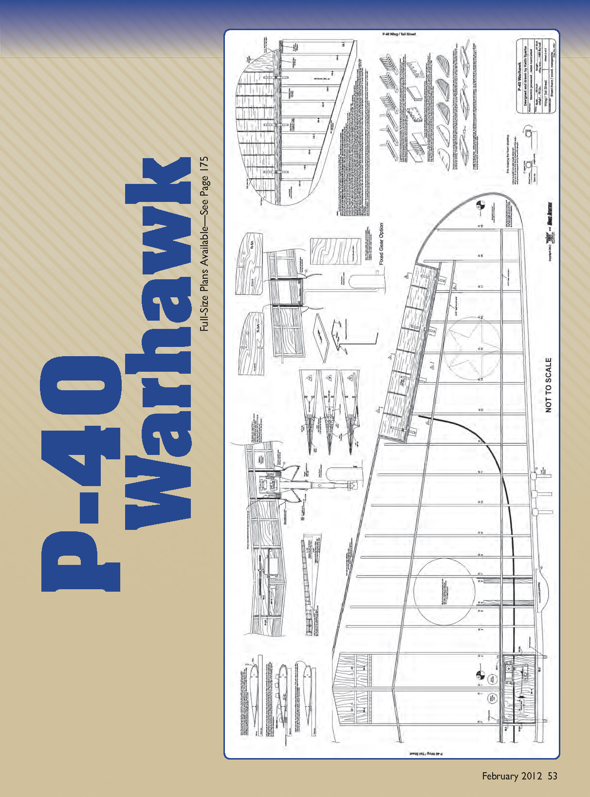
Wing
I used the plans to cut the wing sheeting panels and marked two of them with the spar and rib positions by laying the plans over the sheeting and piercing the paper to give accurate point-to-point marks.
Eight tapered spars were cut on a table saw from a single four-foot piece of poplar and lightly sanded. The forward spar is bonded to the wing sheeting first.
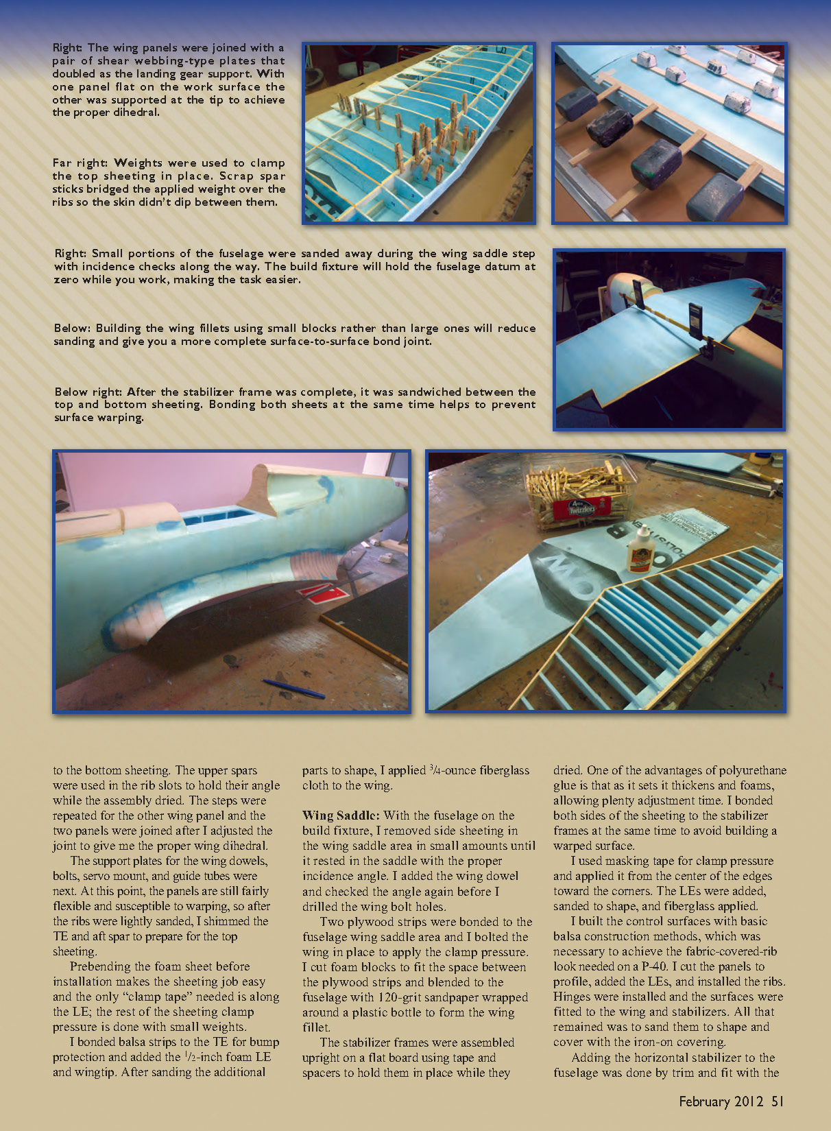
After I used the ribs to locate the aft spar position, the ribs and aft spar were bonded to the bottom sheeting with weights and shims. The polyurethane glue sets slowly, allowing plenty of time for adjustments. The upper spars were used in the rib slots to hold their angle while the assembly dried. The steps were repeated for the other wing panel and the two panels were joined after I adjusted the joint to give the proper wing dihedral.
Next came the support plates for the wing dowels, bolts, servo mount, and guide tubes. At this point the panels are still fairly flexible and susceptible to warping, so after the ribs were lightly sanded I shimmed the TE and aft spar to prepare for the top sheeting.
Prebending the foam sheet before installation makes the sheeting job easy; the only clamp tape needed is along the leading edge—the rest of the sheeting clamp pressure is done with small weights.
I bonded balsa strips to the TE for bump protection and added the 1/2-inch foam LE and wingtip. After sanding the additional parts to shape, I applied 3/4-ounce fiberglass cloth to the wing.
Wing Saddle
With the fuselage on the build fixture, I removed side sheeting in the wing-saddle area in small amounts until the wing rested in the saddle with the proper incidence angle. I added the wing dowel and checked the angle again before drilling the wing-bolt holes.
Two plywood strips were bonded to the fuselage wing-saddle area and I bolted the wing in place to apply clamp pressure. I cut foam blocks to fit the space between the plywood strips and blended them to the fuselage with 120-grit sandpaper wrapped around a plastic bottle to form the wing fillet.
The stabilizer frames were assembled upright on a flat board using tape and spacers to hold them while they dried. One advantage of polyurethane glue is that as it sets it thickens and foams, allowing plenty of adjustment time. I bonded both sides of the sheeting to the stabilizer frames at the same time to avoid building a warped surface.
I used masking tape for clamp pressure and applied it from the center of the edges toward the corners. The LEs were added, sanded to shape, and fiberglass was applied.
I built the control surfaces with basic balsa construction methods to achieve the fabric-covered-rib look needed on a P-40. I cut the panels to profile, added the LEs, and installed the ribs. Hinges were installed and the surfaces were fitted to the wing and stabilizers. All that remained was to sand them to shape and cover with iron-on covering.
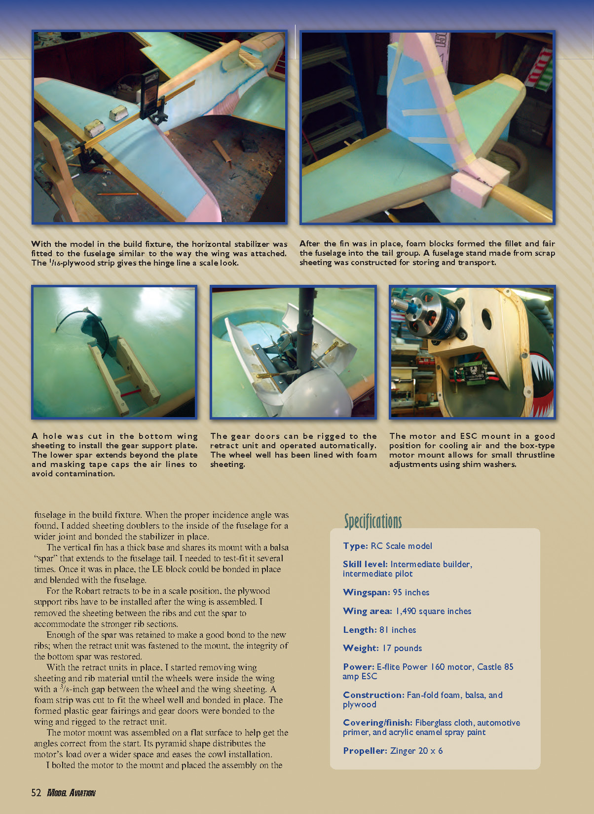
Adding the horizontal stabilizer to the fuselage was done by trim-and-fit with the fuselage in the build fixture. When the proper incidence angle was found, I added sheeting doublers to the inside of the fuselage for a wider joint and bonded the stabilizer in place.
The vertical fin has a thick base and shares its mount with a balsa "spar" that extends to the fuselage tail. I test-fit it several times. Once in place, the LE block was bonded in place and blended with the fuselage.
For the Robart retracts to be in a scale position, the plywood support ribs have to be installed after the wing is assembled. I removed the sheeting between the ribs and cut the spar to accommodate the stronger rib sections. Enough of the spar was retained to make a good bond to the new ribs; when the retract unit was fastened to the mount, the integrity of the bottom spar was restored.
With the retract units in place, I removed wing sheeting and rib material until the wheels were inside the wing with a 3/16-inch gap between the wheel and the wing sheeting. A foam strip was cut to fit the wheel well and bonded in place. The formed plastic gear fairings and gear doors were bonded to the wing and rigged to the retract unit.
The motor mount was assembled on a flat surface to help get the angles correct from the start. Its pyramid shape distributes the motor's load over a wider space and eases cowl installation.
I bolted the motor to the mount and placed the assembly on the firewall with the fuselage held vertical. I put the cowl in place and centered the shaft to the cowl using the spinner backplate. I removed the cowl carefully, marked the motor-mount position, and bonded it in place. Small shim washers were used to make minor thrustline adjustments.
Formed Plastic and Finish
A plastic set for this model is available from Park Flyer Plastics. This includes a 6-inch spinner and backplate, gear fairings and doors, cockpit detail, a pilot figure, canopy, cowl flaps, exhaust stacks, and gun blisters.
The plans include a shopping list for materials from Lowe’s; however, you will need to visit a hobby shop for the 3/4-ounce fiberglass cloth and Zap finishing resin as well as the basic RC hardware. I used automotive primer to bring the surface to a smooth finish and acrylic-enamel spray paint to apply the colors and markings.
Equipment
The E-flite 160 motor provides enough power to fly this model with a 20 x 6 propeller; however, you will be pulling the maximum recommended 60 amps.
I chose the Castle 85 amp ESC for its easy programming ability. There is plenty of room for any servo you would likely use; running dual servos for redundancy is the safest route.
I’m using servos with 77 ounces of torque for positive control. The battery compartment is large enough to accommodate any battery size you may want. I’m running 10s, 5,000 mAh lithium cells for longer flight times and better wind penetration.
The Robart rotating retracts used on this design require removing the strut spring and replacing it with one at half the wire diameter for the strut to function properly. This is an intimidating task and likely voids the warranty, so the plans also include patterns to build the model with fixed gear. This option will save you nearly 2 pounds.
Flying
The Warhawk P-40 performs as you would expect, given its light wing loading: shorter takeoff rolls, slower approach speeds, and fly-bys that don’t look like you are being chased. The model pulls to the left on takeoff, but after the tail is off the ground the rudder has positive control. Easing into the throttle makes it predictable and looks true to scale.
Adding flaps to this design would be a waste; at half power the P-40 will give you the control you need and it will set up with a good descent rate. A slight flare at touchdown and cutting the power will give you a roll out of roughly 25 feet.
At 2,100 watts of power, the E-flite 160 will provide enough power for basic flight in 5 to 10 mph winds. A roll requires strict attention to the controls and a loop needs a dive to complete with a sluggish feel at the top.
With my flight program complete, I have found the minimum power requirement for this design. Since the batteries barely get warm after a flight, there is room for more power, so I will be installing a larger motor soon to turn this design into a true warbird.
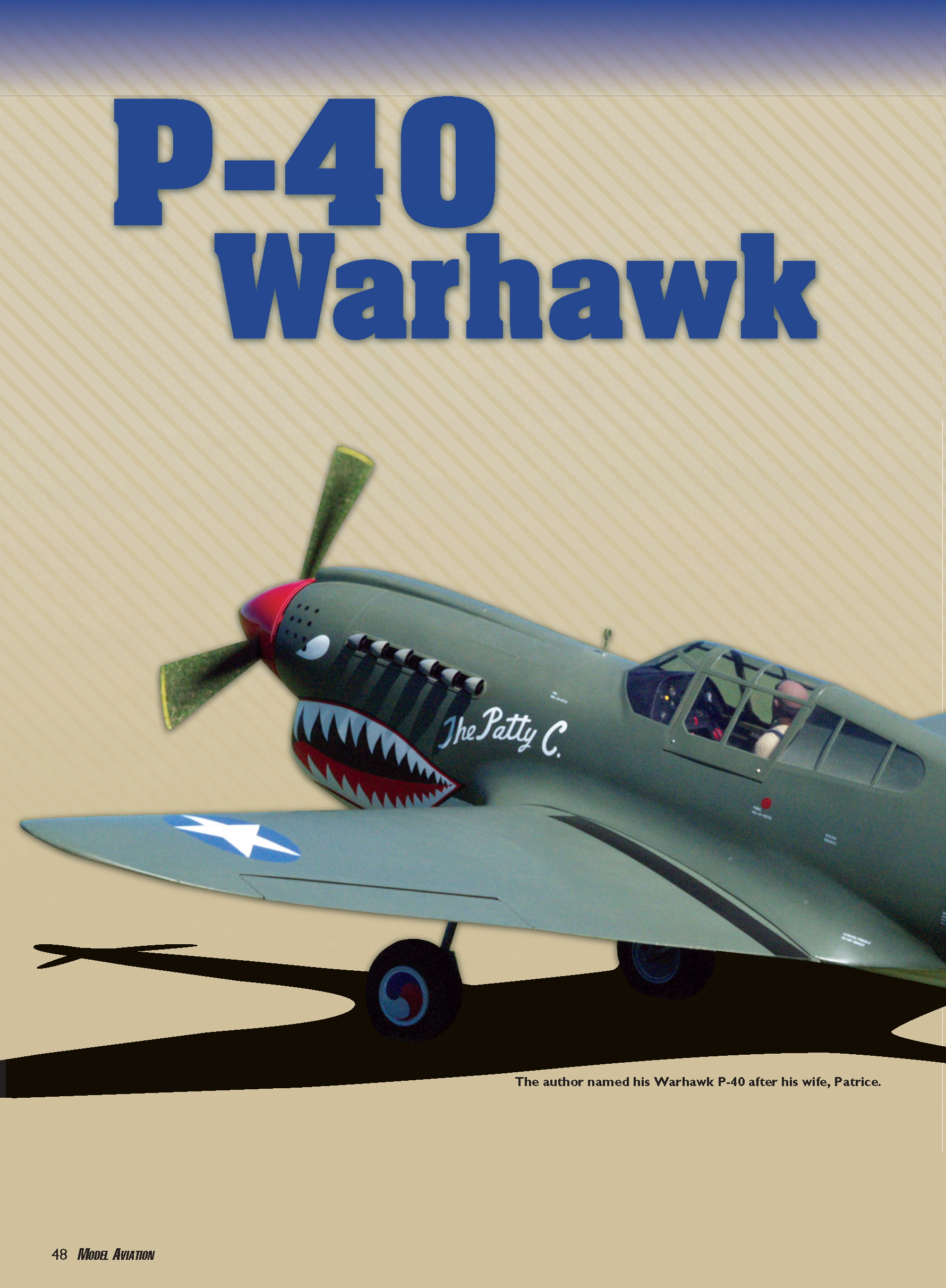
To my wife, Patrice — you have supported me and my hobby for 22 years. This one is for you.
Keith Sparks [email protected]
Sources
- Robart
(630) 584-7616 www.robart.com
- Park Flyer Plastics
(817) 233-1215 www.parkflyerplastics.com
- E-flite
(877) 504-0233 www.e-flite.com
- Castle Creations
(913) 390-6939 www.castlecreations.com
Transcribed from original scans by AI. Minor OCR errors may remain.

