
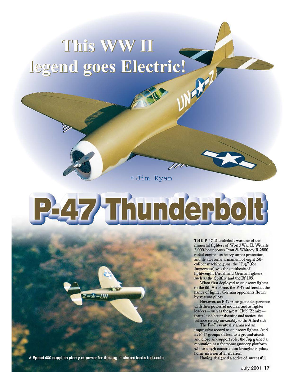
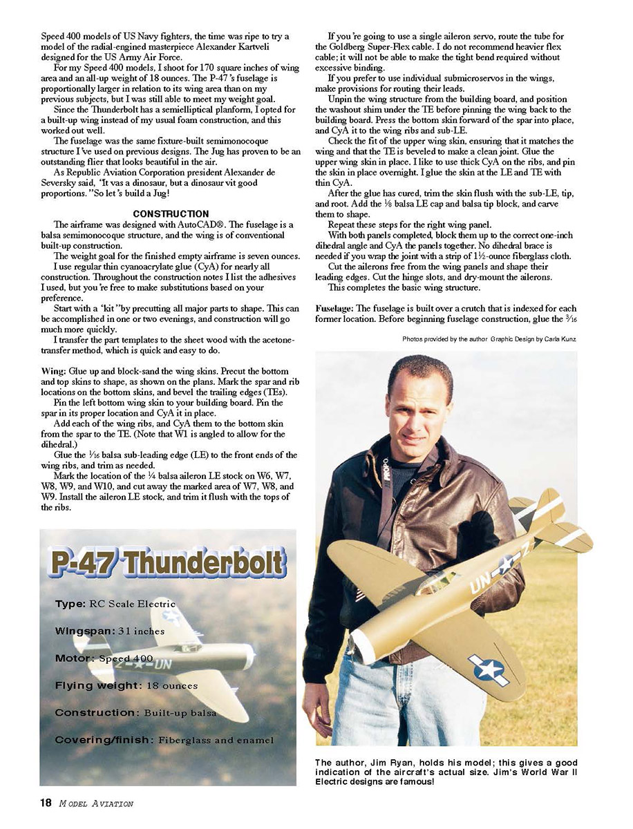
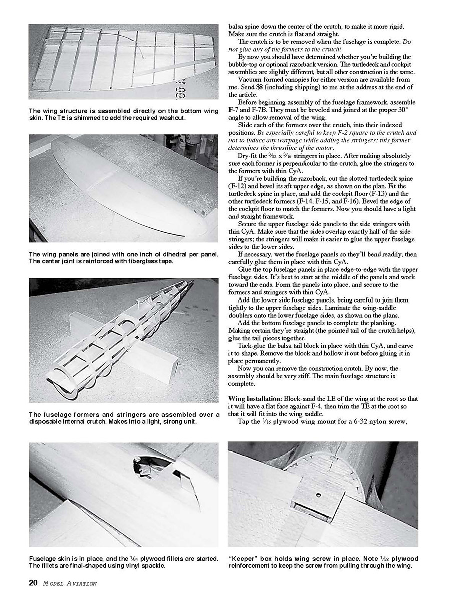
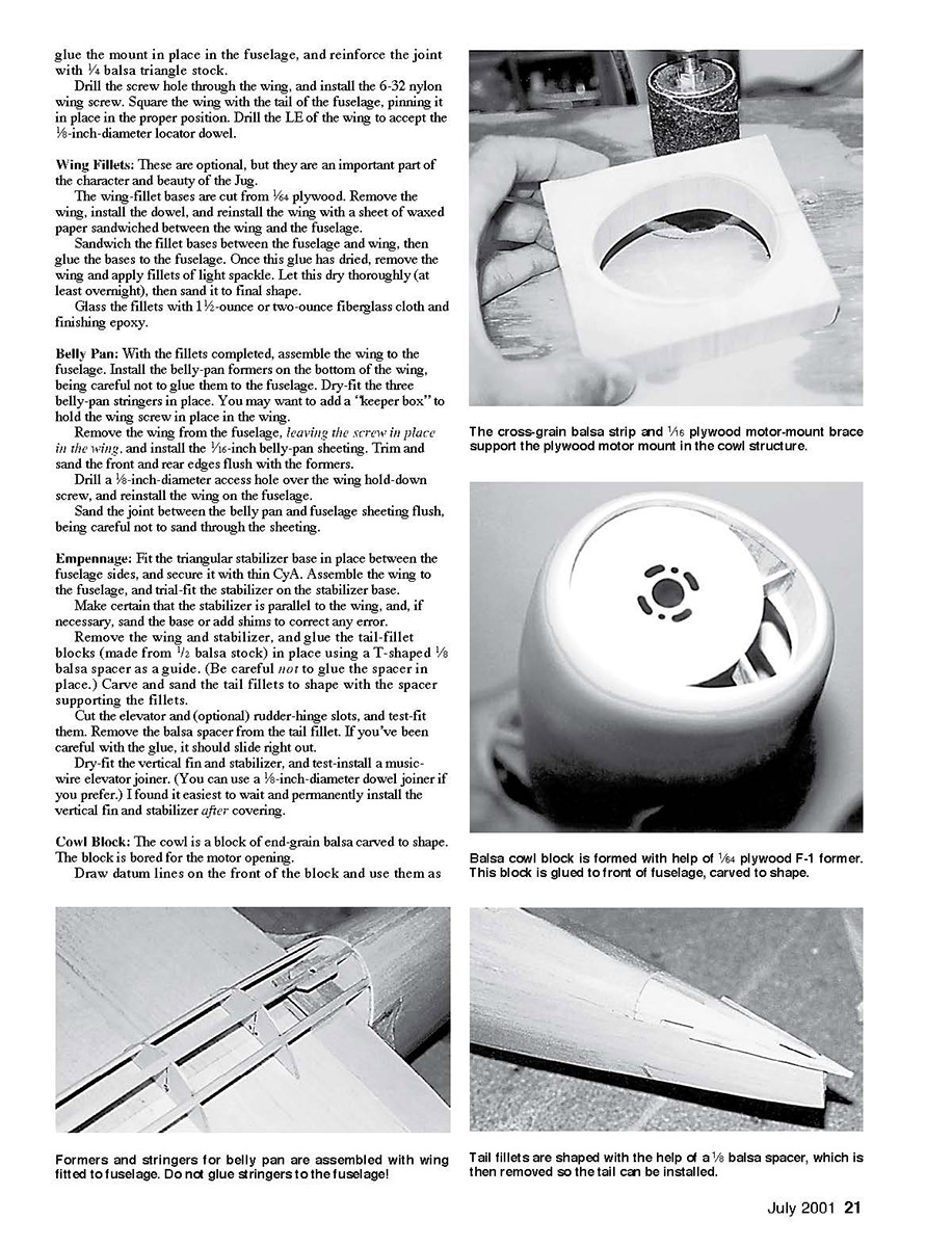
P-47 Thunderbolt
by Jim Ryan
THE P-47 Thunderbolt was one of the immortal fighters of World War II. With its 2,000-horsepower Pratt & Whitney R-2800 radial engine, its heavy armor protection, and its awesome armament of eight .50-caliber machine guns, the "Jug" (for Juggernaut) was the antithesis of lightweight British and German fighters, such as the Spitfire and the Bf 109.
When first deployed as an escort fighter in the 8th Air Force, the P-47 suffered at the hands of lighter German opponents flown by veteran pilots.
However, as P-47 pilots gained experience with their powerful mounts, and as fighter leaders—such as the great "Hub" Zemke—formulated better doctrine and tactics, the balance swung inexorably to the Allied side.
The P-47 eventually amassed an impressive record as an escort fighter. And as P-47 groups shifted to a ground-attack and close air-support role, the Jug gained a reputation as a fearsome gunnery platform whose tough construction brought its pilots home mission after mission.
Having designed a series of successful Speed 400 models of US Navy fighters, the time was ripe to try a model of the radial-engined masterpiece Alexander Kartveli designed for the US Army Air Force.
For my Speed 400 models, I shoot for 170 square inches of wing area and an all-up weight of 18 ounces. The P-47’s fuselage is proportionally larger in relation to its wing area than on my previous subjects, but I was still able to meet my weight goal.
Since the Thunderbolt has a semicelular platform, I opted for a built-up wing instead of my usual foam construction, and this worked out well.
The fuselage was the same fixture-built semimonocoque structure I’ve used on previous designs. The Jug has proven to be an outstanding flier that looks beautiful in the air.
As Republic Aviation Corporation president Alexander de Seversky said, “It was a dinosaur, but a dinosaur with good proportions.” So let’s build a Jug!
CONSTRUCTION
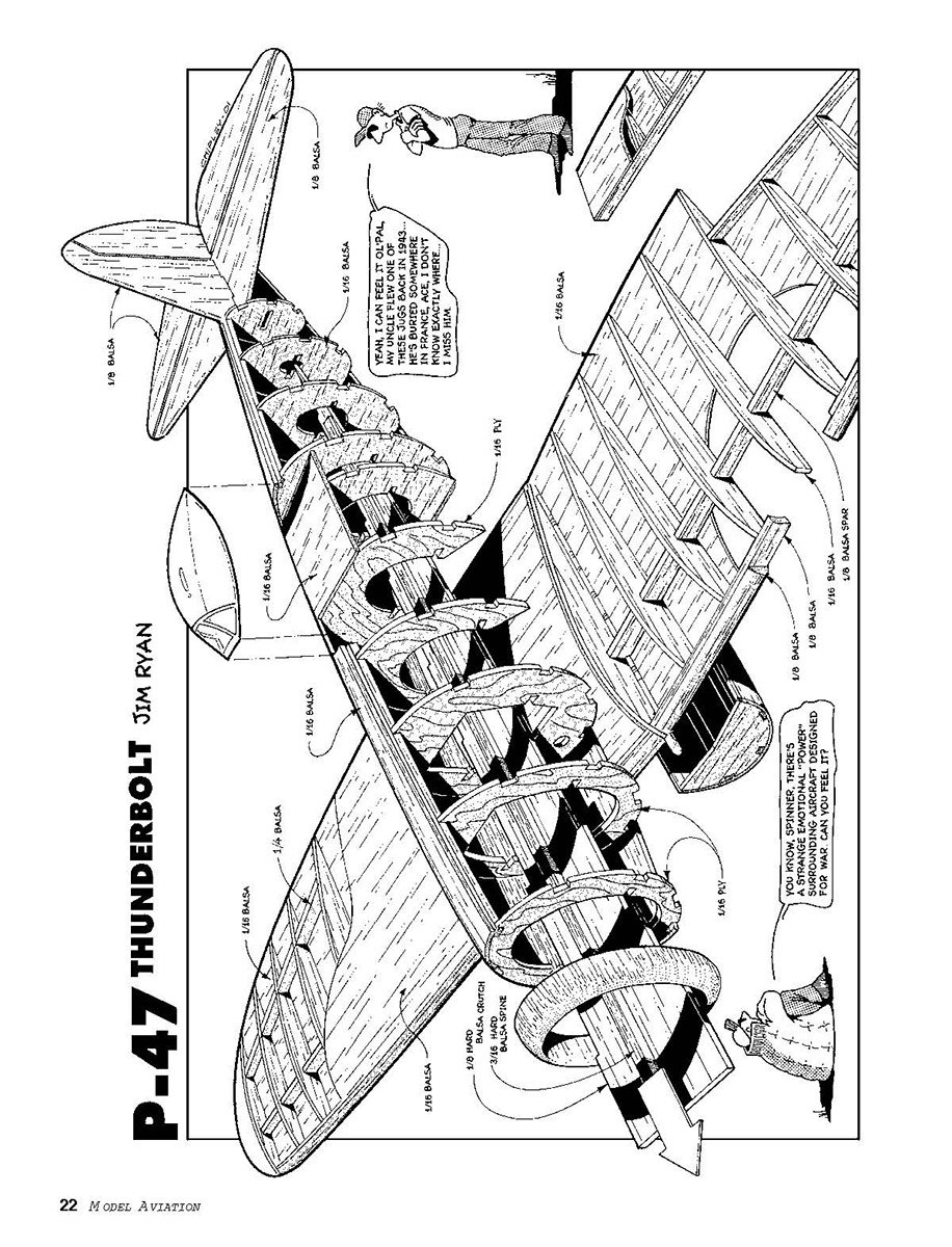
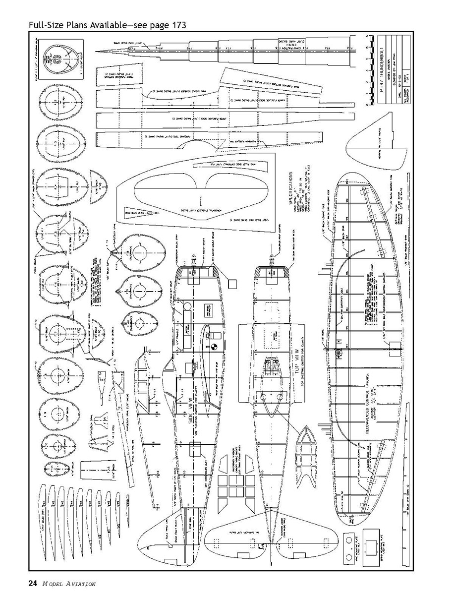
The airframe was designed with AutoCAD®. The fuselage is a balsa semimonocoque structure, and the wing is of conventional built-up construction.
The weight goal for the finished empty airframe is seven ounces. I use regular thin cyanoacrylate glue (CyA) for nearly all construction. Throughout the construction notes I list the adhesives I used, but you’re free to make substitutions based on your preference.
Start with a “kit” by precutting all major parts to shape. This can be accomplished in one or two evenings, and construction will go much more quickly.
I transfer the part templates to the sheet wood with the acetone-transfer method, which is quick and easy to do.
Wing
- Glue up and block-sand the wing skins. Precut the bottom and top skins to shape, as shown on the plans. Mark the spar and rib locations on the bottom skins, and bevel the trailing edges (TEs).
- Pin the left bottom wing skin to your building board. Pin the spar in its proper location and CyA it in place.
- Add each of the wing ribs, and CyA them to the bottom skin from the spar to the TE. (Note that W1 is angled to allow for the dihedral.)
- Glue the 1/16 balsa sub-leading edge (LE) to the front ends of the wing ribs, and trim as needed.
- Mark the location of the 1/8 balsa aileron LE stock on W6, W7, W8, W9, and W10, and cut away the marked area of W7, W8, and W9. Install the aileron LE stock, and trim it flush with the tops of the ribs.
- If you’re going to use a single aileron servo, route the tube for the Goldberg Super-Flex cable. I do not recommend heavier flex cable; it will not be able to make the tight bend required without excessive binding.
- If you prefer to use individual submicroservos in the wings, make provisions for routing their leads.
- Unpin the wing structure from the building board, and position the washout shim under the TE before pinning the wing back to the building board. Press the bottom skin forward of the spar into place, and CyA it to the wing ribs and sub-LE.
- Check the fit of the upper wing skin, ensuring that it matches the wing and that the TE is beveled to make a clean joint. Glue the upper wing skin in place. I like to use thick CyA on the ribs, and pin the skin in place overnight. I glue the skin at the LE and TE with thin CyA.
- After the glue has cured, trim the skin flush with the sub-LE, tip, and root. Add the 1/8 balsa LE cap and balsa tip block, and carve them to shape.
- Repeat these steps for the right wing panel.
- With both panels completed, block them up to the correct one-inch dihedral angle and CyA the panels together. No dihedral brace is needed if you wrap the joint with a strip of 1½-ounce fiberglass cloth.
- Cut the ailerons free from the wing panels and shape their leading edges. Cut the hinge slots, and dry-mount the ailerons.
This completes the basic wing structure.
Fuselage
The fuselage is built over a crutch that is indexed for each former location. Before beginning fuselage construction, glue the 3/16 balsa spine down the center of the crutch, to make it more rigid. Make sure the crutch is flat and straight.
The crutch is to be removed when the fuselage is complete. Do not glue any of the formers to the crutch!
By now you should have determined whether you're building the bubble-top or optional razorback version. The turtledeck and cockpit assemblies are slightly different, but all other construction is the same.
Vacuum-formed canopies for either version are available from me. Send $8 (including shipping) to me at the address at the end of the article.
Before beginning assembly of the fuselage framework, assemble F-7 and F-7B. They must be beveled and joined at the proper 30° angle to allow removal of the wing.
Slide each of the formers over the crutch, into their indexed positions. Be especially careful to keep F-2 square to the crutch and not to induce any warpage while adding the stringers; this former determines the thrustline of the motor.
Dry-fit the 3/32 x 3/16 stringers in place. After making absolutely sure each former is perpendicular to the crutch, glue the stringers to the formers with thin CyA.
If you're building the razorback, cut the slotted turtledeck spine (F-12) and bevel its aft upper edge, as shown on the plan. Fit the turtledeck spine in place, and add the cockpit floor (F-13) and the other turtledeck formers (F-14, F-15, and F-16). Bevel the edge of the cockpit floor to match the formers. Now you should have a light and straight framework.
Secure the upper fuselage side panels to the side stringers with thin CyA. Make sure that the sides overlap exactly half of the side stringers; the stringers will make it easier to glue the upper fuselage sides to the lower sides.
If necessary, wet the fuselage panels so they'll bend readily, then carefully glue them in place with thin CyA.
Glue the top fuselage panels in place edge-to-edge with the upper fuselage sides. It's best to start at the middle of the panels and work toward the ends. Form the panels into place, and secure to the formers and stringers with thin CyA.
Add the lower side fuselage panels, being careful to join them tightly to the upper fuselage sides. Laminate the wing-saddle doublers onto the lower fuselage sides, as shown on the plans.
Add the bottom fuselage panels to complete the planking. Making certain they're straight (the pointed tail of the crutch helps), glue the tail pieces together.
Tack-glue the balsa tail block in place with thin CyA, and carve it to shape. Remove the block and hollow it out before gluing it in place permanently.
Now you can remove the construction crutch. By now, the assembly should be very stiff. The main fuselage structure is complete.
Wing Installation
- Block-sand the LE of the wing at the root so that it will have a flat face against F-4, then trim the TE at the root so that it will fit into the wing saddle.
- Tap the 1/16 plywood wing mount for a 6-32 nylon screw. Glue the mount in place in the fuselage, and reinforce the joint with 1/4 balsa triangle stock.
- Drill the screw hole through the wing, and install the 6-32 nylon wing screw. Square the wing with the tail of the fuselage, pinning it in place in the proper position. Drill the LE of the wing to accept the 1/8-inch-diameter locator dowel.
Wing Fillets
These are optional, but they are an important part of the character and beauty of the Jug.
- The wing-fillet bases are cut from 1/16 plywood. Remove the wing, install the dowel, and reinstall the wing with a sheet of waxed paper sandwiched between the wing and the fuselage.
- Sandwich the fillet bases between the fuselage and wing, then glue the bases to the fuselage. Once this glue has dried, remove the wing and apply fillets of light spackle. Let this dry thoroughly (at least overnight), then sand it to final shape.
- Glass the fillets with 1½-ounce or two-ounce fiberglass cloth and finishing epoxy.
Belly Pan
- With the fillets completed, assemble the wing to the fuselage. Install the belly-pan formers on the bottom of the wing, being careful not to glue them to the fuselage. Dry-fit the three belly-pan stringers in place. You may want to add a "keeper box" to hold the wing screw in place in the wing.
- Remove the wing from the fuselage, leaving the screw in place in the wing, and install the 1/16-inch belly-pan sheeting. Trim and sand the front and rear edges flush with the formers.
- Drill a 1/8-inch-diameter access hole over the wing hold-down screw, and reinstall the wing on the fuselage.
- Sand the joint between the belly pan and fuselage sheeting flush, being careful not to sand through the sheeting.
Empennage
- Fit the triangular stabilizer base in place between the fuselage sides, and secure it with thin CyA. Assemble the wing to the fuselage, and trial-fit the stabilizer on the stabilizer base.
- Make certain that the stabilizer is parallel to the wing, and, if necessary, sand the base or add shims to correct any error.
- Remove the wing and stabilizer, and glue the tail-fillet blocks (made from 1/2 balsa stock) in place using a T-shaped 1/8 balsa spacer as a guide. (Be careful not to glue the spacer in place.) Carve and sand the tail fillets to shape with the spacer supporting the fillets.
- Cut the elevator and (optional) rudder-hinge slots, and test-fit them. Remove the balsa spacer from the tail fillet. If you've been careful with the glue, it should slide right out.
- Dry-fit the vertical fin and stabilizer, and test-install a music-wire elevator joiner. (You can use a 1/8-inch-diameter dowel joiner if you prefer.) I found it easiest to wait and permanently install the vertical fin and stabilizer after covering.
Cowl Block
The cowl is a block of end-grain balsa carved to shape. The block is bored for the motor opening.
- Draw datum lines on the front of the block and use them as a guide for installing F-1, which is really just a sanding guide. Glue the block in place onto F-2, and carve and sand to final shape.
- I recommend waiting until the model is covered to install the 1/8 plywood motor mount with thin CyA.
Final Details
- Install the servo mounts with thin CyA. I elected to add a rudder servo for full four-channel control, but it isn't necessary.
- Cut the battery-mounting plate from 1/8 balsa and install it on F-3, F-4, and F-5 using 1/4 triangular stock to reinforce the joints.
- Apply a strip of Velcro to the mounting plate, so that the Ni-Cd pack can be secured. I use .038 music wire for the pushrods, to keep weight to a minimum. On a model this small I prefer to make my control horns from 1/32 plywood, mortised into the surfaces for added strength.
Finishing
Although the P-47 is suitable for film covering, I like to finish my models with fiberglass and paint. Tissue and dope also works well.
I covered the prototype with .56-ounce fiberglass cloth and painted it with enamel paints. It's a replica of the P-47D-15RE that 56th Fighter Group commanding officer Colonel "Hub" Zemke flew in the early months of 1944.
The canopy framing can be painted easily using the frisket masks shown on the plans. Make sure you protect the inside surface of the canopy with masking tape; overspray gets on the inside. After painting the framing, remove the masks and glue the canopy in place with RC-56 or equivalent canopy glue.
Install the hardware, and you're ready to go fly.
Flight Testing
Be careful checking the center of gravity (CG). Start with the CG two inches behind the LE of the wing where it exits the fuselage, and adjust it to suit your tastes.
If you keep the weight near 18 ounces, the Jug should fly just fine.
Takeoff and Landing
- Get a capable assistant to hand-launch the model on the first flights. The airplane needs to be thrown straight and level. If the launcher lobs it upward, it's likely to stall.
- Hold the wings level, and let the model climb as the speed builds.
- Landings are made with a straight-in approach, and the model is held just off the ground until it settles in.
With the washout in the wing, the Jug has very forgiving stall characteristics.
Flight Characteristics
I've been very pleased with the performance and handling of this model. I use eight cells to improve the vertical, but I spend most of each flight at 1/2 to 3/4 throttle.
The Jug will do huge loops and Cuban 8s, and the roll rate is surprisingly fast. Inverted flight is solid. With the active rudder control, Stall Turns, Hammerheads, and Spins are added to your repertoire.
I hope you enjoy your Jug as much as I've enjoyed mine.
Transcribed from original scans by AI. Minor OCR errors may remain.

