
P-61 Black Widow
By Frank B. Baker
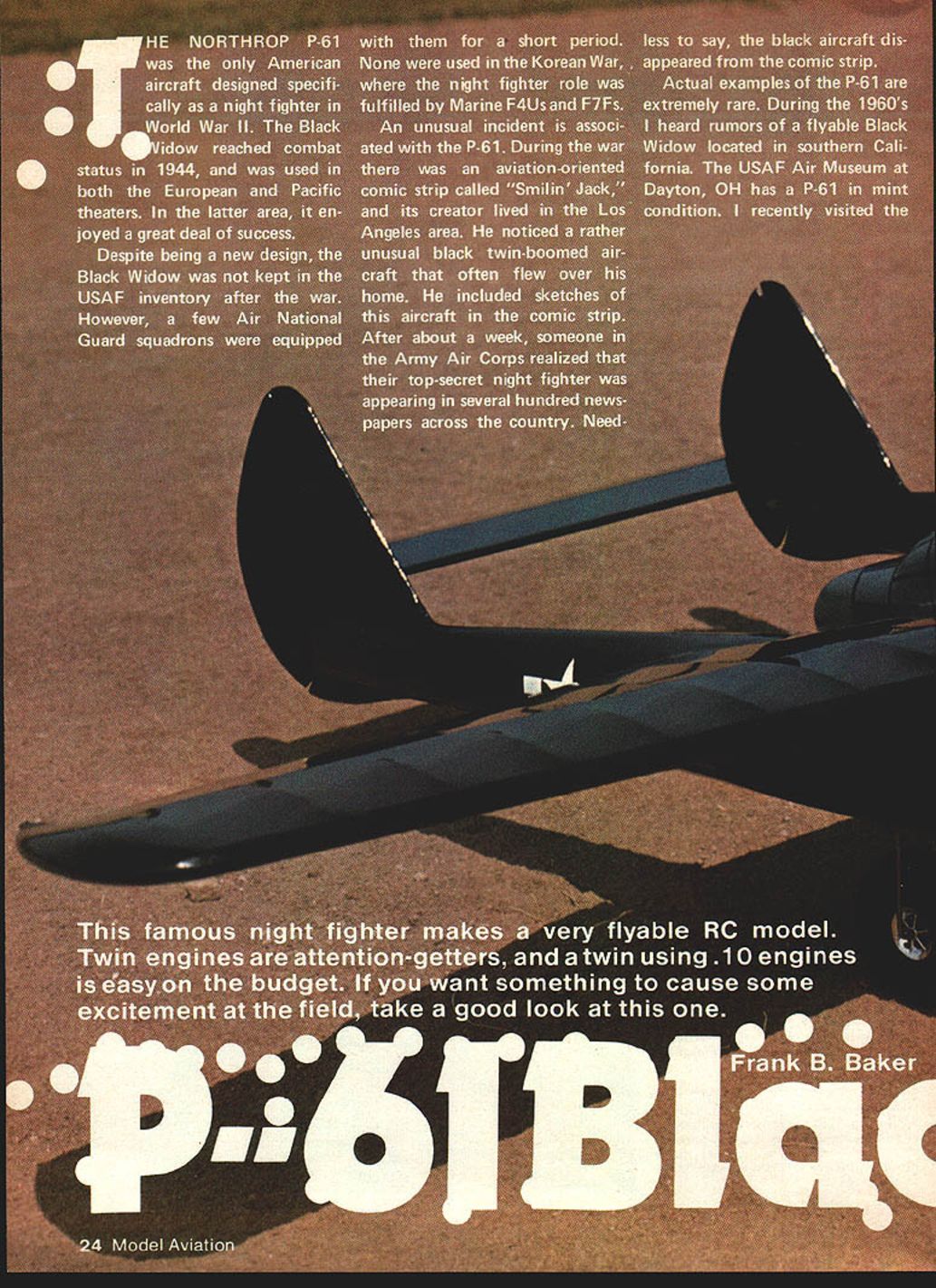
The Northrop P-61 was the only American aircraft designed specifically as a night fighter in World War II. The Black Widow reached combat status in 1944 and was used in both the European and Pacific theaters. In the Pacific it enjoyed a great deal of success.
Despite being a new design, the Black Widow was not retained in the postwar USAF inventory. A few Air National Guard squadrons were equipped with them for a short period. None were used in the Korean War, where the night fighter role was fulfilled by Marine F4Us and F7Fs.
An unusual incident is associated with the P-61. During the war there was an aviation-oriented comic strip called "Smilin' Jack," and its creator lived in the Los Angeles area. He noticed a rather unusual black, twin-boomed aircraft that often flew over his home and included sketches of it in the strip. After about a week someone in the Army Air Forces realized that their top-secret night fighter was appearing in several hundred newspapers across the country. Needless to say, the black aircraft disappeared from the comic strip.
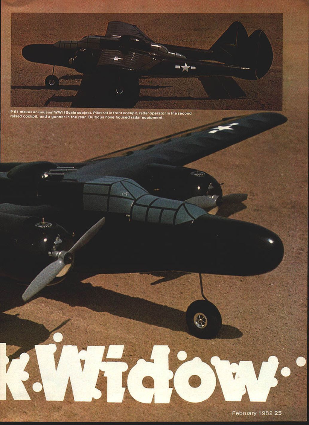
Actual examples of the P-61 are extremely rare. The USAF Museum at Dayton, Ohio has a P-61 in mint condition. I recently visited the museum and was surprised at how small the P-61 seemed. It was parked next to a Douglas B-26, which seemed to be a much larger airplane. The P-61 fuselage is only slightly wider than the pilot's shoulders. The tail booms and rudders were also much smaller than I had anticipated; my perception had been based entirely on photographs.
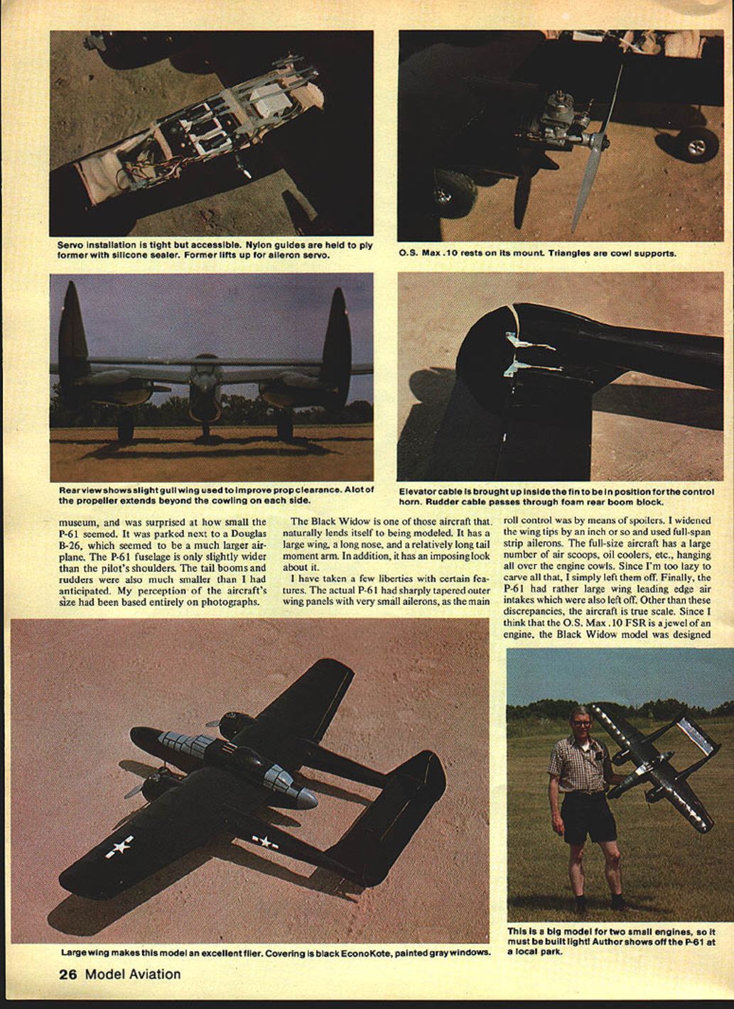
The Black Widow naturally lends itself to modeling. It has a large wing, a long nose, and a relatively long tail moment arm, giving it an imposing look. I took a few liberties with certain features to simplify construction and improve flying characteristics:
- The full-size P-61 had sharply tapered outer wing panels with very small ailerons; the main roll control was by spoilers. I widened the wing tips slightly and used full-span strip ailerons.
- The full-size aircraft has many air scoops, oil coolers, and leading-edge intakes; I left most of these off for simplicity.
- The model was designed around the O.S. Max .10 FSR engine.
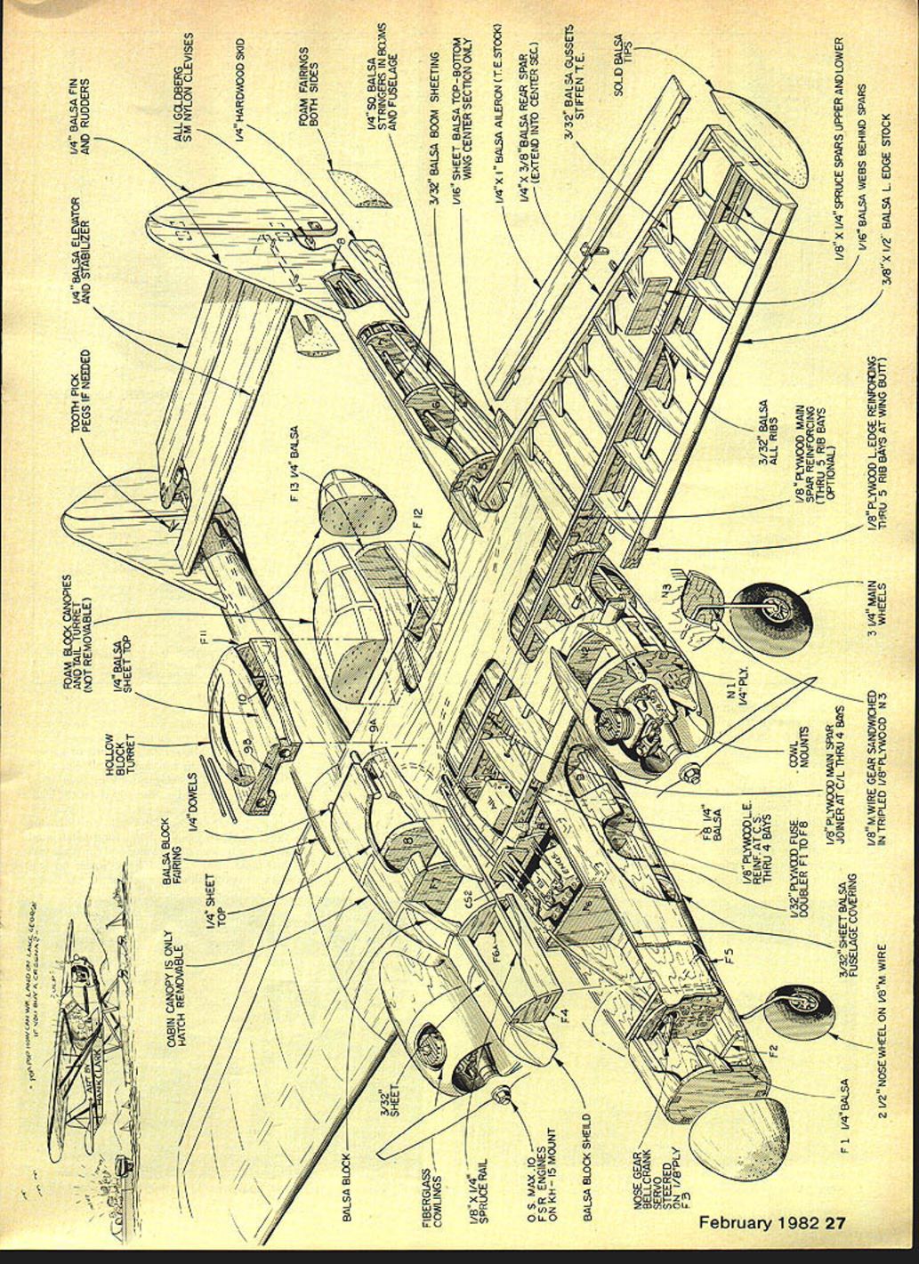
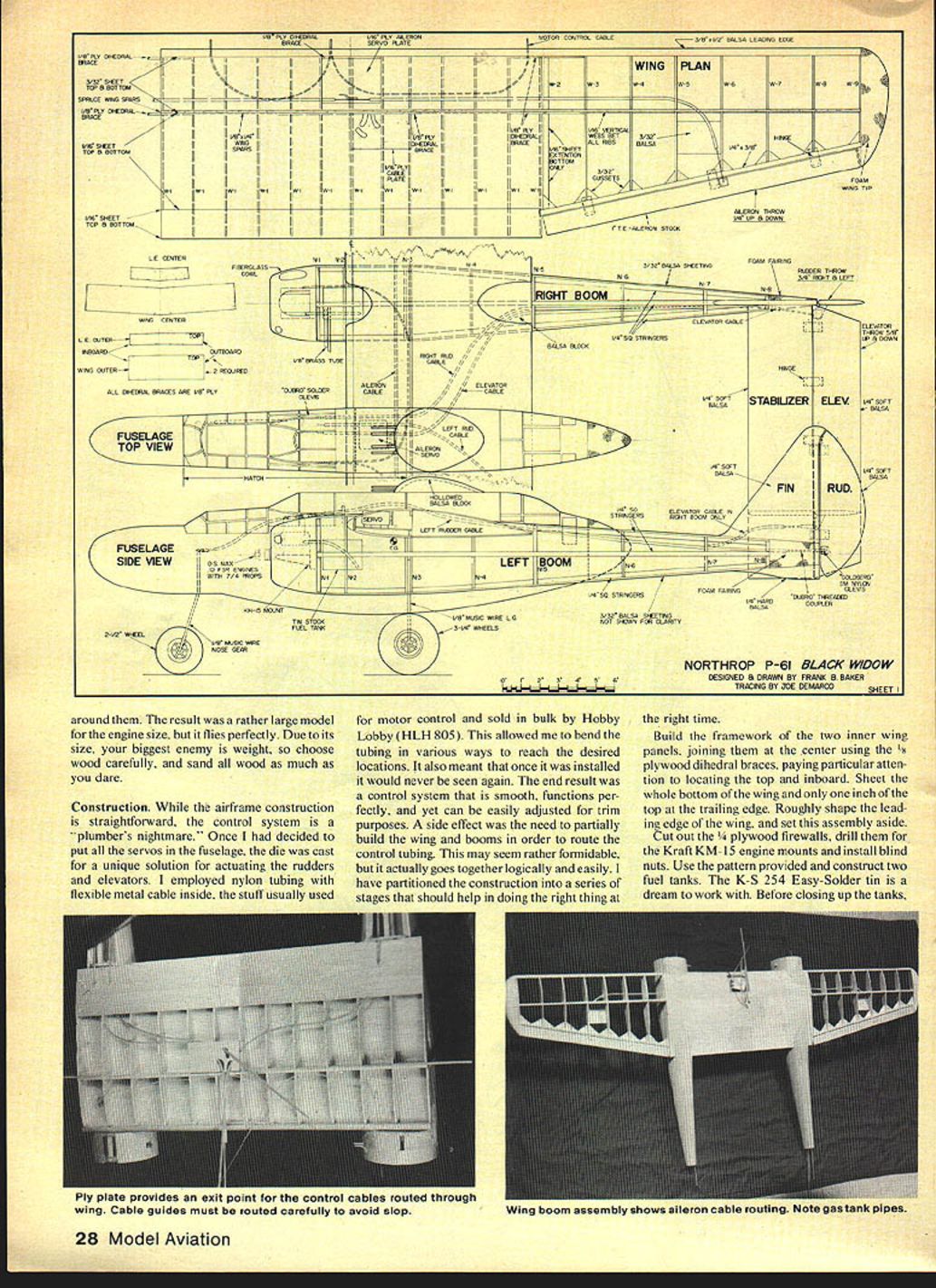
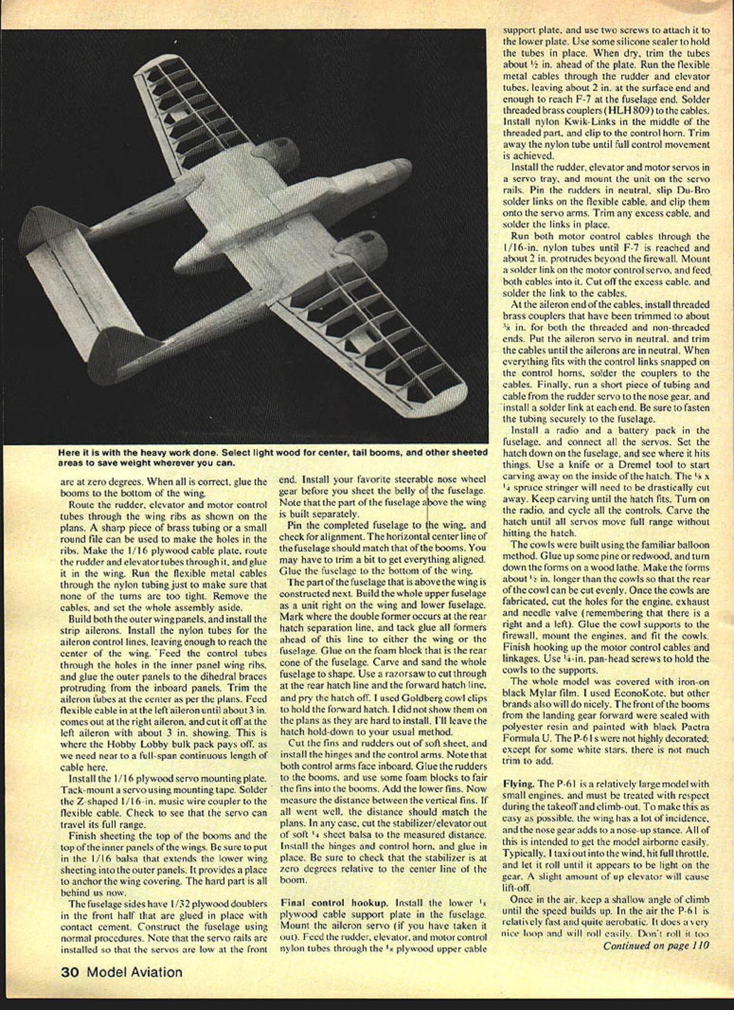
Due to its size, weight is the model's biggest enemy. Choose wood carefully and sand as much as you dare. Construction of the airframe is straightforward; the control system is more complex. Once I decided to put all servos in the fuselage I devised a unique solution for actuating the rudders and elevators: nylon tubing with flexible metal cable inside (motor-control cable sold in bulk, Hobby Lobby HLH-805). The tubing can be bent to reach desired locations and is hidden once installed. The result is a smooth control system that functions perfectly and is easily adjusted for trim. A side effect is the need to partially build the booms to route the control tubing, which may seem daunting but goes together logically.
Materials and Parts (high-level)
- Cabin canopy: balsa, hatch removable
- Fairing: 1/4" balsa block
- Fiberglass cowlings
- 3/32" sheet top
- 1/8" x 1/4" spruce rail
- Foam block canopies and tail turret: removable hollow block
- 1/4" balsa turret sheet top
- Goldberg small nylon clevises
- Toothpick (for small linkages)
- 1/4" balsa elevator
- 1/4" balsa fin, stabilizer, and rudders (1/4" hardwood side, tabs if needed)
- Foam fairings
- 1/4" balsa stringers in booms and fuselage
- 3/32" balsa boom sheeting
- 1/16" sheet balsa top and bottom wing center section only
- 1/4" balsa aileron stock (1/4" x 3/8")
- Rear spar — extend into center section
- 3/32" balsa gussets to stiffen
- 1/32" plywood fuselage cowl doubler for mounts
- 1/8" plywood main spar
- 1/4" balsa and 3/32" sheet balsa joiner at centerline through fuselage
- Covering: iron-on black Mylar film (EconoKote used)
- Landing gear: 1/8" wire gear, sandwiched in 3/32" plywood main, tripled 1/8" plywood
- 3" wheels; 2-1/2" nose wheel on 3/32" wire
- 1/8" plywood main spar reinforcing through 5 rib bays (optional)
- 1/8" plywood ledge reinforcing through 5 rib bays at wing butt
- Solid balsa tips
- 7/16" balsa webs behind spars
- 3/8" x 1/2" balsa leading edge stock
- 1/8" x 1/4" spruce spars upper and lower
- 1 servo plate; motor control cable
- 3/8" lite balsa leading edge cage brace
- 1/16" sheet for bottom of center section
- All internal braces as per plans
- Hinges for all ailerons and control surfaces
- Right boom: gear, raw axle, grass tire on 1/8" sheet; stabilizer and elevator sheet as shown on drawing
- Soldered brass couplers (HLH 809) and nylon Kwik-Links
- Du-Bro solder links, Goldberg cowl clips (optional)
Construction
Overall approach: partition the build into stages so tasks are done in the right order. Below are the key construction steps and tips.
Wing and center section
- Build the framework of the two inner wing panels and join them at the center using the 1/16" plywood dihedral braces. Pay attention to locating the top and inboard edges.
- Sheet the entire bottom of the wing and only about one inch of the top at the trailing edge. Roughly shape the leading edge and set the assembly aside.
- Build the outer wing panels later and install full-span strip ailerons (I widened the tips slightly and used full-span ailerons instead of small full-size aileron areas).
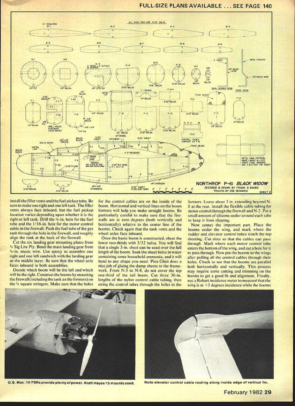
Firewalls and fuel tanks
- Cut the 1/8" plywood firewalls, drill them for the Kraft KM-15 engine mounts, and install blind nuts.
- Use the pattern provided to construct two fuel tanks. K-S 254 Easy-Solder tin works well. Install filler vents and the fuel pickup tube before closing the tanks. Make one right and one left tank — filler vents always face inboard; pickup locations differ.
- Drill a 5/8" hole for the fuel tube and a 1/16" hole for the motor control cable in the firewall. Push the fuel tube through and roughly align the tank behind the firewall.
Landing gear
- Cut six landing gear mounting plates from 1/8" Sig Lite Ply.
- Bend the main landing gear from 1/8" music wire.
- Epoxy a right and left sandwich with the landing gear as the middle layer. Ensure the wheel axle faces inboard in both assemblies.
Booms and preliminary assembly
- Decide which boom is left and right. Construct each boom by mounting the firewall (with tank and formers) on 1/4" square stringers. Make sure the control cable holes are on the inside of the boom, and use horizontal and vertical lines on formers to ensure straightness.
- Ensure firewalls are at zero degrees both vertically and horizontally relative to the boom centerline. Check that tank vents and wheel axles face inboard.
- Sheet the lower two-thirds of the boom with 3/32" balsa. A single 3" sheet can cover the full length. Soak sheet balsa in water with a little household ammonia to bend; use Pica Glut to glue damp sheets.
- From former N-5 to N-8, do not cover the top one-third of the tail boom (allows routing and access).
- Cut three 36" lengths of nylon control-cable tubing and string them through the boom formers, leaving about 3" beyond N-8 at the rear. Install flexible motor-control cable tubing through the firewall and N-2; seal with silicone.
Fitting booms to the wing and alignment
- Place the booms under the wing and mark where rudder and elevator control tubes touch the top sheeting; cut slots for the cables to pass through.
- Mark where motor-control tubes enter the bottom of the wing and cut holes for them.
- Pin the booms to the wing after routing all control cables. Check that the booms are parallel horizontally and vertically. Trim booms as needed for a good fit.
- Use a Robart incidence meter to ensure the wing is at +3° incidence while the booms are at 0°. When correct, glue the booms to the bottom of the wing.
Control tube routing and cable plates
- Route rudder, elevator, and motor-control tubes through the wing ribs as shown on the plans. Use a sharp brass tube or a small round file to make holes.
- Make the 1/16" plywood cable plate, route the rudder and elevator tubes through it, and glue it in the wing.
- Run flexible metal cables through the nylon tubing to check turns. Remove cables and set assembly aside.
Outer wing panels and aileron system
- Build both outer wing panels and install strip ailerons.
- Install nylon tubes for aileron control lines, leaving enough to reach the wing center.
- Feed tubes through holes in the inner panel ribs and glue the outer panels to the dihedral braces.
- Trim aileron tubes at the center as per plans. Feed flexible cable from left aileron through to the right aileron so you have one near-continuous length; this is where bulk-pack cable (HLH-805) pays off.
- Install the 1/16" plywood servo mounting plate in the wing. Tack-mount a servo to check travel.
- Solder a Z-shaped 1/16" music wire coupler to the flexible cable and verify full servo travel.
Finish sheeting
- Finish sheeting the top of the booms and the top of the inner wing panels. Install the 1/16" balsa extension that continues lower wing sheeting into the outer panels to anchor the covering.
Fuselage
- Glue 1/32" plywood doublers to the fuselage sides in the front half with contact cement.
- Construct the fuselage using normal procedures; note servo rails are installed so servos are low at the front end.
- Install steerable nose wheel gear before sheeting the fuselage belly.
- The portion of the fuselage above the wing is built separately. Pin the completed fuselage to the wing and check alignment — the fuselage centerline should match the booms. Trim and glue when aligned.
- Build the upper fuselage on the wing and lower fuselage. Mark the double former at the rear hatch separation line and tack-glue all formers ahead of this line to the wing or fuselage.
- Glue on the foam block rear cone, carve and sand to shape. Use a razor saw to cut the rear and forward hatch lines and remove hatches. Goldberg cowl clips can be used to hold the forward hatch (optional).
Tail surfaces
- Cut fins and rudders from soft sheet balsa, install hinges and control arms; both control arms face inboard.
- Glue rudders to booms and use foam blocks to fair fins into booms. Add lower fins.
- Measure the distance between vertical fins and cut stabilizer/elevator from 1/8" soft balsa to match. Install hinges and control horn, and glue in place. Check stabilizer is at 0° relative to the boom centerline.
Final control hookup
- Install the lower 1/8" plywood cable support plate in the fuselage.
- Mount the aileron servo if removed. Feed rudder, elevator, and motor-control nylon tubes through the 3/32" plywood upper cable support plate and attach with two screws to the lower plate. Use silicone to hold tubes, then trim tubes about 1/8" ahead of the plate.
- Run flexible metal cables through rudder and elevator tubing, leaving about 2" at the surface end and enough to reach F-7 at the fuselage end. Solder threaded brass couplers to the cables, install nylon Kwik-Links, and clip to control horns. Trim nylon tubing until full control movement is achieved.
- Install rudder, elevator, and motor servos in a servo tray and mount on servo rails. Pin rudders neutral, slip Du-Bro solder links on the flexible cable, and clip to the servo arms. Trim excess cable and solder links.
- Run motor-control cables through 1/16" nylon tubes until F-7 with about 2" protruding beyond the firewall. Mount a solder link on the motor-control servo, feed both cables into it, trim excess, and solder.
- At the aileron ends, install threaded brass couplers trimmed to ~3/8" for both threaded and non-threaded ends. Neutralize aileron servo and trim cables until ailerons are neutral. When links snap on and fit, solder couplers to the cables.
- Run a short piece of tubing and cable from the rudder servo to the nose gear and install solder links at each end. Fasten tubing securely to the fuselage.
Radio, battery, and hatch fitting
- Install radio and battery pack in the fuselage and connect servos.
- Set the hatch in place and check for interference. Carve the inside of the hatch (spruce stringer will need trimming) until all servos move full range without hitting the hatch.
Cowls and final engine installation
- Cowls were built using the balloon method. Glue pine or redwood up and turn forms on a wood lathe. Make forms about 1/2" longer than the cowls so the rear of the cowl can be cut even.
- Cut holes for engine, exhaust, and needle valve (remember right and left).
- Glue cowl supports to the firewall, mount engines, and fit cowls. Finish motor-control cable hook-ups and linkages.
- Use 4-40 pan-head screws to hold cowls to supports.
Covering and finish
- Cover the model with iron-on black Mylar film (EconoKote recommended).
- Seal the front of the booms from the landing gear forward with polyester resin and paint with black Pactra Formula U.
- P-61s were not highly decorated beyond national insignia; trim is minimal.
Flying
The P-61 model is relatively large with small engines and must be treated with respect during takeoff and climb-out. To assist, the wing has generous incidence and the nose gear gives a nose-up stance to get the model airborne easily.
- Taxi into the wind, apply full throttle, and let it roll until it appears light on the gear. A slight up elevator will lift it off.
- Keep a shallow climb until speed builds. In the air the P-61 is relatively fast and quite aerobatic — it loops nicely and rolls easily. Do not roll too slowly, as fixed fuel pickups can starve an engine in a slow roll.
- The Black Widow excels at touch-and-goes. Use a wide pattern and set up a long final approach. Even at low throttle it tends not to lose altitude and assumes a flat attitude on final that can be held to the ground; full throttle returns it to the air immediately.
- With large wheels, grass-field landings have been smooth greasers with no bounce. Single-engine performance is excellent and gives time to set up a landing. Ailerons and rudders are adequate for single-engine control.
Handling summary: despite its size and small engines, the P-61 handles like a trainer. It is docile, has no hidden vices, goes where you point it, and provides a great deal of realism.
Transcribed from original scans by AI. Minor OCR errors may remain.

