
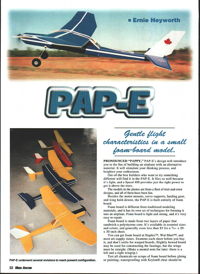
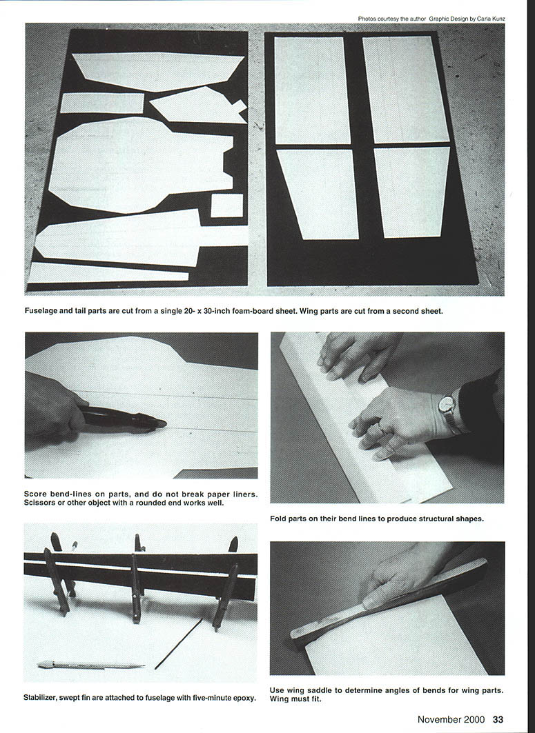
PAP-E
Gentle flight characteristics in a small foam-board model.
PRONOUNCED "PAPPY," PAP-E's design will introduce you to the fun of building an airplane with an alternative material. It will stimulate your thinking process, and heighten your enthusiasm.
Out-of-the-box builders who want to try something different will find it in the PAP-E. It flies so well because it's light, and a Speed 400 provides just the right power to get it above the trees.
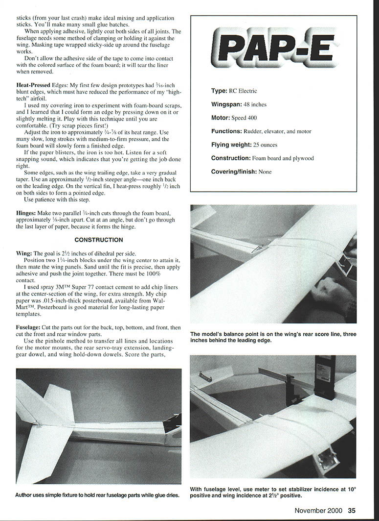
The models in the photos are from a fleet of trial-and-error designs, and all of them have been fun.
Besides the motor mounts, servo supports, landing gear, and wing hold-downs, the PAP-E is built entirely of foam board.
Foam board is different from traditional modeling materials, and it has its own set of techniques for forming it into an airplane. Foam board is light and strong, and it's very easy to repair.
Foam board is made from two layers of paper that sandwich a polystyrene core. It's available in assorted sizes and colors, and generally costs less than $5 for a 3/16- x 20- x 30-inch sheet.
You can get foam board at Staples™, Wal-Mart™, and most art-supply stores. Examine each sheet before you buy it, and don't settle for warped boards. Slightly bowed board may be used for constructing the fuselage, but the wings must be straight. (Make a mental note for later: there is a left and a right wingtip.)
Test all chemicals on scraps of foam board before gluing or painting; waterproofing with Krylon® clear should be — I can't find any continuing article text on this scanned page — it contains photos with captions but no body text that continues the article after "waterproofing with Krylon® clear should be". Please provide the next scanned page (or a higher-resolution image of this page) so I can continue the primary article text from where the prior page left off.
Okay, although the use of clear dope or various adhesives requires your personal testing and approval.
If you're a traditional balsa builder, you'll be in a new environment with foam board.
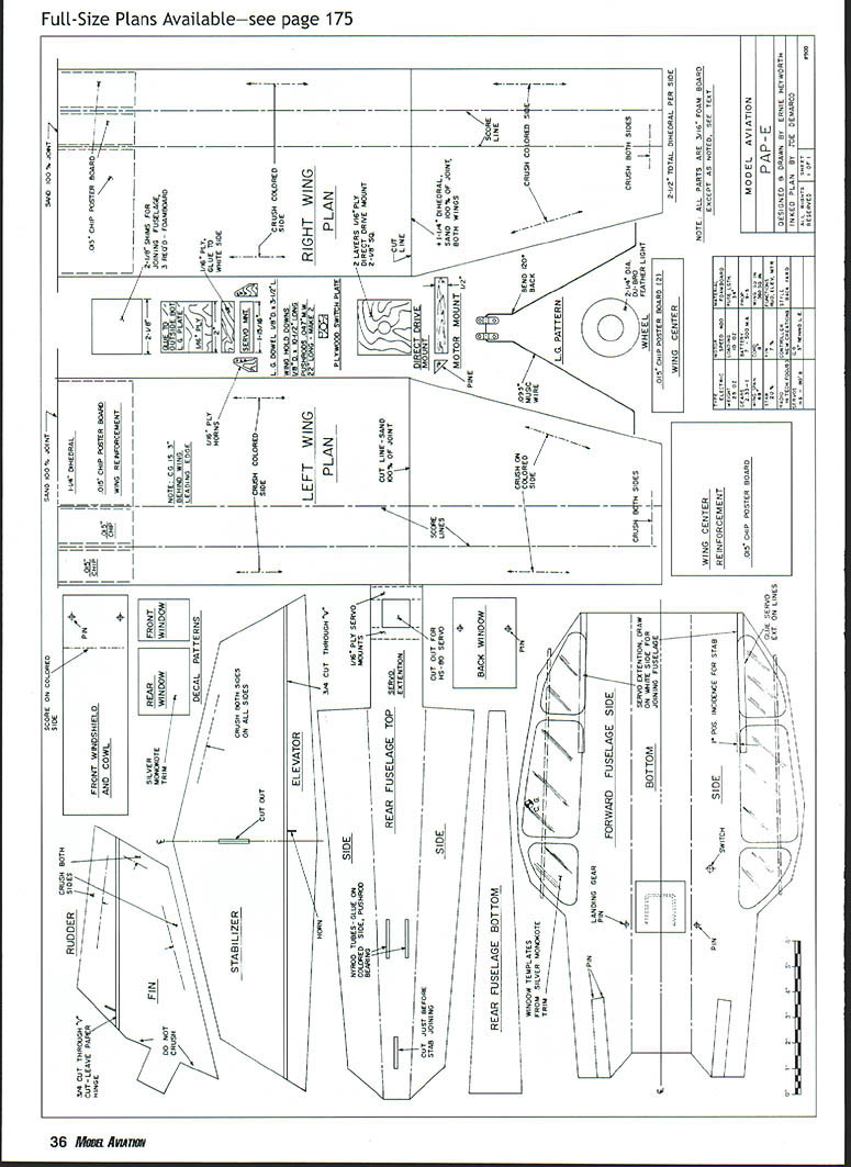
Tracing the Templates
Templates for the parts can easily be cut from the plans.
Before doing so, note how the parts will be laid out over the foam-board sheets. Two 20- x 30-inch sheets should be enough to build the PAP-E.
If you've purchased colored foam board, work on the white side. Cut the templates out and arrange them over the foam board, then trace their outlines onto the sheets. Score lines—where the foam board will be folded to form parts—must also be transferred from the templates.
To transfer these and other important markings, I use the old trick of making pinholes through the templates into the foam board, then removing the templates and drawing lines over the tiny pinhole guides.
Transfer the score lines in this manner, then transfer the locations for the motor mounts, where the two parts of the fuselage join, and the cut-lines for the hinges.
Cutting
A very sharp #11 blade in a hobby knife or a single-edge razor blade is the ideal tool. Work over a smooth surface, and make your cuts against a steel rule, to assure straightness. I cut over old pieces of posterboard.
Hold the knife vertical as you cut, and don't try to cut all the way through in the first pass. Two or three passes will do a neater job.
Scoring
Practice this procedure on a scrap before committing to the parts.
Apply light pressure along the score lines with a rounded object, such as the back of a scissors or a screen-door beader.
Press gently along each line on your first pass, and try not to break the paper liner. Press more firmly on your second pass, then break the scores evenly along the entire length of each line, a little at a time.
The two wing scores will hold the airfoil shape. Score pressure on the wing parts should have developed a bow of approximately 3/4 inch, or enough to match the wing saddle on the fuselage. If it has not, bend the parts over more sharply.
Sanding
Use a large, flat board or aluminum as a plate. Use a commercial tool, or make your own sanding block by gluing 100-grit sandpaper to a board; I use a 1/2- x 3- x 15-inch piece. This step is important. Sand both sides of the curved wing panels, until 100% of the wing/saddle joint touches.
Take the time to get it right; keep refitting until you're satisfied.
Adhesive
I used five-minute epoxy on everything (I'm allergic to cyanoacrylate), which made working with foam board easy and fast.
Mix the five-minute glue and hardener on a Post-It®-type notepad or a plastic coffee-can lid. A 1/8-inch dowel or a few scraps of foam board serve as mixing sticks. Apply a thin fillet of epoxy to the joint between mating parts and clamp or weight the assembly until the epoxy hardens. For small or delicate joints, use 30-minute epoxy or foam-safe CA. Avoid solvents that attack the polystyrene core.
Sticks (from your last crash) make ideal mixing and application sticks. You'll make many small glue batches.
When applying adhesive, lightly coat both sides of all joints. The fuselage needs some method of clamping or holding it against the wing. Masking tape wrapped sticky-side up around the fuselage works.
Don't allow the adhesive side of the tape to come into contact with the colored surface of the foam board; it will tear the liner when removed.
Heat-Pressed Edges
My first few design prototypes had 3/16-inch blunt edges, which must have reduced the performance of my "high-tech" airfoil.
I used my covering iron to experiment with foam-board scraps, and I learned that I could form an edge by pressing down on it or slightly melting it. Play with this technique until you are comfortable. (Try scrap pieces first.)
Adjust the iron to approximately 3/4 of its heat range. Use many slow, long strokes with medium-to-firm pressure, and the foam board will slowly form a finished edge.
If the paper blisters, the iron is too hot. Listen for a soft snapping sound, which indicates that you're getting the job done right.
Some edges, such as the wing trailing edge, take a very gradual taper. Use an approximately 1/2-inch steeper angle—one inch back on the leading edge. On the vertical fin, I heat-press roughly 1/2 inch on both sides to form a pointed edge.
Use patience with this step.
Hinges
Make two parallel 3/8-inch cuts through the foam board, approximately 1/8-inch apart. Cut at an angle, but don't go through the last layer of paper, because it forms the hinge.
CONSTRUCTION
Wing
The goal is 2½ inches of dihedral per side.
Position two 1¼-inch blocks under the wing center to attain it, then mate the wing panels. Sand until the fit is precise, then apply adhesive and push the joint together. There must be 100% contact.
I used spray 3M™ Super 77 contact cement to add chip liners at the center-section of the wing, for extra strength. My chip paper was .015-inch-thick posterboard, available from Wal-Mart™. Posterboard is good material for long-lasting paper templates.
Fuselage
Cut the parts out for the back, top, bottom, and front, then cut the front and rear window parts.
Use the pinhole method to transfer all lines and locations for the motor mounts, the rear servo-tray extension, landing-gear dowel, and wing hold-down dowels. Score the parts, draft them with drafting tape until the epoxy cures. Glue the front and back windows onto the forward-fuselage section. Use 2/8-inch shims as inside spacers.
This step is important! Fit the front and rear fuselage sections together by inserting the rear's servo-extension sections into the back of the front part.
Before applying adhesive, be certain that all the parts interlock correctly and that the servo-tray extension is on your alignment lines. This step doesn't just make the fuselage sections; it also determines the incidence between the stabilizer and the wing.
Add the window decals before installing the wing hold-down dowels, then install the motor mount, if using the direct-drive system, and all dowels. The plywood landing-gear mount is installed on the outside, near the landing gear hold-down dowel. The PAP-E's landing gear wire is bent from .080-inch-diameter wire. Bend it, and check the fit to the fuselage.
Add the preassembled tail section and install the radio.
Empennage
Glue the vertical fin into the horizontal stabilizer.
Use epoxy to glue the assembled tail section into the rear of the fuselage. Keep it aligned while the epoxy cures.
With the rear of the fuselage level, use an incidence meter to verify that the stabilizer is 10° positive and the wing is 2½° positive.
Control System
Fabricate small control horns from 1/16-inch plywood. They must be long enough to sink into a knife slit in the foam board. Drill the horns to accommodate .047-inch music wire before installing them in the control surfaces.
I laminated the foam board with 1/16-inch plywood beneath the servo-mounting areas, to add depth for the servo screws to bite. Install the rudder and elevator servos.
I use .047-inch wire for pushrods, with an adjustable pedestal on the servo arm.
The pushrods travel through the rear window, along the outside top of the fuselage, through a piece of Nyrod, and back into the plywood control horn, where they connect with a Z-bend. The small piece of Nyrod serves as a midway support bearing.
Motor System
My favorite electric motor system is a Speed 400 with a GR 170323 2.33:1 gearbox, a New Creations M-30 speed controller, a seven-cell 500 mA battery, and a 9 x 5 fixed-pitch propeller.
This gearbox has mounting flanges like a wet motor, and is an ideal fit to the PAP-E's motor mounts.
Use Velcro to mount the receiver beneath the servos. The battery should be located as far forward as possible, almost touching the back of the motor.
Center of Gravity and Control Throw
Use #62 rubber bands to hold the wing to the fuselage. The hinge-style landing gear is also secured by a #62 rubber band, which prevents damage in the event of a less-than-perfect landing. Mount the wing and the gear.
The PAP-E should hang slightly nose-down when balanced with your fingers on the wing's rear score line, three inches behind the leading edge.
- Rudder throw: 1/2-inch left and 1/2-inch right of center.
- Elevator travel: 3/8-inch up and 3/8-inch down from center.
Flight
I don't use a wire tail skid on my PAP-E, so takeoffs usually result in a torque-predictable slight left turn. Right motor thrust and a skid would probably tame this, but the model gets airborne quickly, and it doesn't take long for the right rudder to take control.
The airplane is a joy to fly, and is easily kept within the boundaries of any typical flying field. The high-undercarriage wing does not lend itself to inverted flight, but the PAP-E will relax you with its gentle habits, slow flying, and easily controlled turns.
The PAP-E is an ideal first airplane and a perfect fit for people who like to relax and enjoy the fun of quiet flight.
This design has been a fun-filled project for me, and the trial-and-error engineering has maintained my enthusiasm for the ever-changing design.
The first of six airplanes was much smaller, with a conventional stabilizer, straight wings, and direct drive. Then I went through a V-tail period; if I had that to do again, I would add a dorsal fin. With the last few models, I concentrated on lengthening the fuselage and changing the wing in incidence, to make it a better-flying machine.
I hope the model inspires you to investigate and to apply your own changes and improvements. There is room for better techniques when working with this material. Shape, size, color, flying characteristics, and power can be refined.
The PAP-E is a designer's delight. MA
Ernie Heyworth 109 Hidden Ln. Horseheads, NY 14845
Sources:
- ESC (Electronic Speed Control): New Creations R/C, Box 496, Wills, TX 77378, (409) 856-4630
- Foam board: (800) TRY-HUNT, www.hunt-corp.com
PAP-E
Type: RC Electric
Wingspan: 48 inches
Motor: Speed 400
Functions: Rudder, elevator, and motor
Flying weight: 25 ounces
Construction: Foam board and plywood
Covering/finish: None
(Continued on page 43)
Transcribed from original scans by AI. Minor OCR errors may remain.

