
Park View: GWS-15 EDF
Ben Lanterman
IN THE LATE 1960s and early 1970s, the US Air Force needed a fighter capable of operating at a performance level that would allow it to counter the many high-performance designs coming out of the Russian design bureaus. The Air Force had many airplanes flying at the time, but few were of the air-combat variety.
The Navy’s F-4 Phantom was good in the air-combat role, and consequently the Air Force pressed it into service. However, it had no air-to-air gun capability and suffered a performance hit when considered for the Air Force air-superiority role; it carried the extra structural weight needed to land on an aircraft carrier.
Later F-4 types were upgraded with a gun, but the Phantom was getting close to the end of its ability to counter the fast and maneuverable Russian threats.
After several false starts, the Air Force requested a study for an airplane—to be called the F-15 Eagle—that would possess the maneuverability and speed to guarantee air superiority for many years. McDonnell Douglas won the F-15 contract, and MCAIR (McDonnell Aircraft Company) in Saint Louis, Missouri, performed the design work.
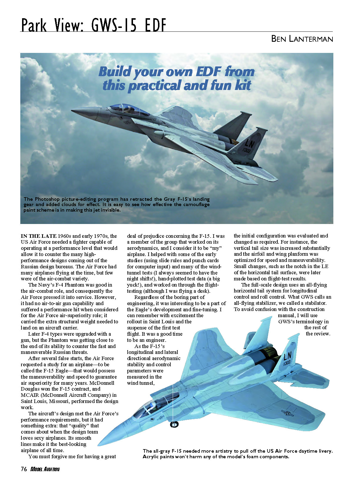
The aircraft’s design met the Air Force’s performance requirements, but it had something extra: that “quality” that comes about when the design team loves sexy airplanes. Its smooth lines make it the best-looking airplane of all time.
You must forgive me for having a great deal of prejudice concerning the F-15. I was a member of the group that worked on its aerodynamics, and I consider it to be “my” airplane. I helped with some of the early studies (using slide rules and punch cards for computer input) and many of the wind-tunnel tests (I always seemed to have the night shifts!), hand-plotted test data (a big yuck!), and worked on through the flight-testing (although I was flying a desk).
Regardless of the boring part of engineering, it was interesting to be a part of the Eagle’s development and fine-tuning. I can remember with excitement the rollout in Saint Louis and the suspense of the first test flight. It was a good time to be an engineer.
As the F-15’s longitudinal and lateral directional aerodynamic stability and control parameters were measured in the wind tunnel, the initial configuration was evaluated and changed as required. For instance, the vertical tail size was increased substantially and the airfoil and wing planform was optimized for speed and maneuverability. Small changes, such as the notch in the leading edge of the horizontal tail surface, were later made based on flight-test results.
The full-scale design uses an all-flying horizontal tail system for longitudinal control and roll control. What GWS calls an all-flying stabilizer, we called a stabilator. To avoid confusion with the construction manual, I will use GWS’s terminology in the rest of the review.
The final full-scale Eagle performs well over a large range of flight conditions and angles of attack. Even when the flight speeds are limited to those of our models, the F-15 should be stable and maneuverable. However, keep in mind that the F-15 wasn’t designed to perform sustained knife-edge flight or extremely tight rolling maneuvers.
Since I will never be able to afford a turbine-powered F-15 (engineering didn't pay that much), having a flying model of the aircraft seemed limited to something much smaller than I might develop on my own and would require a lot of work. When I saw the ads for the Grand Wing Servo F-15—the GWS-15—I immediately bought one.
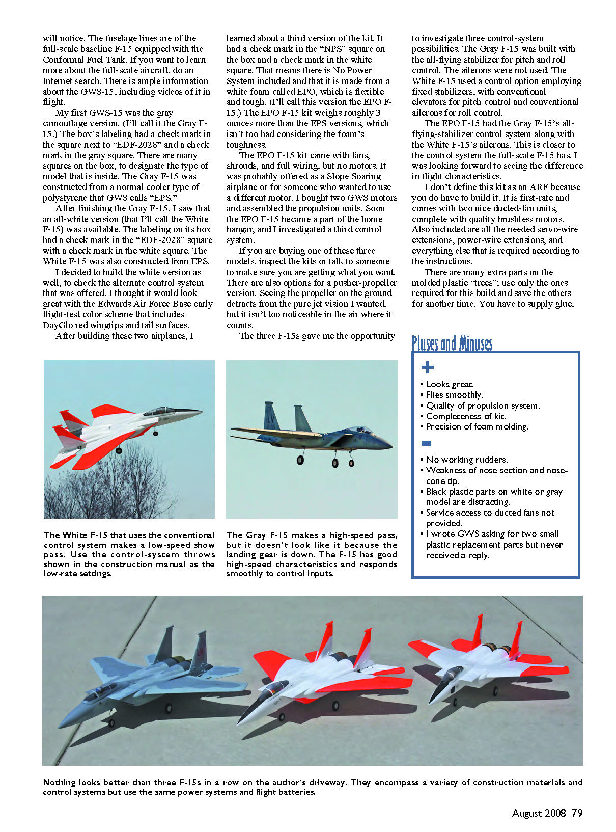
As I built the kit, I thought others would be interested in it, so I offered to write a review for MA. In the process of experimenting with different control systems and evaluating construction materials, I ended up buying three models! You can never have too many.
The Models
This F-15 is not exact scale, but it is close enough that no one except the most fanatical scale modeler with a ruler will notice. The fuselage lines are of the full-scale baseline F-15 equipped with the Conformal Fuel Tank. If you want to learn more about the full-scale aircraft, do an Internet search. There is ample information about the GWS-15, including videos of it in flight.
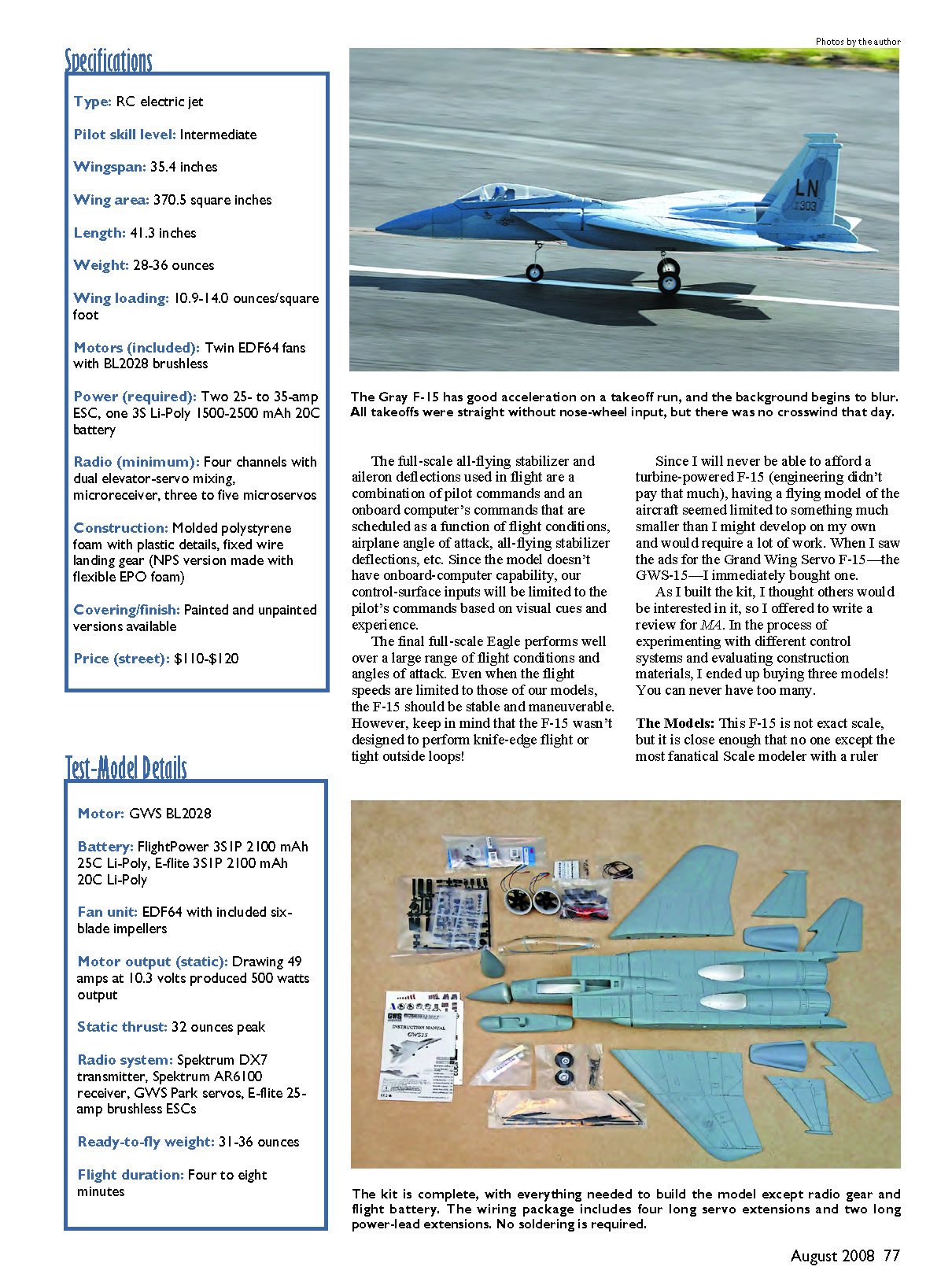
- Gray F-15: The first GWS-15 I built was the gray camouflage version (I'll call it the Gray F-15). The box's labeling had a check mark in the square next to "EDF-2028" and a check mark in the gray square. The Gray F-15 was constructed from a normal cooler-type polystyrene that GWS calls "EPS."
- White F-15: After finishing the Gray F-15, I saw that an all-white version (the White F-15) was available. Its box had a check in the "EDF-2028" square and the white square. The White F-15 was also constructed from EPS. I built the white version to check an alternate control system and to try an Edwards AFB early flight-test color scheme with DayGlo red wingtips and tail surfaces.
- EPO F-15: I later learned about a third version. The box had a check in the "NPS" square (No Power System included) and the white square. It is made from a white foam called EPO, which is flexible and tough. The EPO F-15 kit weighs roughly 3 ounces more than the EPS versions. The EPO kit came with fans, shrouds, and full wiring, but no motors. I bought two GWS motors and assembled the propulsion units.
There are also options for a pusher-propeller version, though seeing a propeller on the ground detracts from the pure-jet look. In the air it isn't too noticeable.
The three F-15s gave me the opportunity to investigate three control-system possibilities:
- Gray F-15: All-flying stabilizer for pitch and roll control; the ailerons were not used.
- White F-15: Fixed stabilizers with conventional elevators for pitch control and conventional ailerons for roll control.
- EPO F-15: A combination of the Gray F-15's all-flying stabilizer and the White F-15's ailerons—closer to the full-scale F-15 control system.
I don't define this kit as an ARF because you do have to build it. It is first-rate and comes with two nice ducted-fan units, complete with quality brushless motors. Also included are all the needed servo-wire extensions, power-wire extensions, and everything else required according to the instructions.
There are many extra parts on the molded plastic "trees"; use only the ones required for this build and save the others for another time. You have to supply glue, radio-control equipment, two ESCs, three or four servos (depending on the control options chosen), and flight batteries.
Equipment Used
I purchased all the F-15s and RC equipment I used in this review from my "RC modeling" cash fund. Being retired and finding that the cash fund is not a bottomless pit, I have to choose equipment based on quality and price. Other equipment will perform equally well.
I chose the Spektrum DX7 radio system for guidance. I have never had problems with my 72 MHz systems I used in more than 50 airplanes; however, I did manage to crash several park flyers while using them. I would get hot or distracted at the flying field and forget to change the transmitter's memory to the appropriate model name. Dumb, of course, but it did happen.
Spektrum's Model Match feature solved that problem: the receiver is bound to the particular model program, so you can't accidentally fly the wrong model program with the receiver. This is such a great feature that I purchased a second transmitter.
The model controlled with the all-flying stabilizer is designed to use GWS Park servos that fit precisely into the fuselage's premolded slots. Plastic fittings that couple the all-flying stabilizers to their driving servos are molded to fit the Park servo output spines. Using another servo would require a lot of adaptation. If you do use a different servo, be sure to check compatibility before permanently gluing anything. Almost any microservo will work with the conventional control layout; I used small JR servos since I had some and they fit the cutouts perfectly.
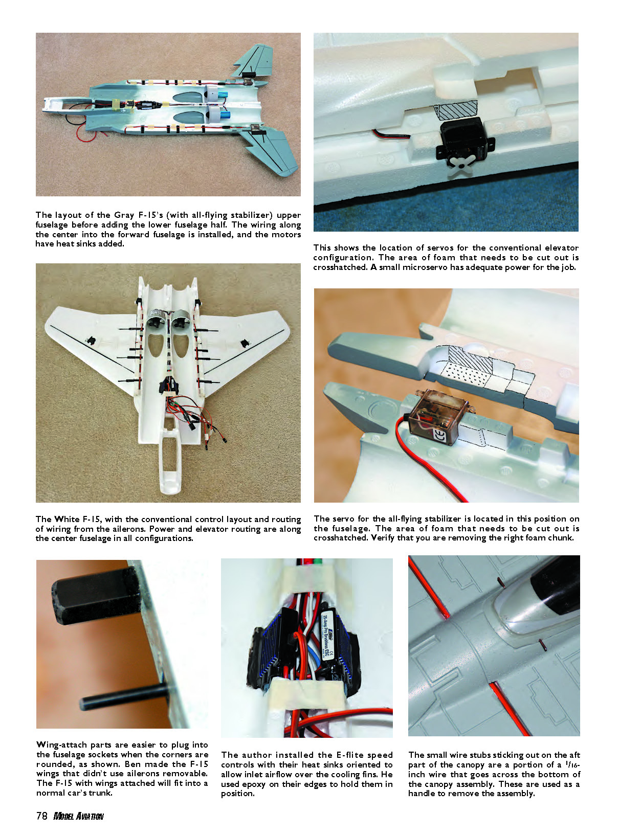
Since the propulsion system's current drain is close to 20 amps per motor and the ESCs may be mounted such that cooling air is limited, I chose the E-flite 25-Amp Pro Switch-Mode BEC Brushless ESC. It is a good compromise in price and capability and has a large heat sink to aid in cooling. I needed two of them: one for each motor.
The propulsion system's total current drain at the maximum power setting was probably going to be close to 40 amps, so a suitable-capacity three-cell Li-Poly battery was necessary. I chose the FlightPower EVO 25 2500 mAh Li-Poly battery (25C rating). I also bought the E-flite 2100 mAh Li-Poly battery (20C rating). Both batteries will be working within their advertised ratings. Don't try to use a low-rated 2100 mAh 10C battery; you won't get the necessary power and will likely destroy the battery.
Construction
The manual has a minimal number of words, but the drawings are clear. Pay attention to the areas where cutting foam for servos is required. Read carefully, look at the drawings, and then, with parts in hand, do a dry run of positioning and checking for interference, fits, etc. Then review everything again.
Make sure you are confident before proceeding to any step, because the conventional-control configuration and all-flying-stabilizer control configurations are intermixed within the manual. Because of the model's construction, it becomes next to impossible to go back and fix things once you glue the fuselage top to the fuselage bottom.
The wiring diagrams are well done, and you should have no problem setting up that part of the airplane.
The F-15 goes together nicely because everything fits well. A modeler who is experienced enough to fly the airplane should be able to work his or her way through the manual. However, there are several things that might make the build easier.
All the radio and propulsion parts are installed in the upper fuselage half, so you can fully check things out one last time before permanently gluing on the bottom fuselage half. The ducted fans fit into slotted areas, and the wiring for them and the servos are routed along the fuselage centerline. Cavities were molded to allow the wires to fit, but because I changed connectors, there isn't quite enough room for everything. You may have to remove a bit of foam to make things fit, but no strength loss is involved.
As you arrange the wiring for the servos and propulsion gear in the fuselage, use small pieces of tape to hold the wires in place. When all the wiring is positioned in the top, glue the bottom of the fuselage on and the rest of the assembly goes fairly quickly.
Before I started this project, I didn't care for the GWS glue. Although it hardens nicely, it has an extremely long working time and I get in a hurry. I changed my mind when I assembled the upper and lower fuselage halves; the adhesive provided the working time to do this properly.
I used the GWS glue on everything in the Gray F-15 and White F-15 assemblies and had no problems. They are molded from the standard GWS EPS material, which dissolves when almost any kind of glue or solvent other than the GWS adhesive is used. When using the GWS glue, plan your building schedule so that main glue interfaces, such as the top and bottom fuselage halves or main spar inserts, can set up overnight. It will make things seem to go quickly. Take the time while the glue is hardening to read the manual. The glue can also be used like a contact adhesive where applicable.
I constructed the EPO F-15 with regular cyanoacrylate glue. This type of foam doesn't melt with cyanoacrylate use, and I think the bond is better than with the GWS glue. Test any substitute glue on a noncritical, out-of-the-way area.
The wing flight loads are carried into the fuselage through three tube spars and one square spar. You can remove the wing by pushing on a tab attached to the square spar. I glued the socket parts into the fuselage and the plug parts into the wing without attempting to align them to each other; I just pushed each part firmly into its appropriate molded cavity. When I finally pushed the wing spars into the fuselage sockets, everything slid into place perfectly. However, when it's 95° and sweat is in your eyes at the flying field, it might be difficult to hit the holes. You can make wing attachment easier by sanding a semirounded point on the ends of the wing tubes and using a drill to slightly chamfer the holes in the fuselage sockets.
The canopy-latch mechanism was a tight snap fit when I checked it before installation. I had doubts that I could remove the canopy without damaging the canopy's foam base using the supplied parts. I finally gave up on the supplied latch parts and used 3/8-inch-diameter neodymium magnets to attach the canopy assembly. Just glue the magnets into the foam at the front and rear of the canopy with the appropriate glue or epoxy (remember to check foam/glue compatibility).
Some sort of handle at the aft part of the canopy is recommended to make removal easier. I glued a piece of 1/16-inch-diameter piano wire across the underside of the aft part of the canopy assembly and left approximately 1/4 inch to stick out on each side of the canopy base. I pull up on each of the nearly invisible wire ends to unlatch.
Don't forget to add a pilot before gluing the canopy on its base. It would be nice if GWS included a pilot bust in the kit.
I used the fixed-landing-gear option on all my F-15s. I have seen videos of awful hand launches of the model that demonstrated its great recovery characteristics. I thought it would be difficult to hand launch because of the large flat bottom and my small hands. The landing gear will work fine on the beautiful runway at the Boeing Phantom Flyers field.
The manual indicated that the CG should be 160 mm plus or minus 5 mm aft of the lower lip of the inlet. My F-15s' CGs came out within 1–2 mm of the required 160 mm mark when the ESCs were installed roughly halfway in the inlet ducting wall and with the battery installed.
The construction manual's diagrams do a nice job of illustrating the control-system setups. To set up the EPO F-15's configuration, I installed the all-flying stabilizer setup as used in the Gray F-15 and then put a servo splitter in the Spektrum AR6100 receiver AUX port for the aileron input. This may seem to make the aileron servos move in the same direction on the bench, but everything works in the appropriate direction when the servos are installed in the wing cutouts.
Make sure things work correctly before fixing the servos permanently in place. Set the initial control-surface throws to those shown for your setup in the manual.
The airplane looks good at this point, but it would be great if GWS included a bottle of touch-up paint in the gray kit. The existing paint film is thin and easily damaged during construction. Cover your building area with soft materials to protect the models.
I mixed some gray colors using artist's acrylic paint to touch up construction nicks and camouflage markings. Test any paint for foam compatibility, and wash the areas to be painted with alcohol or soapy water.
For the White F-15's Edwards Air Force Base flight-testing paint scheme, I used Faskolor acrylic Fastfluorescent Red that I bought at Mark Twain Hobbies in Saint Charles, Missouri. Having a hobby shop of this quality a few miles from my home is great. The prices are competitive, and the staff is knowledgeable and friendly.
I have one major complaint: the plastic parts used to mount the all-flying stabilizer and vertical tails were black—big, black, plastic, clunky parts. Why not mold them in a nice gray or white to match the airplane?
The construction manual presents a range of flying weights between 28.3 and 35.3 ounces. It suggests using a 1.3- to 1.8-amp-hour Li-Poly battery of greater than 15C capability for power. I think a battery with that low a capacity will have a hard time delivering the required power to the ducted fans.
The final weights of my models with no batteries were:
- Gray F-15: 32 ounces
- White F-15: 31 ounces
- EPO F-15: 36 ounces (extra weight due to the foam type)
Propulsion Tests
With a freshly charged battery capable of delivering full power to the system, the initial power input was roughly 500 watts (measured with an AstroFlight Wattmeter). That is 49 amps at 10.3 volts (voltage under full load). This voltage drop from the battery's fully charged resting voltage of more than 12 volts is typical of a Li-Poly battery delivering high power relative to its capacity. Power available throughout the motor run will be much less than these initial measurements as the battery discharges to the preset ESC cutoff voltage.
The initial measured static thrust was roughly 32 ounces. In-flight thrust will be less and will drop from about 30 to 20 ounces as speed increases. This thrust-to-weight ratio isn't too bad, and you do have maximum power at takeoff. You might be unable to hover and torque-roll, but this is a ducted-fan scale model of an F-15 for a reasonable price.
Flight Notes
Even with my rusty reflexes and the cold weather, I found the GWS F-15 to be delightful, fast, and smooth-flying in all configurations. The only problem I had was pulling back on the throttle once the F-15 was in the air. Although it flew nicely at lower speeds, it was way too much fun to perform the entire flight with full power.
My flight tests indicated that the control-surface throws recommended in the construction manual were well suited to the model at the recommended CG. Since the airplane didn't seem twitchy, you can fly it with a four-channel transmitter that doesn't have exponential capability. However, if you have that feature you can add exponential to suit your preferences as you gain experience with the airplane.
Takeoffs with the Gray F-15 and the EPO F-15 were smooth and easy to control. Setting the controls neutral so the all-flying stabilizer faired with the fixed part of the stabilizer mounted on the fuselage was a good starting point. The change in neutral control required for actual level flight was a bit of up-elevator trim. Roll trim setting was almost spot on; there was no problem in trimming the models.
During the White F-15's first takeoff with the conventional elevator for pitch control, I had the transmitter settings at the low rates and found I didn't have enough back stick to rotate the model. I had set the high-rate throw to the throw shown in the manual, and the low-rate throw was set to approximately half that—my mistake. I cut off the power and let it run into the grass at the end of the runway. In the process, the first 1/2 inch or so of the nose cone broke off.
Low control-rate throws should start at the manual's recommended settings. Then you can set the high throws higher than that.
When comparing the all-flying stabilizer (Gray F-15) to the all-flying-stabilizer-plus-aileron configuration (EPO F-15), I found that the all-flying stabilizer's roll-control authority is good enough that the ailerons aren't needed. The all-flying stabilizer also seems more effective in pitch control than the conventional elevator. I am looking forward to more experimentation with these control systems.
The Gray F-15's first landing was good, but it did run out onto the short grass at the end of the runway, resulting in roughly the first 1/2 inch of the nose cone breaking off, as happened with the White F-15. I didn't think the landing was too fast, but I was noticing a trend with the nose-cone tips. I didn't know grass was that hard, but it was freezing. The EPO F-15's landing was nice and smooth but a bit long; after a long runout it went into the grass. At least the nose cone stayed intact. So it wasn't the grass breaking the nose off; it was the weaker EPS foam.
This should lead to a suggested kit modification: replace the nose cones made from the Styrofoam-type material with EPO.
Another incident resulted in a fuselage broken in half midway under the canopy. This happened when my helper picked up the White F-15 incorrectly. Most helpers and modelers have learned to pick up a model with one hand under the wing or fuselage near the CG and the other hand on the nose to steady the airplane. We might lift with considerable force on the nose because it is often the strongest part of the model. When you do that with this F-15, it puts pressure on the nose in the weakest part until it breaks at a point approximately halfway back from the front of the canopy.
I will use carbon-fiber mat or something similar with epoxy to strengthen the inside of the fuselage on each side along this area. I recommend that you do so too.
I really do like this model—how it looks and how it flies. I recommend it to any experienced flier.
Ben Lanterman [email protected]
Manufacturer/Distributor
Grand Wing System U.S.A. Inc. 138 S. Brent Cir. City of Industry, CA 91789 (909) 594-4979 www.gwsus.com
Sources
- E-flite
(800) 338-4639 www.e-fliterc.com
- FlightPower
(800) 637-7660 www.bestrc.com/flightpower/
- Spektrum
(800) 338-4639 www.spektrumrc.com
Online Forum and Video
www.rcgroups.com/forums/showthread.php?t=682816
Other Review Articles
- Aviation Modeler International: May 2008
- Quiet Flyer: December 2007
Transcribed from original scans by AI. Minor OCR errors may remain.

