

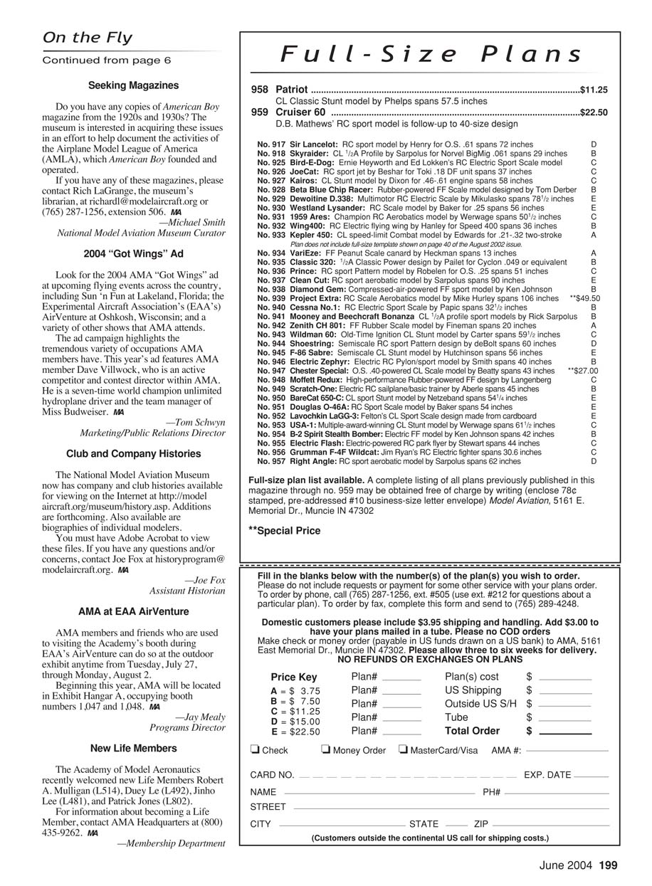
PATRIOT
CL Classic Stunt model boasts World Championships heritage
by Gerry Phelps
Did you ever have a great piece of balsa wood that you just couldn’t bring yourself to use, because once you used it, it would be gone? How’s that for warped logic?
I have such a piece of balsa. It’s a light block, approximately 4 inches square and roughly 40 inches long. I’ve had it since the late 1960s and have carried it with me through several moves. I was away from modeling from 1973 through 1987, and I still kept lugging that piece of balsa around.
This article is not really about an old block of balsa. It’s about a Stunt-model design that I flew from 1969 through 1971: the Patriot. I tell the balsa story because it parallels my reluctance to recreate the Patriot design. Since getting back into flying Stunt in 1988, I planned to re-create the Patriot someday, but I figured that once I had built it I would no longer have the project to look forward to. What if it didn’t fly as well as I remembered? I thought I’d be disappointed. Boy, was I wrong.
I began remaking the Patriot in the fall of 2001 and finished it in time to take it to the March 2002 Vintage Stunt Championships (VSC) in Tucson, Arizona—unflown, I might add. I had more fun that week than I had had in a long time. The engine (a Randy Smith AeroTiger .36) ran great, and the airplane flew wonderfully right off the board with no adjustments. That’s rare.
The airplane drew quite a bit of attention, and I received many positive comments from the other contestants. I was wrong not to have built this Classic design sooner, and I regret waiting as long as I did. You know what? I’m going to use that light balsa block the next chance I get—perhaps on another Patriot.
Design Origin
In the fall of 1968 I began thinking about what I might build during the winter for the next flying season. Having built several Fox .35-powered I-Beam airplanes and Noblers throughout the years—and based on what was becoming a trend toward slightly larger airplanes—I wanted something a little bigger. At that time, several of my friends were having success with the venerable McCoy .40 in the somewhat larger designs.
Although the McCoy .40 did not hold up well if exposed to even one extended lean run, it did appear to offer the best Stunt-run characteristics and power for that displacement. So a McCoy .40 it was.
Several jet-type designs showed up during that time period, and Jim Kostecky’s were the most inspiring to me—especially his Formula S. With what I thought to be the Formula S’s best appearance characteristics in mind, I drew a set of plans. I incorporated the forward canopy, the air-intake scoops at the wing root, and the jet-style fin and rudder into the design.
When I finished the first airplane built from those plans in the spring of 1969, it wore a Thunderbird paint scheme but did not have a name. It weighed 43 ounces and performed quite well. However, I regretted having made equal wing panels for the initial design. The model began life with a 56-inch wingspan, but I had enough leadout material exposed to significantly extend the inboard wing, and I did just that. I removed the inboard tip and added 1.5 inches to the span, bringing it up to 57.5 inches. Hoping I wouldn’t be asking too much from the McCoy .40, that modification turned a good airplane into a great airplane. It grooved well, turned well, and stayed out on the lines.
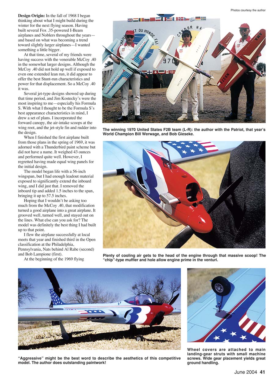
I flew the airplane successfully at local meets that year and finished third in the Open classification at the Philadelphia Nats behind Al Rabe (second) and Bob Lampione (first). At the 1969 Nats Bob Gieseke encouraged me to attend the Team Trials for the 1970 World Championships in Namur, Belgium. I made the team and placed first in the team-selection competition. That was my "shining moment" in CL Stunt.
For the 1970 world competition I built the same design with a splashy USA paint scheme and the name "Patriot." With a light-blue base coat I added stars and stripes. The 1970 airplane flew great and handled much like the 1969 airplane. The Patriot and I finished fourth at the 1970 World Championships (Bill Werwage first, Bob Gieseke second, and Czechoslovakia’s Gabris third). The U.S. team finished first.
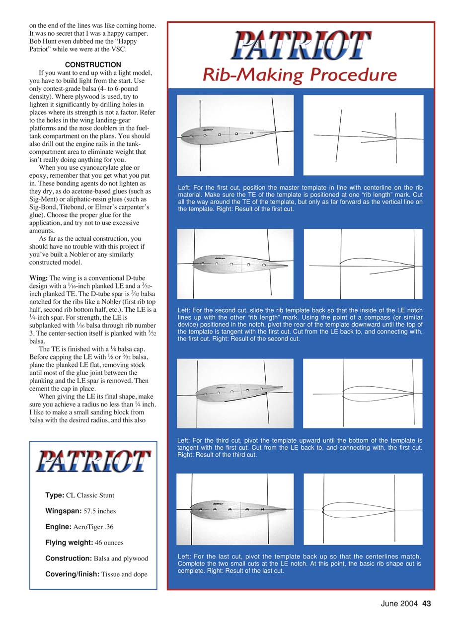
My 2002 model has the exact paint scheme I used on the 1970 airplane that went to Belgium. Using the original trim, name, and AMA-number stencils I made in 1969/1970, I re-created the colorful trim as accurately as possible. I even duplicated the cockpit detail from plan detail and an old close-up photo of the 1969 cockpit that I got from Jack Sheeks a few years ago.
Seeing it out there in the air made me almost feel as if I had stepped back in time. The airplane performed exactly as I remembered—grooving and turning smoothly, and staying out on the lines. Being on the end of the lines was like coming home. Bob Hunt even dubbed me the "Happy Patriot" while we were at the VSC.
Specifications
- Type: CL Classic Stunt
- Wingspan: 57.5 inches
- Engine: AeroTiger .36
- Flying weight: 46 ounces
- Construction: Balsa and plywood
- Covering/finish: Tissue and dope
CONSTRUCTION
If you want to end up with a light model, you have to build light from the start. Use only contest-grade balsa (4- to 6-pound density). Where plywood is used, lighten it by drilling holes in places where strength is not required—refer to the holes in the wing landing-gear platforms and the nose doublers in the fuel-tank compartment on the plans. Drill out the engine rails in the tank-compartment area to remove unnecessary weight.
When you use cyanoacrylate glue or epoxy, remember that you get what you put in. These bonding agents do not lose weight as they cure, unlike acetone-based glues (such as Sig‑Ment) or aliphatic-resin glues (such as Sig‑Bond, Titebond, or Elmer’s carpenter’s glue). Choose the proper glue for the application, and avoid excessive amounts.
If you’ve built a Nobler or any similarly constructed model, you should have no trouble with this project.
Wing
- The wing is a conventional D-tube design with a 1/16-inch planked leading edge (LE) and a 3/32-inch planked trailing edge (TE).
- The D-tube spar is 3/32 balsa notched for the ribs like a Nobler (first rib top half, second rib bottom half, etc.).
- The LE spar is 1/4 inch. For strength, the LE is subplanked with 1/16 balsa through rib number 3. The center section itself is planked with 3/32 balsa.
- The TE is finished with a 1/8 balsa cap. Before capping the LE with 1/8 or 3/32 balsa, plane the planked LE flat, removing stock until most of the glue joint between the planking and the LE spar is removed. Then cement the cap in place.
- When giving the LE its final shape, achieve a radius no less than 1/4 inch. I make a small sanding block from balsa with the desired radius to get a smooth, consistent shape.
The procedure for making this model’s ribs is a bit different from what you may be used to; see the rib-making procedure below. Photos in the original article show the layout on white card stock for clarity; in practice, lay the ribs out on the actual balsa rib stock.
Wingtips start as a piece of 1/16 balsa (see plans for hole locations to lighten) with edges laminated with scrap 1/64 balsa, top and bottom. Once cemented in place, notch the laminations to accept 1/16-inch planking at the LE and 3/32 inch at the TE. Leave the wing TE planking long during wing construction, then pinch it together and cement it into notches in the wingtip edge laminations.
Before installing the wingtip ribs, contour and taper the tip laminations so they blend with the end wing rib. Use a large sanding block and a straightedge to check for surface continuity, and aim for an approximately 1/4-inch rounded edge along most of the tip’s perimeter. Install and block-sand the tip ribs to match the tip surface contour. The 2002 model has a tip weight box and an adjustable leadout guide; these are optional.
The original models had 3-inch bellcranks; I chose a Brodak 4-inch nylon bellcrank for the 2002 model. Installation is conventional with a plywood floor. For added strength, support the top of the bellcrank bolt with another section of plywood running to the first inside panel rib and reinforce it appropriately to the spar and center-section planking.
Make the flaps from 1/4 balsa and taper them to approximately 1/8-inch thickness at the TE. I make my own control horns, but there are quality ready-made products available. The original models had handmade plywood and piano-wire hinges as shown on the plans; I chose tissue taffeta hinges (100% polyester) for the 2002 model to achieve a totally sealed hinge line. Conventional nylon hinges are another option.
If you use cloth hinges, make sure they are 100% polyester. Even if the material is labeled 100% polyester, test it before use: apply a few drops of thin cyanoacrylate to a test piece, allow it to dry thoroughly, bend it back and forth several times, and tug at it to make sure it will not fatigue and fail.
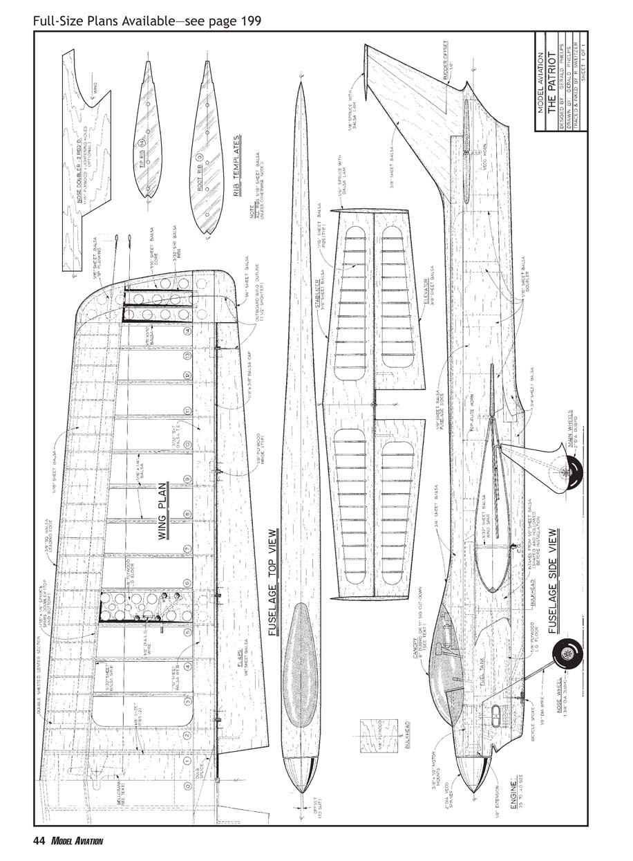
Rib-making procedure
Note: the procedure below describes four cuts to produce the basic rib shape using a master template. Lay out the template on the rib stock so the TE of the template is at one “rib length” mark and follow these steps.
- First cut
- Position the master template in line with the centerline on the rib material. Make sure the TE of the template is positioned at one "rib length" mark.
- Cut all the way around the TE of the template, but only as far forward as the vertical line on the template. Result: the TE is defined and the forward area is left uncut.
- Second cut
- Slide the rib template back so that the inside of the LE notch lines up with the other "rib length" mark.
- Using a pivot point placed in the notch (a compass point or similar), pivot the rear of the template downward until the top of the template is tangent with the first cut.
- Cut from the LE back to, and connecting with, the first cut. Result: one forward cut is made, defining part of the LE.
- Third cut
- Pivot the template upward until the bottom of the template is tangent with the first cut.
- Cut from the LE back to, and connecting with, the first cut. Result: the other forward contour cut is made.
- Fourth (final) cut
- Pivot the template back up so that the centerlines match. Complete the two small cuts at the LE notch.
- At this point the basic rib shape is complete. Final sanding and trimming produce the finished rib.
Empennage
- Cut the stabilizer and elevator from 3/8-inch balsa sheet, shape to achieve the cross-section foil shown on the plans, then hollow them as shown on the planform. Add the 1/16-inch ribs.
- I covered the original versions with medium-weight silkspan, which provided adequate strength. For the 2002 model I covered almost the entire airplane with light plyspan (Sig Japanese tissue). To strengthen the stabilizer I used two layers of medium plyspan.
- Another strengthening method is to cement thin unidirectional carbon tape to the inside of the stabilizer cutout area before installing ribs, running the carbon out from the center approximately 5 inches before installing the ribs.
- On the new model I applied a layer of thin carbon mat on the top and bottom of the stabilizer’s TE; the rudder and fin are also made from 3/8-inch sheet balsa and covered with thin carbon mat for strength. Carbon mat was also used on the flaps for rigidity and on the nose for durability.
Fuselage
- The fuselage uses conventional construction: 1/8-inch sides, 1/16-inch plywood nose doublers, and adequately placed bulkheads. Bulkheads are built up.
- Glue 1/16-inch balsa strips about 1/2 inch wide vertically to the inside of each fuselage side as indicated on the planform. Invert the fuselage sides and place them on a flat building surface for further assembly.
- Using a centerline on the building surface, complete the tank-compartment area first when joining the halves. Cut and install horizontal bulkhead stringers in the remainder of the fuselage where the 1/2-inch vertical bulkhead strips are located, achieving the width shown on the planform. These stringers can be made from 1/8 or 3/16 balsa and need only be roughly 3/8 inch wide.
- Temporarily remove the fuselage side sections under the wing for wing installation. Use top and bottom blocks to achieve desired shapes, and then hollow them to a wall thickness of approximately 1/8 inch.
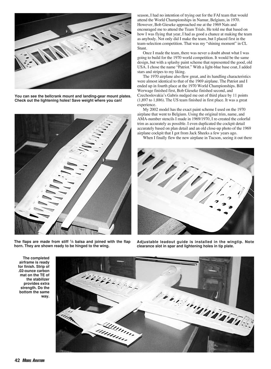
- Build the cowl from sheet and blocks, then shape and hollow it. I use an old cowl-hold-down technique: a bicycle spoke and a spoke nut. It works well and presents nicely.
- I cut the canopy from a Sig 11-inch bubble and soaked it in blue Rit dye to achieve the desired tint.
Finish
I finished the 2002 model with Brodak dope and was extremely satisfied with the results. The model won the pilots’ choice (Concours) award at the 2002 Vintage Stunt Championships.
Much has been written about finishing, so I won’t elaborate on my technique here. Whatever finish approach you use, I can’t stress enough the importance of keeping the weight down.
If you build this model light and straight, you will absolutely love the way it flies. Have fun, and let me know what you think of your Patriot. I think I hear my balsa block calling me.
Gerry Phelps 4175 Sacramento Blvd. Medina, OH 44256
Editor’s note
Gerry is one of the rare CL Stunt pilots who flies his models clockwise (when the model is upright). Because of that, his control system is set up with the leadouts running out the right wing. His plan drawing depicts this preference and shows the right wing panel as the longer of the two. If you fly the other way, build the left wing as the longer wing and reverse the control system as depicted on the plans.
Transcribed from original scans by AI. Minor OCR errors may remain.

