
Pea Patch
PIETENPOL, Corben, Huntington, Heath, Long, Wittman: names that recall the early days of aviation, that intoxicating era known in the lexicon of flight as the Golden Age. During the late Twenties and early Thirties, these pioneers of the home-built aircraft movement took to designing, building, and flying their own creations out of pastures, grass airports, and any fields that were available. They had many imitators, and the activity caught on quickly.
Air racing, too, was popular during those years. Aviation buffs are familiar with the Howard-designed Ikes, Mikes, and Mulligans, the Gee Bee series produced by the Granvilles, and others.
The early home-building movement came to a premature end during the mid-30s, unable to survive a weakened Depression economy and increasing federal legislation. Building a personal airplane and flying it out of a pasture came to be almost a thing of the past.
But home-builders had never lost enthusiasm for their hobby, and in 1953 a young aviator named Paul Poberezny took steps to revive it. Poberezny, a designer, builder, and flier, returned from aviator duty over Korea with the Wisconsin Air National Guard and organized a gathering of 33 home-builders at Curtiss-Wright Airport in Milwaukee. From that meeting sprang the beginnings of what is now a world-class aviation organization. With its aviation center and museum at Oshkosh serving as a focal point for home-builders, the Experimental Aircraft Association has literally saved the movement from vanishing altogether.
A quick glance at unlimited aerobatics worldwide shows that home-building isn't restricted to small, low-powered personal aircraft. In 1980 the United States' Leo Loudenslager flew his home-built Laser 200 to win the World Aerobatics Championships against the best from around the globe with their government-sponsored craft.
Another U.S. home-builder, Henry Haigh, snared the 1988 championships; his Super Star with its own-designed and -built Akro mount outperformed rival factory-built models using more exotic materials.
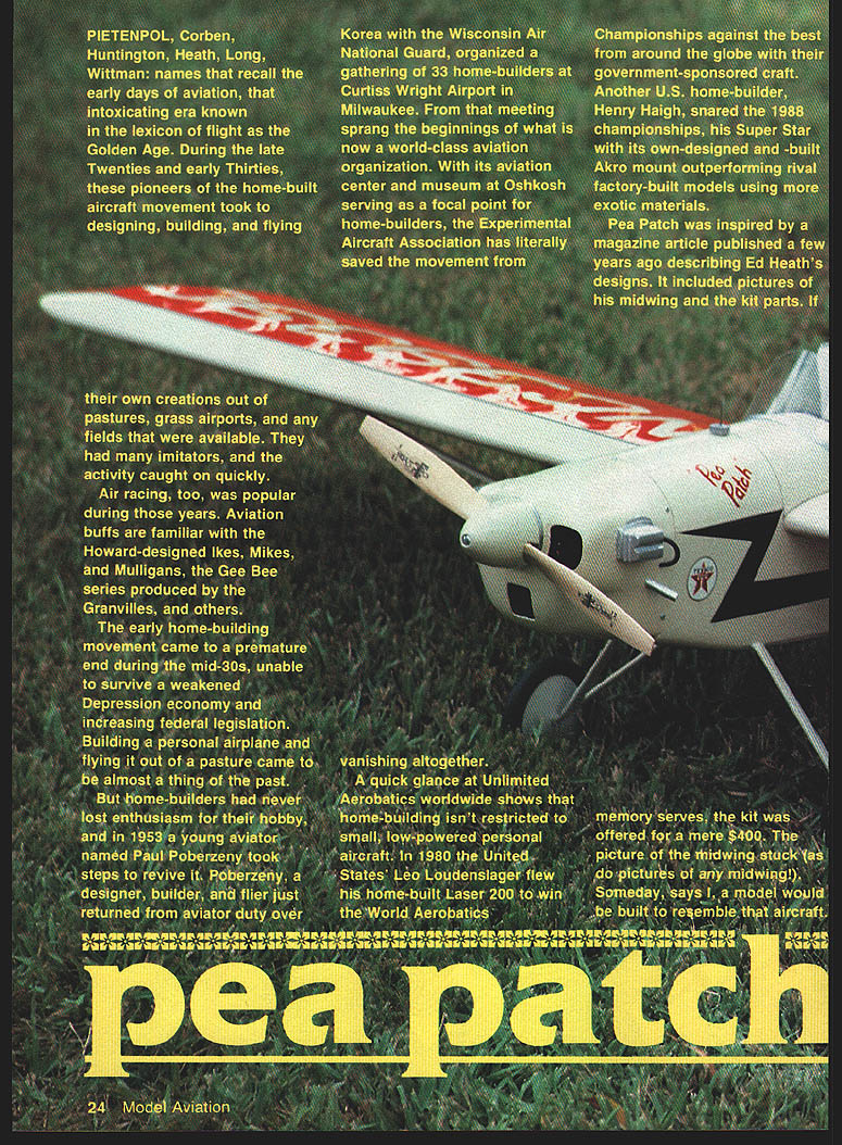
Pea Patch was inspired by a magazine article published a few years ago describing Ed Heath's designs. It included pictures of his midwing and the kit parts. If memory serves, the kit was offered for a mere $400. The picture of the midwing stuck (as do pictures of any midwing!). Someday, says I, a model would be built to resemble that aircraft.
I happened to have an O.S. .40FS that was lying idle, a perfect choice to capture the looks and sound of the vintage home-builts. With no three-view to go by, I worked out some numbers based on the O.S. installation. I also incorporated aerobatic capacity in the final design, so that it surpassed pioneer-era performance.
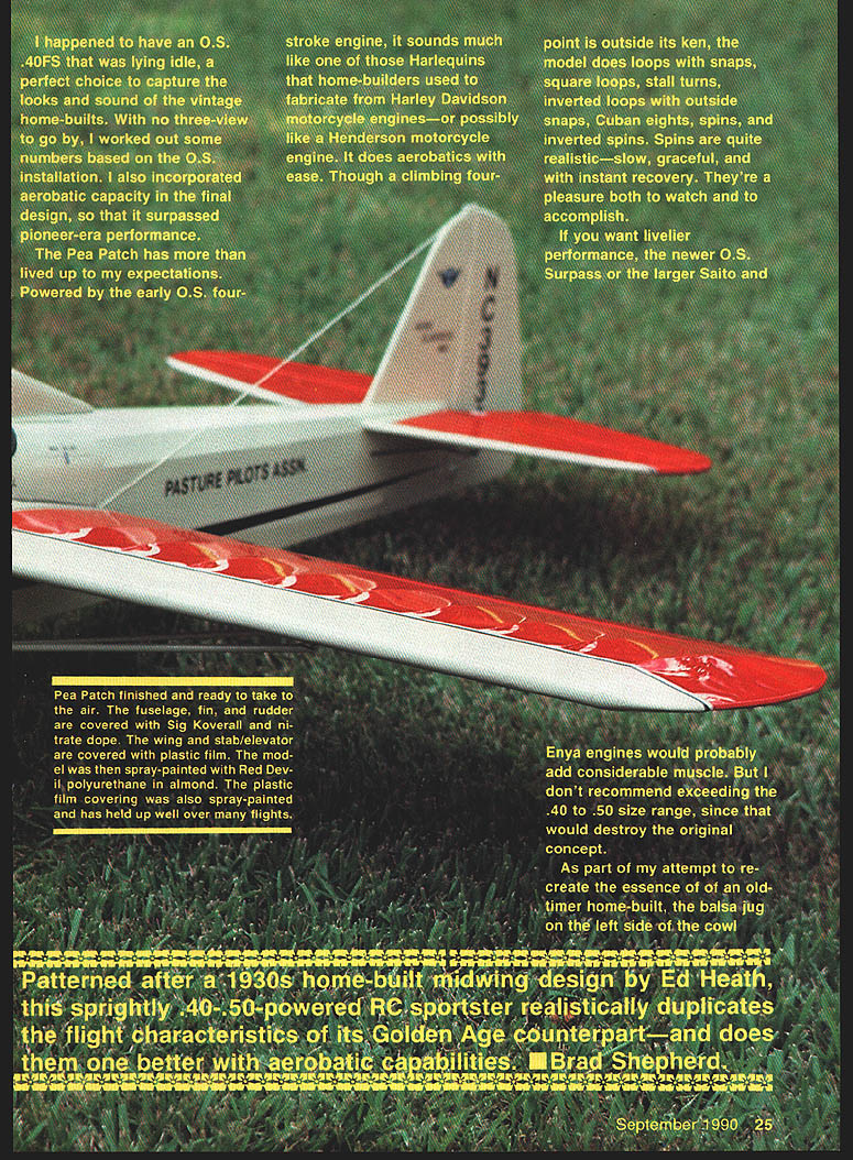
The Pea Patch has more than lived up to my expectations. Powered by the early O.S. four-stroke engine, it sounds much like one of those Harlequins that home-builders used to fabricate from Harley-Davidson motorcycle engines—or possibly like a Henderson motorcycle engine. It does aerobatics with ease. Though a climbing four-point is outside its ken, the model does loops with snaps, square loops, stall turns, inverted loops with outside snaps, Cuban eights, spins, and inverted spins. Spins are quite realistic—slow, graceful, and with instant recovery. They're a pleasure both to watch and to accomplish.
If you want livelier performance, the newer O.S. Surpass, or the larger Saito and Enya engines would probably add considerable muscle. But I don't recommend exceeding the .40 to .50 size range, since that would destroy the original concept.
As part of my attempt to re-create the essence of an old-timer home-built, a balsa jug was added to the left side of the cowl.
Patterned after a 1930s home-built midwing design by Ed Heath, this sprightly .40-.50-powered RC sportster realistically duplicates the flight characteristics of its Golden Age counterpart—and does them one better with aerobatic capabilities. — Brad Shepherd
Tips before building
- For sure accuracy when building the panels, tracings can be made of the formers, glued to the wood with spray contact cement, and peeled off after the formers are cut out.
Wing
- Pin a 1/4-in.-sq. stick in place over the plans to be used as a jig. Pin another 1/4-in.-sq. stick under the bottom spar, and pin the spar to the board.
- Position the ribs on the spar, and pin them to the jig and spar. Position the top 1/4-in. spar, slide the 1/8 x 1/2-in. trailing edge in place, then slide the 1/4 x 1/2-in. rear spar through the ribs.
- Check the panel with a yardstick or a Sig straightedge. If it looks accurate, apply thick CyA (cyanoacrylate glue) on all the joints.
- Glue the 1/4 x 1/2-in. leading edge piece to the ribs, and sand a bevel to conform to the rib shape. Cover the leading edge with 1/16-in. sheet balsa.
- Cut the rear spar to length. Unpin the panel, turn it over, and pin it back down on the jig and at each rib. Sand a bevel in the leading edge, and install the bottom sheeting. Glue 1/16-in. verticals to the spars while the panel is still pinned down.
- Glue the 7/16-in. tip pieces together, and install them on the center of the W-2 leading and trailing edges. Install the braces, spar extensions and sheet tip.
- Sand a bevel on the edge of the 1/4 x 3/8-in. balsa aileron spar, and pin it to the 1/4-in. trailing edge. Pin the aileron ribs onto the 1/4 x 1-in. trailing edge. With this assembly in place over the plans, glue with CyA.
- Install and glue the 1/4-in.-sheet horn mount flush with the bottom wing assembly.
Wing assembly:
- Draw a straight line at least 65 in. long on your workbench. Place the dihedral jig at the outboard W-2 position to align the spar mark with the bench line.
- Put plastic wrap or waxed paper under the center section, then check the fit of the spars and the leading and trailing edges. When you're satisfied that they're square, place shims under the trailing edge and pin the panel down.
- Install and epoxy the DB pieces to the spars, and the SJ pieces to the rear spar. Glue a 1/4-in.-sq. piece to the front edge of the trailing edge halves.
- Sheet the center section while the wing is still on the bench. After sheeting, remove the wing and install the aileron crank mounts. Glue the mounts to the cutouts in the W-3A ribs. Connect the 1/16-in. music wire pushrods to the aileron cranks. Sheet the bottom center section.
- Glue the 1/4 x 5/16-in. leading edge cap in place, and sand it round.
Stabilizer, elevator, rudder and fin
- Build the stabilizer, elevator, rudder and fin over the plan. Make the elevator tie bar, epoxy the elevator halves together, and sand to shape.
- Install hinge locations and hinges as shown on the plans.
Fuselage
- Glue the Lite Ply doublers and 1/8-in. balsa sides together to make a right and left assembly. Take care: don't assemble both sides the same way; the balsa must be on the outside of each piece.
- Pin the right side over the plan and finish building the balsa sticks indicated. Cover glue joints with strips of waxed paper.
- Position the left-side doubler assembly over the plan, bring the tail posts together and clamp the unit with clothespins, setting up on the bench.
- Install F-2 slots, shimming under the sides where necessary to keep former locations true. Epoxy the formers and doublers using blocks to hold the sides in place while the glue dries.
- Glue the top and bottom crosspieces in place, pin top formers aft of F-3 temporarily. Install formers F-2 and F-3, making sure the slots and doublers are aligned. Epoxy the motor mounts and firewall per the plans.
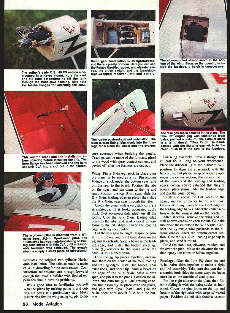
- Install servo mounts and radio gear in the fuselage. There is plenty of room; fit the throttle, rudder and elevator servos, the on/off switch, receiver and battery as shown in the plans. The side-mounted aileron servo installs in the bottom of the wing; because the opening is inside the fuselage, a hatch is unnecessary.
- Fit the cowl and mock up the left-hand balsa engine jug if using the scale balsa jug detail. The exhaust stack is a 1/4-in. dowel. Paint and detail per the plans.
Additional fuselage assembly notes:
- For the cabin section sheeting, cut six pieces of 1/8-in. sheet balsa at least 4-1/2 in. long from three wide sheets of A-grain balsa. This type of balsa will curve easily along its length (with the grain). Soak the pieces in water, then wrap them around coffee cans, liberally secured with rubber bands, until they're dry.
- Glue in the 1/16-in. balsa side doublers, the 1/8-in. side stringers, the saddle strip, and the 1/8 x 1/8-in. strip on the top longeron.
- Epoxy the Lite Ply WP in the cutouts on the ply doubler and against F-3. Epoxy the WPB reinforcements in place. Cut three lengths of Sig maple engine mount stock to size, and epoxy in place as per the plans.
- Position the wing in the saddle, then sand away any high spots in the saddle so that the wing fits snugly on the fuselage. Pin the wing at the trailing edge, squaring it up with the tail post.
- Drill down through the wing ply plate, WP and the maple block with a 1/8-in. drill. Install a short piece of 3/16-in. dowel in the hole. Drill one of the front holes through the ply plate and maple block, and install a second piece of doweling. Drill the remaining hole.
- After removing the wing, tap the blocks for 1/4-20 and enlarge the holes in the wing to 1/4 in. Bolt the wing in place, and lay plastic wrap over the center section. Pin the 3/8-in. cabin strips and the formers in place.
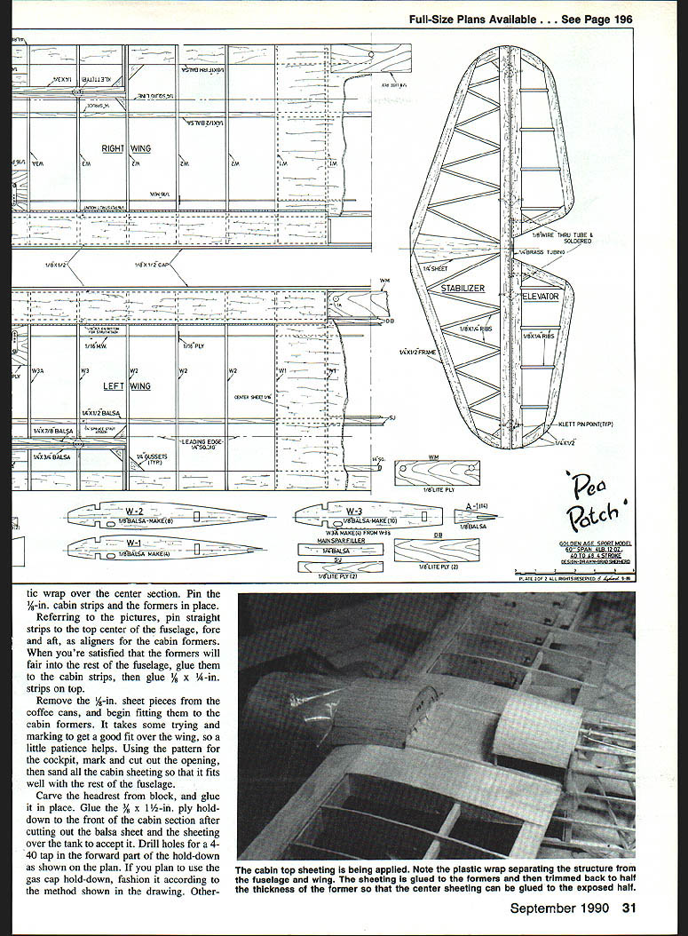
- Referring to the pictures, pin straight strips to the top center of the fuselage, fore and aft, as aligners for the cabin formers. When you're satisfied that the formers will fair into the rest of the fuselage, glue them to the cabin strips, then glue 1/8 x 1/4-in. strips on top.
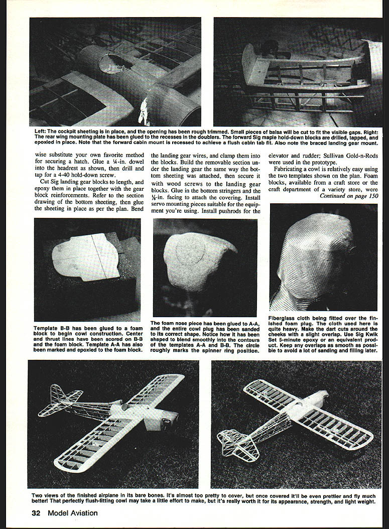
- Remove the 1/8-in. sheet pieces from the coffee cans, and begin fitting them to the cabin formers. It takes some trying and marking to get a good fit over the wing, so a little patience helps. Using the pattern for the cockpit, mark and cut out the opening, then sand all the cabin sheeting so that it fits well with the rest of the fuselage.
- Carve the headrest from block, and glue it in place. Glue the 3/8 x 1-1/2-in. ply hold-down to the front of the cabin section after cutting out the balsa sheet and the sheeting over the tank to accept it. Drill holes for a 4-40 tap in the forward part of the hold-down as shown on the plan. If you plan to use the gas cap hold-down, fashion it according to the method shown in the drawing. Otherwise, substitute your own favorite method for securing a hatch.
- Glue a 1/4-in. dowel into the headrest as shown, then drill and tap for a 4-40 hold-down screw.
- Cut Sig landing gear blocks to length, and epoxy them in place together with the gear block reinforcements. Refer to the section drawing of the bottom sheeting, then glue the sheeting in place as per the plan. Bend the landing gear wires, and clamp them into the blocks.
- Build the removable section under the landing gear the same way the bottom sheeting was attached, then secure it with wood screws to the landing gear blocks. Glue in the bottom stringers and the 3/8-in. facing to attach the covering.
- Install servo mounting pieces suitable for the equipment you're using. Install pushrods for the elevator and rudder; Sullivan Gold-n-Rods were used in the prototype.
Mark off and drill holes for the engine mount on the F-1 firewall. The author used 6-32 bolts through the firewall, epoxied to the back side with lengths of wire in the head slots. Install the firewall, and epoxy it to the doublers.
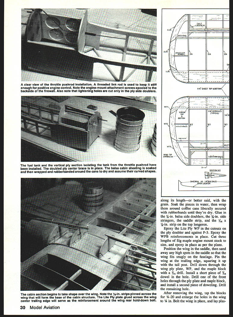
Install the pushrod for the engine throttle at this point. The picture shows the installation for an O.S. .40. Install the Lite Ply mounting in the tank compartment and the vertical piece to isolate the throttle pushrod. Install the tank, and pack foam around it. Glue the top doubler 1/8 x 1/2-in. Lite Ply pieces to slots in F-1 and F-2. Glue on the 1/8-in. sheet top.
Cowl
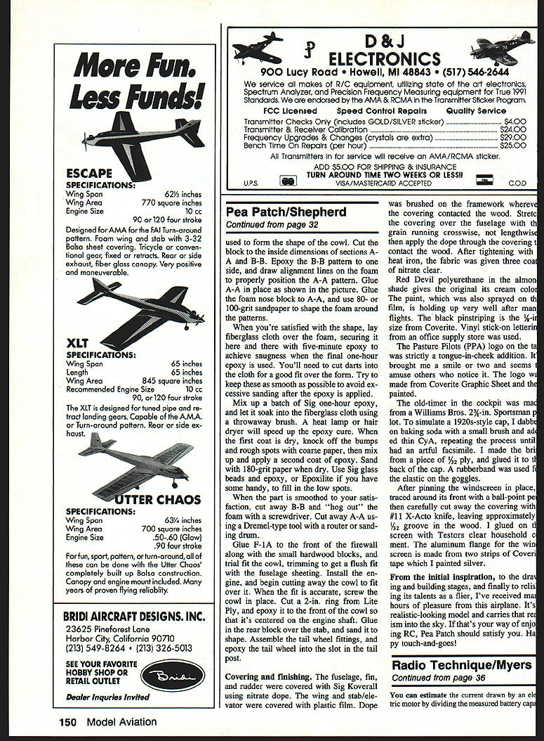
- Fabricating a cowl is relatively easy using the two templates shown on the plan. Foam blocks, available from a craft store or the craft department of a variety store, were used to form the shape of the cowl. Cut the block to the inside dimensions of sections A-A and B-B.
- Epoxy the B-B pattern to one side, and draw alignment lines on the foam to properly position the A-A pattern. Glue A-A in place as shown in the picture. Glue the foam nose block to A-A, and use 80- or 100-grit sandpaper to shape the foam around the patterns.
- When you're satisfied with the shape, lay fiberglass cloth over the foam, securing it here and there with five-minute epoxy to achieve snugness when the final one-hour epoxy is used. You'll need to cut darts into the cloth for a good fit over the form. Try to keep these as smooth as possible to avoid excessive sanding after the epoxy is applied.
- Mix up a batch of Sig one-hour epoxy and let it soak into the fiberglass cloth using a throwaway brush. A heat lamp or hair dryer will speed up the epoxy cure. When the first coat is dry, knock off the bumps and rough spots with coarse paper, then mix up and apply a second coat of epoxy. Sand with 180-grit paper when dry. Use Sig glass beads and epoxy, or Exponite if you have some handy, to fill in the low spots.
- When the part is smoothed to your satisfaction, cut away B-B and "hog out" the foam with a screwdriver. Cut away A-A using a Dremel-type tool with a router or sanding drum.
- Glue F-1A to the front of the firewall along with the small hardwood blocks, and nail the cowl, trimming to get a flush fit with the fuselage sheeting. Install the engine, and begin cutting away the cowl to fit over it. When the fit is accurate, screw the cowl in place.
- Cut a 2-in. ring from Lite Ply, and epoxy it to the front of the cowl so that it's centered on the engine shaft. Glue in the rear block over the stab, and sand it to shape. Assemble the tailwheel fittings, and epoxy the tailwheel into the slot in the tail post.
Final assembly
- Install the stabilizer and fin, dry-fitting and checking for straightness and alignment. Install pushrods and control linkages, checking for free movement and correct throws.
- Balance the model at the recommended CG location, and add ballast if required.
- Finish covering and paint as desired. Make up any final cowling and surface details, install the chosen engine (the model flies well on .40-.50 two-stroke or small four-stroke engines), and perform the usual preflight checks before the first flight.
Covering and finishing
- The fuselage, fin, and rudder were covered with Sig Koverall using nitrate dope. The wing and stab/elevator were covered with plastic film. Dope was brushed on the framework wherever the covering contacted the wood.
- Stretch the covering over the fuselage with a heat gun, running crosswise, not lengthwise, then apply the adhesive through heat to contact the wood. After tightening with a heat iron, the fabric was given three coats of nitrate clear.
- Red Devil polyurethane in the almond shade gives the original its cream color. The paint, which was also sprayed on the film, is holding up very well after many flights. The black pinstriping is the 1/8-in. size from Coverite. Vinyl stick-on letters from an office supply store were used.
- The Pasture Pilots (PPA) logo on the cowl was strictly a tongue-in-cheek addition. It brought me a smile or two and seems to amuse others who notice it. The logo was made from Coverite Graphic Sheet and then painted.
- The old-timer in the cockpit was made from a Williams Bros. 2-1/2-in. Sportsman pilot. To simulate a 1920s-style cap, I dabbed on baking soda with a small brush and then C.A., repeating the process until I had an effect of facial grime. I made the belt from a piece of 1/2-in. ply, and glued it to the edge of the cap. A rubber band was used for the elastic on the goggles.
- After pinning the windscreen in place, trace around its front with a ball-point pen then carefully cut away the covering with a #11 X-Acto knife, leaving approximately a 1/32-in. groove in the wood. I glued on the screen with Testors clear household cement. The aluminum flange for the wing strut is made from two strips of Coverite tape which I painted silver.
From the initial inspiration, to the drawing and building stages, and finally to the airplane's flying, I've received many hours of pleasure from this airplane. It's a realistic-looking model and carries that look of the era. After that many hours of building, the Pea Patch should satisfy you. Have fun with touch-and-goes!
Plans and drawings
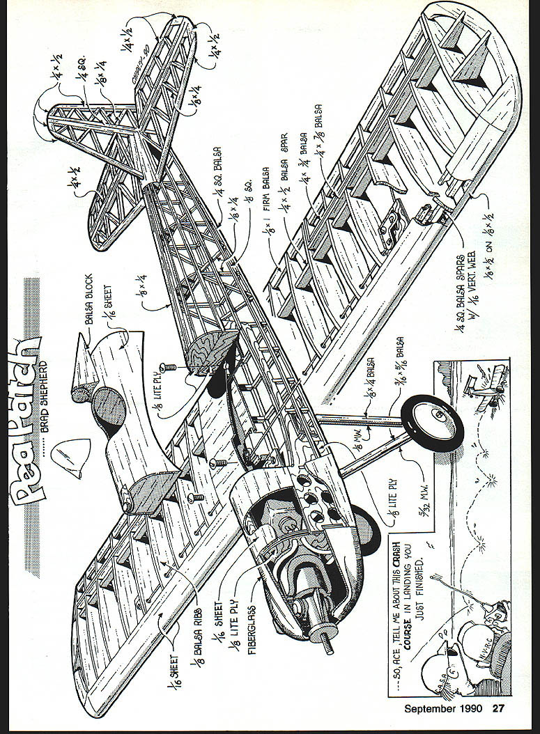
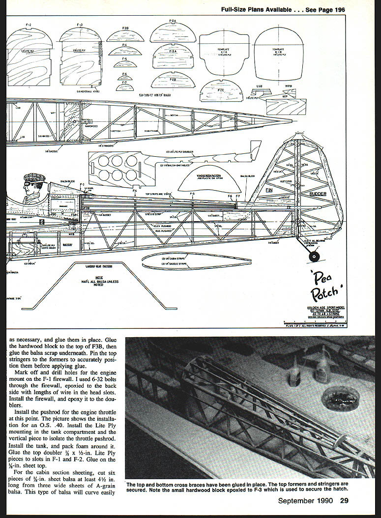
No continuing article text appears on this page — it contains only assembly/plan drawings, part labels and dimensional callouts (wing, fuselage and hardware details) for the Pea Patch.
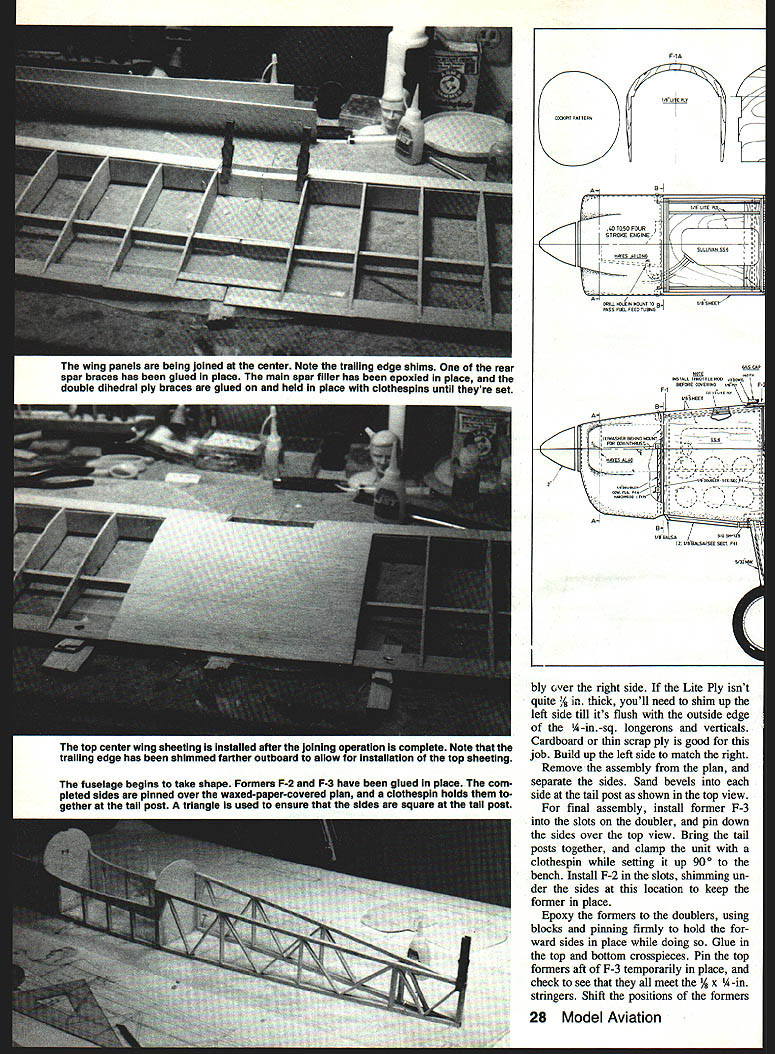
The wing panels are being joined at the center. Note the trailing edge shims. One of the rear spar braces has been glued in place. The main spar filler has been epoxied in place, and the double dihedral ply braces are glued on and held in place with clothespins until they're set.
The top center wing sheeting is installed after the joining operation is complete. Note that the trailing edge has been shimmed farther outboard to allow for installation of the top sheeting.
The fuselage begins to take shape. Formers F-2 and F-3 have been glued in place. The completed sides are pinned over the waxed-paper-covered plan, and a clothespin holds them together at the tail post. A triangle is used to ensure that the sides are square at the tail post.
Position left-side doubler assembly over the right side. If the Lite Ply isn't quite 1/8 in. thick, you'll need to shim up the left side till it's flush with the outside edge of the 1/4-in.-sq. longerons and verticals. Cardboard or thin scrap ply is good for this job. Build up the left side to match the right.
Remove the assembly from the plan, and separate the sides. Sand bevels into each side at the tail post as shown in the top view.
For final assembly, install former F-3 into the slots on the doubler, and pin down the sides over the top view. Bring the tail posts together, and clamp the unit with a clothespin while setting it up 90° to the bench. Install F-2 in the slots, shimming under the sides at this location to keep the former in place.
Epoxy the formers to the doublers, using blocks and pinning firmly to hold the forward sides in place while doing so. Glue in the top and bottom crosspieces. Pin the top formers aft of F-3 temporarily in place, and check to see that they all meet the 1/8 x 1/4-in. stringers. Shift the positions of the formers as necessary, and glue them in place. Glue the hardwood block to the top of F-3B, then glue the balsa scrap underneath. Pin the top stringers to the formers to accurately position them before applying glue.
Transcribed from original scans by AI. Minor OCR errors may remain.

