
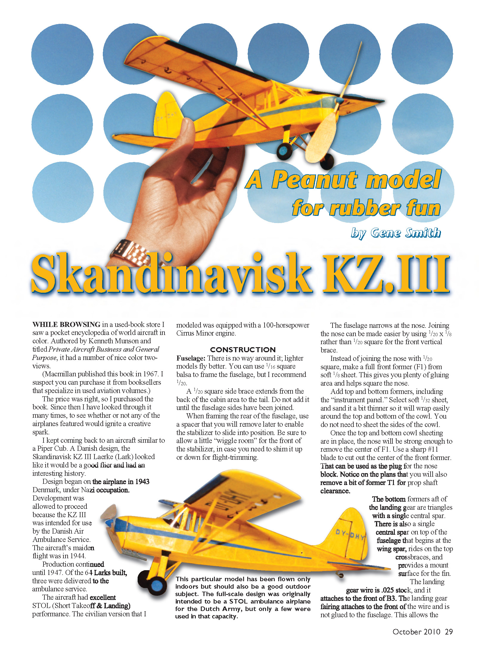
A Peanut model for rubber fun
by Gene Smith
Skandinavisk KZ.III
While browsing in a used-book store I saw a pocket encyclopedia of world aircraft in color. Authored by Kenneth Munson and titled Private, Business and General Aviation, it had a number of nice color two-views.
(Macmillan published this book in 1967. I suspect you can purchase it from booksellers that specialize in used aviation volumes.)
The price was right, so I purchased the book. Since then I have looked through it many times to see whether any of the airplanes featured would ignite a creative spark.
I kept coming back to an aircraft similar to a Piper Cub. A Danish design, the Skandinavisk KZ III Laerke (Lark) looked like it would be a good flier and had an interesting history.
Design began on the airplane in 1943 Denmark, under Nazi occupation. Development was allowed to proceed because the KZ III was intended for use by the Danish Air Ambulance Service. The aircraft’s maiden flight was in 1944.
Production continued until 1947. Of the 64 Larks built, three were delivered to the ambulance service.
The aircraft had excellent STOL (Short Takeoff & Landing) performance. The civilian version that I modeled was equipped with a 100-horsepower Cirrus Minor engine.
Construction
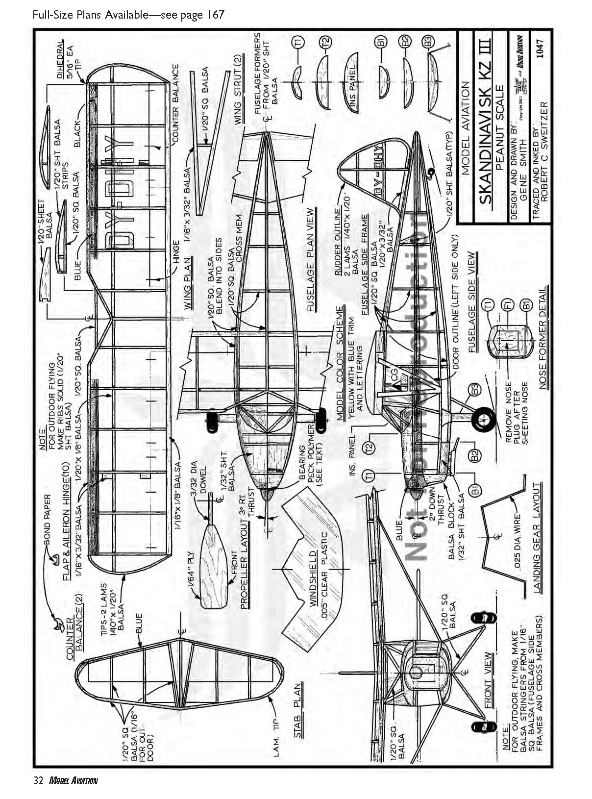
#### Fuselage There is no way around it: lighter models fly better. You can use 1/16-inch square balsa to frame the fuselage, but I recommend 1/20-inch square.
A 1/20-inch square side brace extends from the back of the cabin area to the tail. Do not add it until the fuselage sides have been joined.
When framing the rear of the fuselage, use a spacer that you will remove later to enable the stabilizer to slide into position. Be sure to allow a little “wiggle room” for the front of the stabilizer, in case you need to shim it up or down for flight trimming.
The fuselage narrows at the nose. Joining the nose can be made easier by using 1/20 x 1/8 rather than 1/20-inch square for the front vertical brace.
Instead of joining the nose with 1/20-inch square, make a full front former (F1) from soft 1/8-inch sheet. This gives you plenty of gluing area and helps square the nose.
Add top and bottom formers, including the “instrument panel.” Select soft 1/32-inch sheet, and sand it a bit thinner so it will wrap easily around the top and bottom of the cowl. You do not need to sheet the sides of the cowl.
Once the top and bottom cowl sheeting are in place, the nose will be strong enough to remove the center of F1. Use a sharp #11 blade to cut out the center of the front former. That can be used as the plug for the nose block. Notice on the plans that you will also remove a bit of former T1 for prop shaft clearance.
The bottom formers aft of the landing gear are triangles with a single central spar. There is also a single central spar on top of the fuselage that begins at the wing spar, rides on the top crossbraces, and provides a mount surface for the fin.
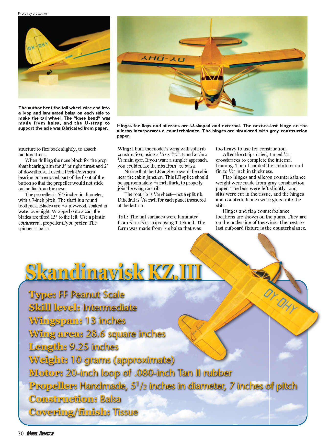
The landing gear wire is .025-inch stock, and it attaches to the front of B3. The landing gear fairing attaches to the front of the wire and is not glued to the fuselage. This allows the structure to flex back slightly to absorb landing shock.
When drilling the nose block for the prop shaft bearing, aim for 3° of right thrust and 2° of downthrust. I used a Peck-Polymers bearing but removed part of the front of the button so that the propeller would not stick out so far from the nose. The propeller is 5-1/2 inches in diameter, with a 7-inch pitch. The shaft is a round toothpick. Blades are 1/64-inch plywood, soaked in water overnight. Wrapped onto a can, the blades are tilted 15° to the left. Use a plastic commercial propeller if you prefer. The spinner is balsa.
Wing
I built the model’s wing with split-rib construction, using a 1/16 x 3/32-inch leading edge and a 1/20 x 1/8-inch main spar. If you want a simpler approach, you could make the ribs from 1/32-inch balsa.
Notice that the leading edge angles toward the cabin near the cabin junction. This LE splice should be approximately 1/8 inch thick to properly join the wing root rib.
The root rib is 1/20-inch sheet—not a split rib. Dihedral is 5/16 inch for each panel measured at the last rib.
Tail
The tail surfaces were laminated from 1/32 x 1/16-inch strips using Titebond. The form was made from 1/16-inch balsa that was too heavy to use for construction. After the strips dried, I used 1/20-inch crossbraces to complete the internal framing. Then I sanded the stabilizer and fin to 1/20 inch in thickness.
Flap hinges and aileron counterbalance weight were made from gray construction paper. The legs were left slightly long, slits were cut in the tissue, and the hinges and counterbalances were glued into the slits.
Hinge and flap-counterbalance locations are shown on the plans. They are on the underside of the wing. The next-to-last outboard fixture is the counterbalance.
Skandinavisk KZ.III
- Type: FF Peanut Scale
- Skill level: Intermediate
- Wingspan: 13 inches
- Wing area: 28.6 square inches
- Length: 9.25 inches
- Weight: 10 grams (approximate)
- Motor: 20-inch loop of .080-inch Tan II rubber
- Propeller: Handmade, 5-1/2 inches in diameter, 7-inch pitch
- Construction: Balsa
- Covering/finish: Tissue
Covering
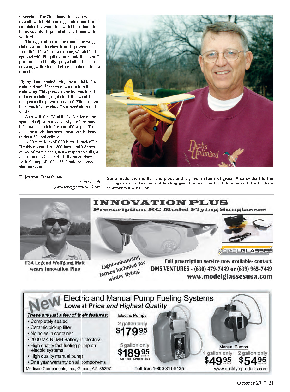
The Skandinavisk is yellow overall, with light-blue registration and trim. I simulated the wing slots with black domestic tissue cut into strips and attached them with white glue.
The registration numbers and blue wing, stabilizer, and fuselage trim strips were cut from light-blue Japanese tissue, which I had sprayed with Floquil to accentuate the color. I preshrunk and lightly sprayed all of the tissue covering with Floquil before I applied it to the model.
Flying
I anticipated flying the model to the right and built 1/16 inch of wash-in into the right wing. This proved to be too much and induced a stalling right climb that would dampen as the power decreased. Flights have been much better since I removed almost all wash-in.
Start with the CG at the back edge of the spar and adjust as needed. My airplane now balances 1/8 inch to the rear of the spar. To date, the model has been flown only indoors under a 38-foot ceiling.
A 20-inch loop of .080-inch-diameter Tan II rubber wound to 1,800 turns and 0.6 in-oz of torque has given a respectable flight of 1 minute, 42 seconds. If flying outdoors, a 16-inch loop of .100–.125-inch should be a good starting point.
Enjoy your Danish! MA
Gene Smith [email protected]
Full-size plans available — see page 167
Transcribed from original scans by AI. Minor OCR errors may remain.

