
PELIBAN - the Happy Bipe
Jack Headley
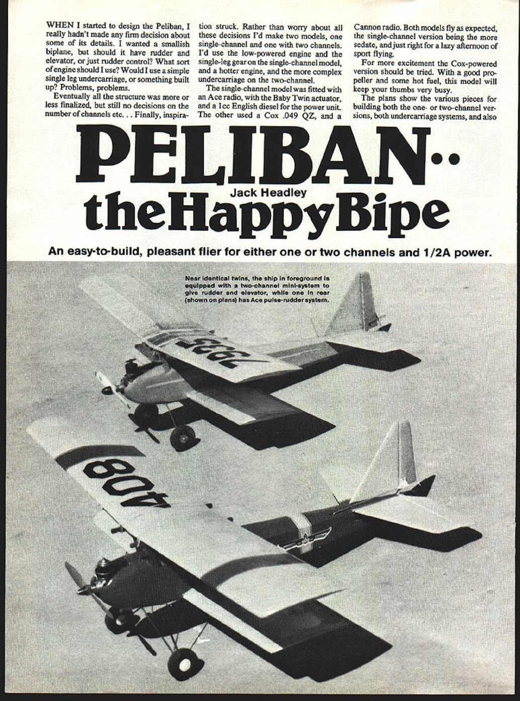
An easy-to-build, pleasant flier for either one or two channels and 1/2A power.
When I started to design the Peliban, I really hadn't made any firm decisions about some of its details. I wanted a smallish biplane, but should it have rudder and elevator, or just rudder control? What sort of engine should I use? Would I use a simple single-leg undercarriage, or something built up? Problems, problems.
Eventually all the structure was more or less finalized, but still no decisions on the number of channels... Finally, inspiration struck. Rather than worry about all these decisions I'd make two models, one single-channel and one with two channels. I'd use the low-powered engine and the single-leg gear on the single-channel model, and a hotter engine and the more complex undercarriage on the two-channel.
The single-channel model was fitted with an Ace radio, with the Baby Twin actuator, and a 1 cc English diesel for the power unit. The other used a Cox .049 QZ, and a Cannon radio. Both models fly as expected, the single-channel version being the more sedate, and just right for a lazy afternoon of sport flying.
For more excitement the Cox-powered version should be tried. With a good propeller and some hot fuel, this model will keep your thumbs very busy.
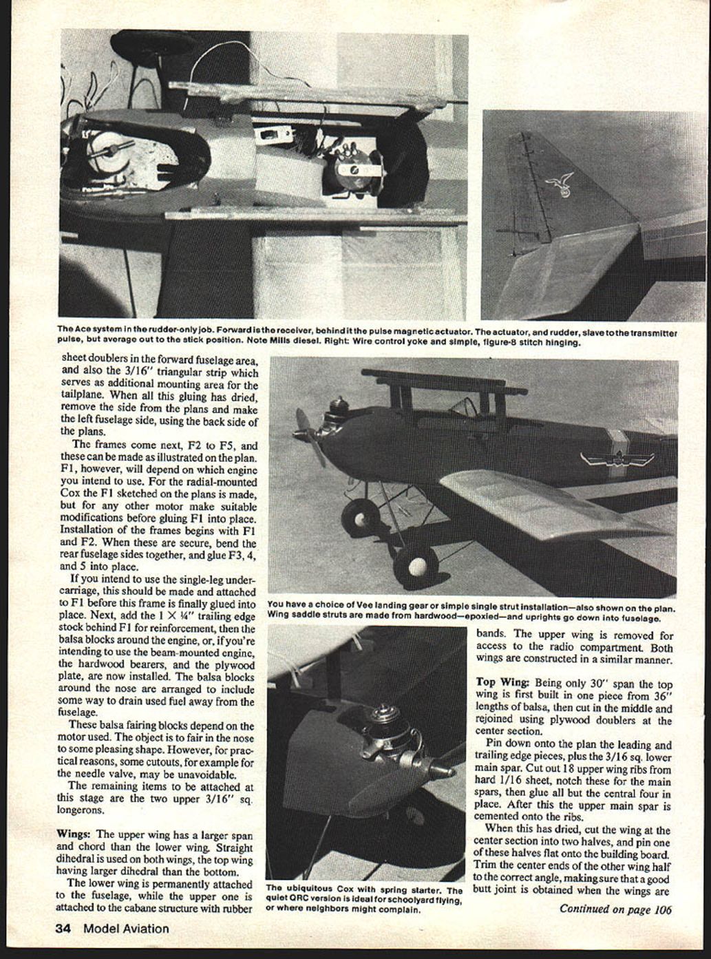
The plans show the various pieces for building both the one- or two-channel versions, both undercarriage systems, and also the mounting scheme for radial or beam-mounted engines. The wings and the basic fuselage are common.
On the two-channel model the rudder is made from thicker stock, for better compatibility with the hinges, whereas on the single-channel, a simple 1/8" sheet rudder is adequate, as this is sewn to the fin. In similar manner, the tailplanes of the two versions are different.
Naturally, it's better to use a higher-powered motor for the two-channel version, either the Cox QZR/C or a Medallion with a tank mount as suggested. For the lower-powered single-channel model either a mild Cox .049 or a diesel of about 1 cc capacity will be OK.
Fuselage
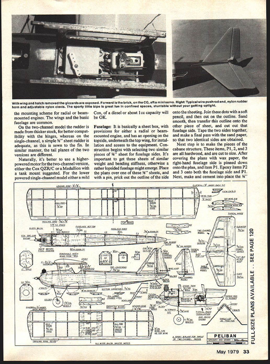
The fuselage is basically a sheet box, with provisions for either a radial or beam-mounted engine, and has an opening on the topside, underneath the top wing, for installation and access to the equipment. Construction begins with selecting two similar pieces of 1/8" sheet for fuselage sides. It's important to get these sheets of similar weight and bending stiffness, otherwise a rather lopsided fuselage might emerge.
Place the plans over one of these 1/8" sheets, and with a pin prick out the outline of the side onto the sheeting. Join these dots with a soft pencil, and then cut out on the outline. Sand smooth, then transfer this outline onto the other piece of sheet, and cut out that fuselage side. Tape the two sides together, and make a final pass with sandpaper so that two identical sides are obtained.
Next step is to make the pieces of the cabane structure. These items, P1, P2 and P3, are all hardwood and are cut to size. After covering the plans with wax paper, pin the right-hand fuselage side down onto the plan and position item P1. Epoxy items P2 and P3 onto both the fuselage side and P1. Next, make and cement into place the 1/8" bottom longerons.
Trailing-edge sheet doublers in the forward fuselage area and a 3/16" triangular strip serve as additional mounting area. After the tailplane gluing has dried, remove the side plans and make the left fuselage side using the back-side plans.
Frames come next. F2–F5 can be made as illustrated on the plan. F1, however, will depend on the engine you intend to use. For a radial-mounted Cox the F1 sketch on the plans is suitable; for other motors make suitable modifications before gluing F1 in place.
Installation of frames begins. Pin F1 and F2, secure and bend the rear fuselage sides together, and glue F3, F4 and F5 in place. If you intend to use the single-leg undercarriage it should be attached to F1 before the frame is finally glued in place. Next add the trailing-edge stock behind F1 and reinforcement balsa blocks around the engine. If you're intending to use a beam-mounted engine, hardwood bearers and a plywood plate are installed. Balsa blocks around the nose are arranged to include some way to drain used fuel away from the fuselage, and balsa fairing is added.
These balsa fairing blocks depend on the motor used. The object is to fair in the nose to some pleasing shape. However, for practical reasons, some cutouts (for example for the needle valve) may be unavoidable.
The remaining items to be attached at this stage are the two upper 3/16" sq. longerons.
Wings
The upper wing has a larger span and chord than the lower wing. Straight dihedral is used on both wings, the top wing having larger dihedral than the bottom. The lower wing is permanently attached to the fuselage, while the upper one is attached to the cabane structure with rubber bands. The upper wing is removed for access to the radio compartment. Both wings are constructed in a similar manner.
Top Wing
Being only 30" span the top wing is first built in one piece from 36" lengths of balsa, then cut in the middle and rejoined using plywood doublers at the center section.
Pin down onto the plan the leading and trailing edge pieces, plus the 3/16" sq. lower main spar. From hard 1/16" sheet cut out the upper wing ribs, notch these for the main spars, then glue all but the central four in place. After this the upper main spar is cemented onto the ribs.
When this has dried, cut the wing at the center section into two halves, and pin one of these halves flat onto the building board. Trim the center ends of the other wing half to the correct angle, making sure that a good butt joint is obtained when the wings are aligned at the correct dihedral angle. This angle is found by putting a wood block 2½" high under the tip of the free wing panel. Epoxy the spars together in the center section when a satisfactory joint has been made, then make and epoxy in place the 1/16" ply wing joiners W1 and W2. Add the remaining center section ribs. These will need a little trimming before they can be glued in place.
The wing tips, made from 3/4" sheet balsa, are the last items installed in the upper wing. After these have been attached, the wing is sanded to its final contour, and then prepared for covering.
Lower Wing
The lower wing is constructed in a single piece, exactly in the same way as the top wing. Pin down onto the building board the leading and trailing edge pieces, and also the lower main spar. From hard 1/16" sheet cut out ten lower wing ribs, and glue these in place. Cement the upper 3/16" sq. top main spar into these ribs, then, as before, cut the wing into two pieces on the center line and rejoin using the 1/16" ply wing joiners W3 and W4. Add the 3/8" sheet wing tips, then sand the wing to the airfoil shape shown on the plans. Construction of the lower wing will resume after the wing has been glued onto the fuselage.
Tail Plane
This begins with the assembly of the outline, composed of strips of 3/16" x 1/2" balsa. Pin these down onto the plan, then make the tailplane tips from scraps of 3/16" sheet, and glue in place. The required ribs are 3/16" sq. The center section of the tailplane is reinforced by two pieces of 3/16" sheet. The gap between them is provided for the fin, which is attached during the assembly.
For the single-channel version the tailplane is completed by adding two pieces of softish 3/16" sheet to represent the elevators. Glue in place, then thin down to about 1/16" at the trailing edge. The elevator for the two-channel version is cut from slightly harder 3/16" sheet. A good way of making two-piece elevators is first to make a single, full-length strip, which initially is notched in the center for the 3/16" dowel joiner. Epoxy this dowel in place, after which you can cut out the V-shaped notch at the center. This elevator is chamfered to about 1/16" thick at the trailing edge. Sand its leading edge to a full radius.
While you have the sanding block in hand, put a full radius on the tailplane outline.
Fin and Rudder
The fin is constructed in a similar way to the tailplane. An outline of 3/16" sheet is made, then the single 3/16" sq. rib is added. Since the fin extends under the tailplane, leave enough material to make the key piece. Sand a full radius on all the outside edges (except the bottom strip).
The rudder thickness depends on which system you're going to use. For single-channel the rudder is cut from a piece of 1/8" sheet, then rounded along the edges. For two-channel use 3/16" sheet, and chamfer in a similar manner to the elevator.
Assembly
The first items of concern are the fuselage and the lower wing. Cut slots in the fuselage for the wing leading edge and main spar only (the trailing edge rests on the bottom of the body), then check that these two items are correctly aligned before cementing the wing into place. Attach the tailplane, making sure alignment is OK in both top and front views, before gluing. Cement the fin into the slot provided.
If you use the two-legged undercarriage, it is now installed. The wire legs are attached to two 3/16" plywood plates with 1/8" bolts, plates being notched into fuselage sides. Check alignment before finally tightening the bolts, then epoxy the nuts in place.
Close in the bottom of the fuselage with 1/16" sheet, grain running crosswise. Follow this with lower fuselage frames, then add the two 3/16" sq. stringers.
Make two additional lower wing ribs from 3/16" sheet, trimmed to fit the wing root section, then glue in place in the wing and to the fuselage side. The resulting small wing bay is then covered with 1/32" sheet, top and bottom.
Radio Hatch
This hatch is shown on the plans. For a satisfactory fit, it is constructed on the model, thus truly conforming to contours. It is made from 1/8" sheet, and consists of two end frames, two sides, and a top. Build this as a complete box, then cut out the cockpit outline from the sides and the top, and add the windscreen. A small screw keeps the hatch in place.
Single-Channel Installation
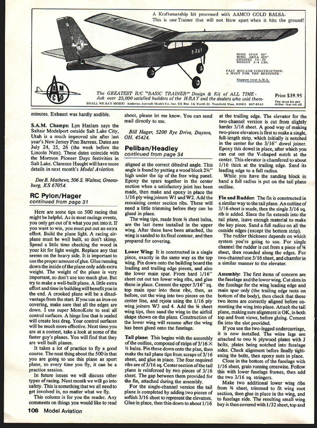
Shown on the plans is a typical single-channel system. Shown is the Ace, with Baby Twin actuator. If you use another system, make the necessary changes to the structure before construction has proceeded too far. The following instructions assume the Ace system.
Wrap the receiver and battery in foam rubber, and locate them as far forward as possible. A small scrap of frame made from 1/8" sheet helps to keep these items in position.
The actuator is bolted to a 1/16" plywood platform built over the wing structure in the fuselage. This platform is rigged at a slight angle so that the torque wire can run straight back to the rudder. A small nut epoxied under the ply platform is used for the actuator attachment. The torque wire is bent at right angles at its forward end, and this end is attached to the arm on the actuator with a scrap of plastic tubing. At the back end, the torque wire runs through the balsa block fairing, and a scrap of inner nyrod, epoxied inside this block, is used for a bearing.
The rudder actuator is made from a scrap of wire, with a small loop bent in its lower end. With the actuator installed, together with the torque wire, slip this loop over the rear end of the torque wire. Center the actuator, check that the small wire is vertical, then solder these two wires together.
The rudder actuator wire fits into a loop bolted to the rudder, and a small piece of plastic tube slipped over the wire here helps reduce interference with the radio.
Two-Channel Installation
I used a Cannon, and this fitted into the radio cavity quite easily. The receiver and servo were screwed to a 1/8" ply plate which was epoxied onto two hardwood rails attached to the fuselage side. The battery pack was located in front of, and underneath this ply plate, installed prior to fitting the receiver. Pushrods are made from 1/16" wire and 1/4" sq. balsa, connecting the servos.
This is a typical installation, and Ace servos, or the new small Kraft equipment, can be fitted. The emphasis is on placing the heavier pieces of the radio forward.
Covering
The single-channel version is covered with colored tissue, with a clear dope finish on the wings and color dope on the fuselage—this to keep the weight as low as possible, because the engine I intended to use isn't the powerhouse it used to be. For the two-channel model I used Solarfilm all over. A lightweight finish for the lower powered version is a good idea, so don't get too carried away with the trim scheme.
Flying
First, a ground-check is in order. Determine that the model balances at, or around, the CG location shown. Look for, and remove, any warps.
I found that the two-channel version will take off quite happily from the runway, but the single-channel model was better off if hand launched. Capability is not determined on the first flight, so perform several test flights making small revisions to the balance or the control throws to determine the optimum settings. From then on it should all be fun.
Transcribed from original scans by AI. Minor OCR errors may remain.

