
Perky Grande
BY DAVE ROBELEN
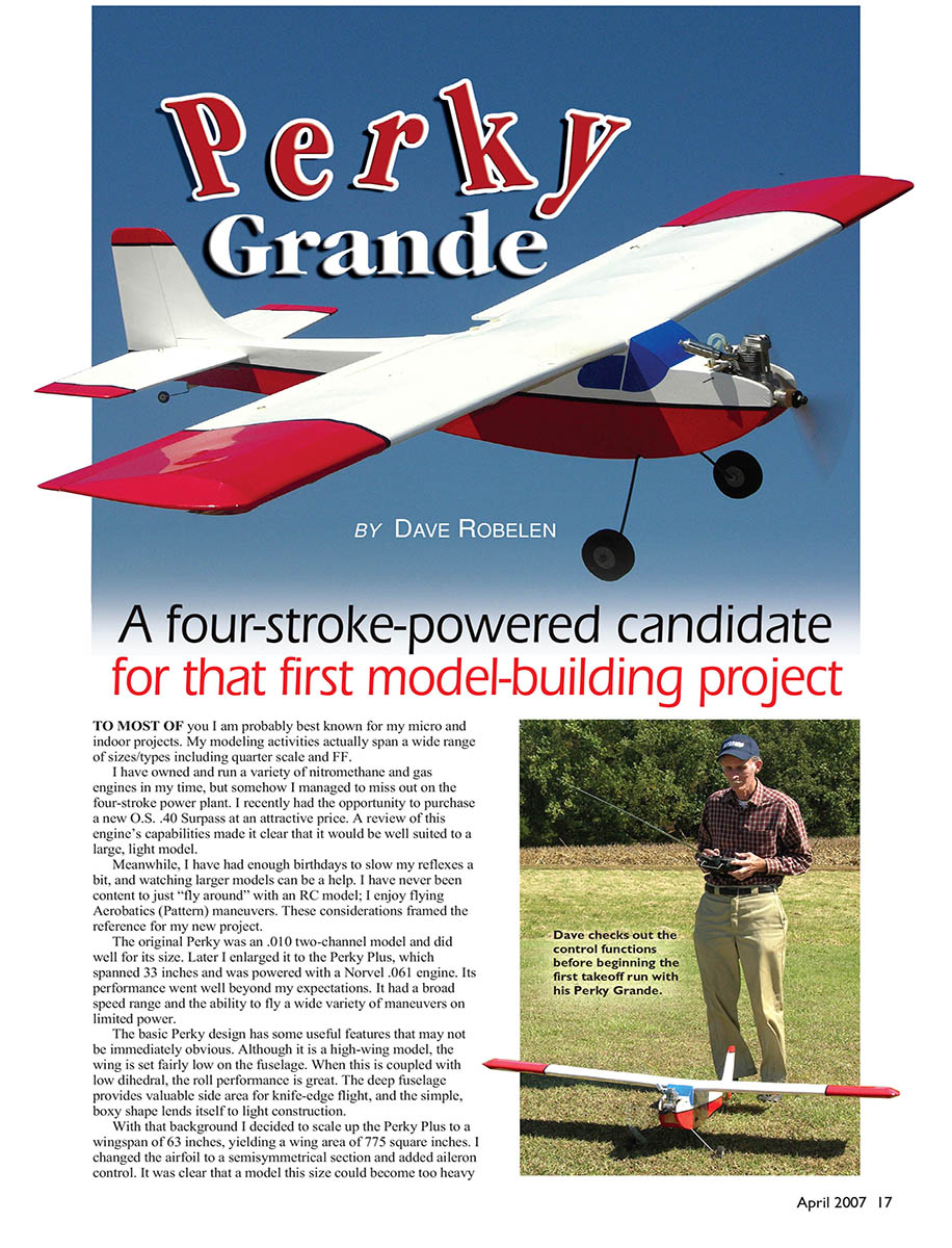
A four-stroke–powered candidate for that first model-building project
To most of you I am probably best known for my micro and indoor projects. My modeling activities actually span a wide range of sizes and types, including quarter scale and FF.
I have owned and run a variety of nitromethane and gas engines in my time, but somehow I managed to miss out on the four-stroke power plant. I recently had the opportunity to purchase a new O.S. .40 Surpass at an attractive price. A review of this engine's capabilities made it clear that it would be well suited to a large, light model.
Meanwhile, I have had enough birthdays to slow my reflexes a bit, and watching larger models can be a help. I have never been content to just "fly around" with an RC model; I enjoy flying aerobatics (Pattern) maneuvers. These considerations framed the reference for my new project.
The original Perky was an .010 two-channel model and did well for its size. Later I enlarged it to the Perky Plus, which spanned 33 inches and was powered with a Norvel .061 engine. Its performance went well beyond my expectations. It had a broad speed range and the ability to fly a wide variety of maneuvers on limited power.
The basic Perky design has some useful features that may not be immediately obvious. Although it is a high-wing model, the wing is set fairly low on the fuselage. When this is coupled with low dihedral, the roll performance is great. The deep fuselage provides valuable side area for knife-edge flight, and the simple, boxy shape lends itself to light construction.
With that background I decided to scale up the Perky Plus to a wingspan of 63 inches, yielding a wing area of about 775 square inches. I changed the airfoil to a semisymmetrical section and added aileron control. It was clear that a model this size could become too heavy for the .40 Surpass without serious weight control.
Therefore, I used 6- to 7-pound-per-cubic-foot balsa in the construction. An excellent source is www.lonestar-models.com. I used park-flyer–size servos for the ailerons and throttle and a 720 mAh, four-cell AAA NiMH battery (4.8 volts). Covered with MonoKote, the Perky Grande's total weight came out at 3.5 pounds without fuel. That seemed reasonable, especially with a wing loading of only 10.5 ounces per square foot. I installed a seven-channel receiver and set the model up to my Hitec RCD Optic 6 transmitter. This allowed the strip ailerons to be drooped in a flap configuration and still function as ailerons.
With a satisfactory range check completed, it was time to break in the new engine. The furnished literature sheet recommended a maximum of 10% nitromethane fuel, so that was what I started with. Starting and basic running went okay, but the needle valve seemed overly sensitive and the idle was too fast with a sloppy transition. I have been fortunate to have access to a master modeler—Forrest Mason—who really knows his engines. He pointed out that I should be using a minimum of 15% nitro and a composite propeller such as a Master Airscrew on a four-stroke engine. With these changes my engine settled down and ran like a charm.
With all the excuses used up it was time to go flying. Even on the takeoff roll it was becoming clear that the .40 Surpass would be more than ample power for the Perky Grande. As the flight progressed I worked my way through the Pattern maneuvers, delighting in the realistic speed and quiet sound during the flight.
Although the stalls were completely benign, I noted some yawing with aileron when flying at low speeds. I ended up mixing in 10% rudder with the aileron for a complete solution. An alternative is to add differential to the ailerons; that should accomplish the same thing but with a reduction in the maximum roll rate.
That deep fuselage really shone in knife-edge flight. Only approximately 30% rudder is needed to hold altitude. The stalls are gentle with the rudder and ailerons centered, and the generous controls provide positive snap rolls and spins, both positive and negative.
There was a mild surprise with the flaperon deployment. Instead of adding drag along with extra lift, in this case it appeared to add only an additional increment of lift without added drag. This brought the minimum speed down, allowing short landing rolls.
CONSTRUCTION
I benefit in my projects by rounding up the materials needed at the beginning. I used a variety of glues during construction: Elmer’s Carpenter’s Wood Glue, medium cyanoacrylate, thin cyanoacrylate, and 3M Super 77 spray contact cement.
Fresh, sharp cutting blades are a big help, as are a variety of sanding blocks. I have found the "Sand Blaster" brand of sandpaper to be especially useful on models; I found mine in the paint department at Wal-Mart.
Some sort of power saw—either a small band saw or a jigsaw—will be a big help. I also enjoyed using my Dremel circular saw for stripping wood.
As I mentioned, this model should be built with light balsa. The .40 four-stroke engine does not put excessive strain on the airframe, and the material sizes are adequate for the stresses. If you choose to go with more power, you are on your own. A .40–.46 two-stroke should be fine as an alternative to the .40 four-stroke.
Wing
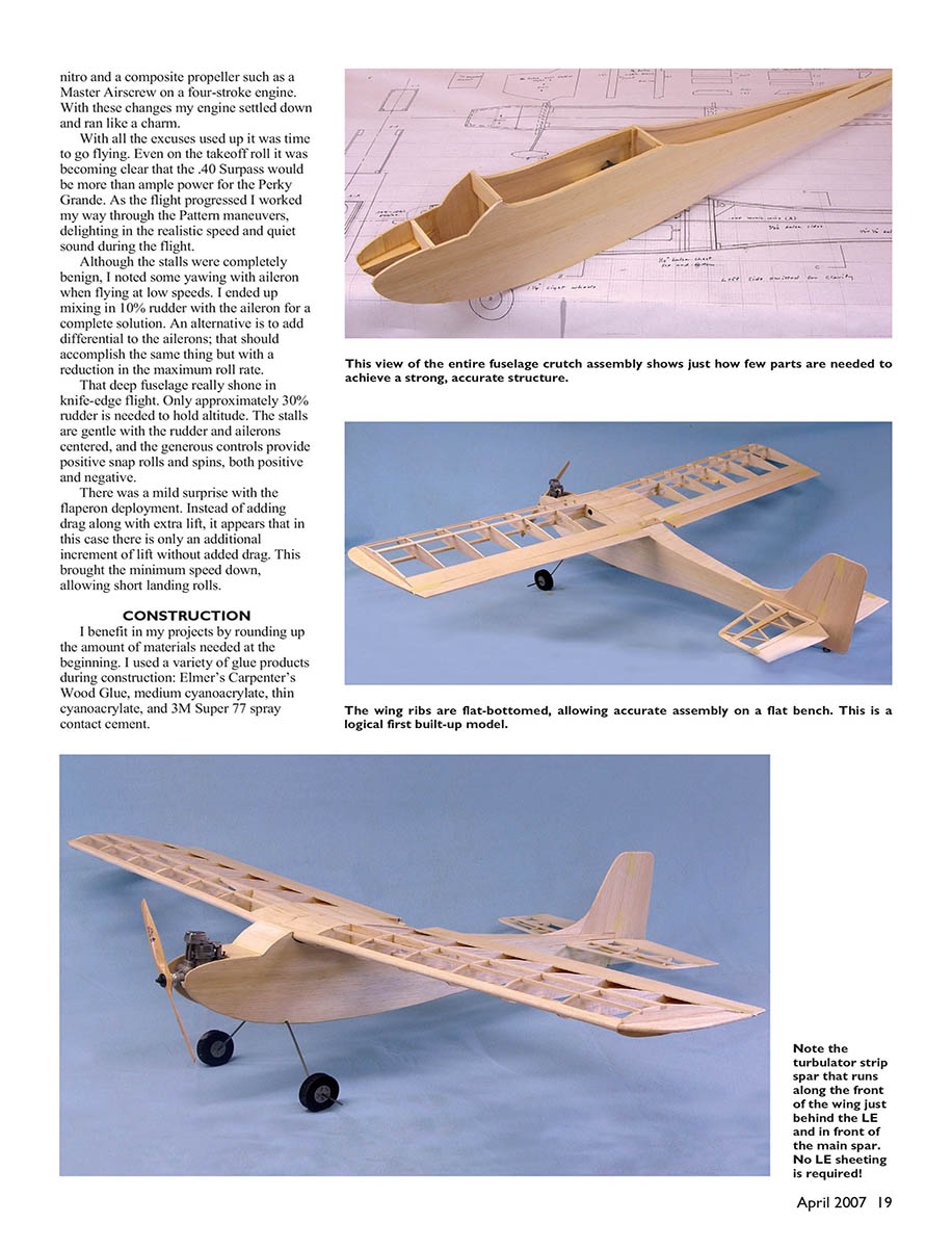
Construction should begin with the wing. I made a "kit" of parts before assembly so I could keep moving once I started pinning and clamping. The wing panels may be assembled on a flat surface.
For the 1/2 x 1/2-inch leading-edge strips I laminated two 1/4 x 1/2-inch strips with carpenter's glue; this trims and sands well and is plenty strong. One rib-cutting pattern is adequate for the various ribs. Except for the center ribs that are undercut for the sheeting, the only difference in the rest is the depth of the notches and holes for the servo cables.
This is also a good time to laminate the four spars. Be sure to taper the outer ends to avoid a stress concentration.
I started constructing my wing panels by clamping down the lower spar and trailing edge (TE). I added the center-section lower sheet between the spar and the TE, and then added all the ribs. Note the webbing in the center-section; this will be stronger with the grain vertical. Be sure to add the filler blocks for the center-section and the hinge locations at this stage.
Glue in the leading edge, upper spars, upper TE, and tip plate; one panel is finished. Repeat for the second panel. A minute amount of sanding will be needed on the root ribs to get a tight fit with the dihedral. At this point you can join the panels and add the center-section brace. Finish the sheeting to complete assembly.
Trim and sand the leading edge to the shape shown on the plan. A female template is a big help to check that both sides match. After a general sanding of glue lumps, set the wing aside until later.
Fuselage
Begin fuselage construction by splicing the side sheets for adequate depth. If you purchase 48-inch-long wood, no additional splicing is necessary; wood that is 36 inches long will require some length to be added at the tail.
When splicing long pieces, fit the edges carefully, trimming if necessary to get a tight seam without warping the sheet. If you splice length on the tail, use a scarf joint for adequate strength. My favorite technique for long splices is to hold the two sheets together and add masking-tape patches every few inches along the seam. Turn the sheets over, open the seam, and put a bead of carpenter’s glue along one edge. Press the assembly flat on the table with the masking-tape side down and wipe off the excess glue with a paper towel. Little sanding will be needed to obtain a smooth seam.
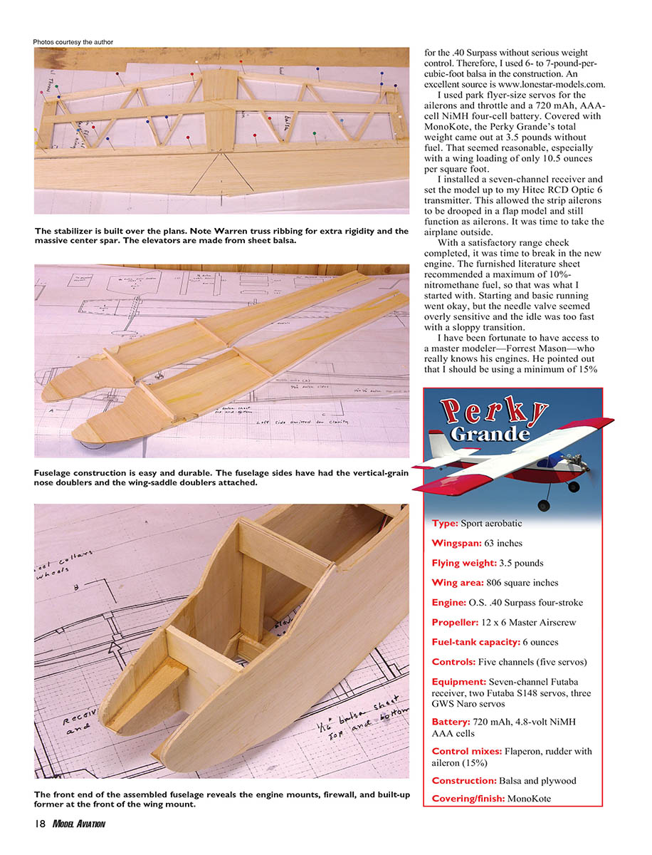
The nose doublers go on next. The 3M Super 77 spray cement can make a real mess of a floor, so lay down adequate newspaper. Mask off the part of the main side that is not glued and spray on a light coat of cement. Make a left and right side. You can join the doublers to the fuselage sides when the glue becomes tacky to the touch—rub the area firmly for a permanent bond. Add the rest of the edge stringers, landing-gear brace, and vertical cabin strips to complete two side assemblies. I chose this point in construction to cut the stabilizer opening in the two sides.
Join the two sides with the cabin braces first, making sure things are square. Pull the tail together and glue.
After I glued the F1 former in, I installed the engine mounts. I clamped a flat plate across the top of these in the engine area to ensure a flat mounting zone. I have found that medium cyanoacrylate gives a strong bond in this area and is less messy than epoxy.
Add the landing-gear block and wing hold-down plate, and plank the top and bottom with 3/32-inch balsa. Running the grain crosswise will result in more glue seams but is stronger and easier to install around the curves. Leave off the windshield piece at this point—you will need access to drill for the wing hold-down tube.
Fit the wing and trim as necessary for a tight fit. I used a rather long drill to reach through from the front to the wing center brace. Slide a piece of tubing in place and carefully square up the wing. Once satisfied, drill and tap for the 1/4-20 rear hold-down screws. Remove the wing and pull the tube out. I waited until after covering to finally glue the tube in. Now install the windshield sheet.
The stabilizer construction is basic. Assemble the 3/16 balsa frame and add the 1/8 balsa castrips and sheeting on the top and bottom. Refer to the side view for shaping the center section. Round the tips and leading edge, and leave the trailing edge square.
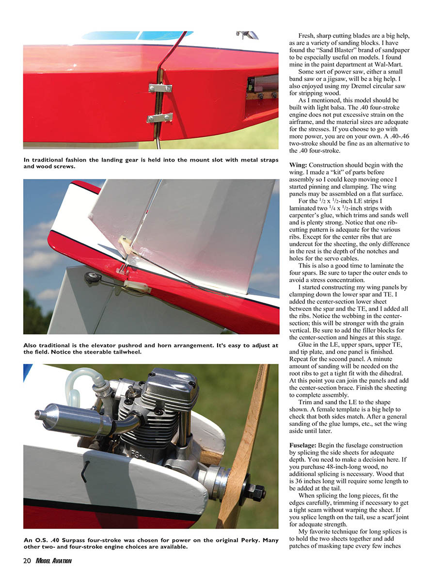
The ailerons may be sliced from 1/4-inch balsa stock. Round the tips and TE, and put a generous bevel on the LE. The elevators and vertical tail are cut from 3/16-inch stock. I left the elevators joined until I had installed the 3/32-inch-diameter piano-wire connector.
The landing gear is bent from 5/32-inch-diameter piano wire. I used a husky bench vise and hammer for this task. (Editor’s note: A better method is a heavy-duty K&S wire bender to ensure smooth bends with no chance of cracking the wire. If you use the vise-and-hammer method, be sure to grind a radius into one of the vise jaws and bend the gear around that radius.)
The tailwheel assembly uses a Goldberg bearing with a 1/16-inch-diameter wire strut and a 3/4-inch wheel. Install the landing gear after covering.
Covering: There are several good choices of material; I selected MonoKote for a combination of light weight, stiffness, and gloss.
Final assembly: Once I glued the wing hold-down tube in place, I mounted the wing to use as a reference for aligning the tail. Measure carefully and get the stabilizer parallel and square to the wing. The fin should be on the centerline and square to the stabilizer.
I used the “fuzzy” plastic cyanoacrylate hinges on all control surfaces. This is where the thin cyanoacrylate was put to use. Once the control surface was pressed into place and could move freely through the hinge line, I flowed a small amount of thin cyanoacrylate into the hinge slots. Give the glue time to dry and pull on the hinges to ensure they really are secure.
Mount the landing gear now, drilling for the vertical leg into the mounting blocks. I used a pair of aluminum straps to secure the legs. Mount the tailwheel using a hand grinder fitted with a parting wheel to cut a slot for the tab on the bearing. The assembly was glued in place with medium cyanoacrylate. I ironed four layers of MonoKote over the tiller arm to secure it to the rudder.
Mount the servos and control horns. I used a pair of Futaba S148 servos on the rudder and elevator and GWS Nano servos on the ailerons and throttle. My pushrods are made from stiff 1/4-inch square balsa with wire ends for the tail controls. The ailerons are connected with the threaded-end wire rods and snap links.
When it came time to mount the engine, I ran into a conflict with the carburetor linkage fitting and the F1 former. My mentor Forrest Mason suggested fitting a cap from a Sharpie pen in the firewall to provide clearance for the ball link I had chosen, and this worked to perfection.
I coated all exposed wood in the engine area with five-minute epoxy before mounting the engine. I chose clear polyurethane soaked into the fuel-tank compartment for protection.
Locate the receiver and battery so that the center of gravity (CG) is on the mark. (Do not attempt to fly the model tail-heavy.) Wrap these parts in soft foam for vibration protection.
At the field
Run the engine and check radio-range before leaving home to ensure the engine is well broken in and that the radio system has adequate range. A good starting point for control throws: 1/2 inch up and down on the ailerons, 3/4 inch up and down on the elevator, and at least 1 inch right and left for the rudder. These may be adjusted "to taste" after the initial flights.
If your Perky Grande is as light as mine, it will lift off easily with a rapid rate of climb. There is no reason to use full power except for maneuvers requiring vertical pull.
I wish you every pleasure with your project. I would love to see pictures from anyone who builds one of these models.
MA Dave Robelen [email protected]
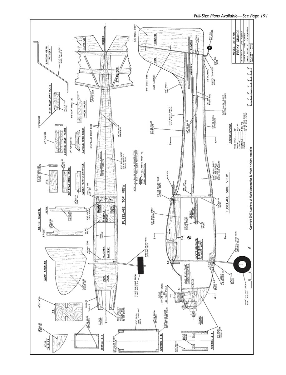
FUSELAGE TOP VIEW
- Cabin braces
- Front
- Rear
- Nose doubler
- Landing-gear block
- Landing-gear brace
- Motor mount
- Receiver battery
- Fuel tank
- Wing saddle
- Stabilizer location
- Elevator
- Rudder
- Tailwheel
- Fuselage stringers
- Fuse former locations
- Section C–C
- Section B–B
- Section A–A
FUSELAGE SIDE VIEW
- Engine mount / firewall
- Exhaust location
- Fuel-tank location
- Servo locations
- Control linkage exits
- Landing-gear attach point
- Wheel location
- Stabilizer and elevator hinge line
- Rudder hinge line
SPECIFICATIONS
- Type: Sport aerobatic
- Wingspan: 63 inches
- Flying weight: 3.5 pounds
- Wing area: 806 square inches
- Engine: O.S. .40 Surpass four-stroke
- Propeller: 12 x 6 Master Airscrew
- Fuel-tank capacity: 6 ounces
- Controls: Five channels (five servos)
- Equipment: Seven-channel Futaba receiver, two Futaba S148 servos, three GWS Nano servos
- Battery: 720 mAh, 4.8-volt NiMH AAA cells
- Control mixes: Flaperon; rudder with aileron (15%)
- Construction: Balsa and plywood
- Covering/finish: MonoKote
SECTIONS / DETAILS
- Nose doubler detail
- Landing-gear block detail
- Landing-gear brace detail
- Section views: A–A, B–B, C–C
(Note: The plan pages consist primarily of full-size plan views and labeled parts/details for the Perky Grande fuselage and associated sections.)
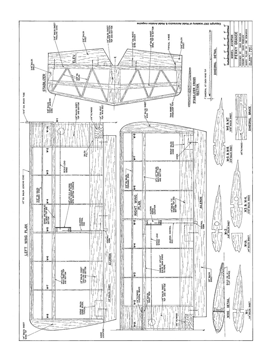
LEFT WING PLAN
- 1/8" x 3/16" balsa leading edge
- 3/32" balsa sheet top and bottom
- W-1
- W-2
- W-3
- W-4
- W-5
- W-6
- W-7
- W-8
- Aileron
- Aileron hinge location
- 1/8" sq. balsa spar
- Skeg layout
- Ail servo location
RIGHT WING PLAN
- 1/8" x 3/16" balsa leading edge
- 3/32" balsa sheet top and bottom
- W-1
- W-2
- W-3
- W-4
- W-5
- W-6
- W-7
- W-8
- Aileron
- Aileron hinge location
- 1/8" sq. balsa spar
- Skeg layout
- Ail servo location
STABILIZER
- Stab sheet top and bottom (3/32" balsa)
- Stabilizer rib/truss (Warren truss) for rigidity
- Stabilizer center spar
- Elevator
- Elevator hinge line
- Elevator made from sheet balsa
Stabilizer cross section
- Typical rib section
- 1/8" ply for shear web
Dihedral detail
- Dihedral brace
- 1/8" ply dihedral brace
Wing detail
- W-1A
- W-3 & W-4
- W-5 & W-6
- W-7 & W-8
- Rib shapes (full-size)
- Leading edge block
- Trailing edge sheet
DIHEDRAL BRACE
- 1/8" ply
- Brace locations shown on plan
TITLE BLOCK
- PERKY GRANDE
- Drawn by: (plans and copyright information shown)
- Copyright 2007 Academy of Model Aeronautics & Model Aviation magazine
(Note: The wing and stabilizer plan pages consist primarily of full-size plan views and labeled parts/details for the Perky Grande.)
Transcribed from original scans by AI. Minor OCR errors may remain.

