
Perky Plus
Dave Robelen
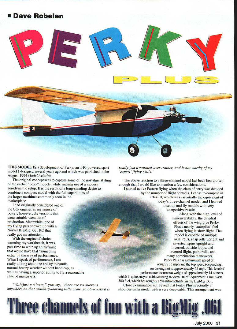
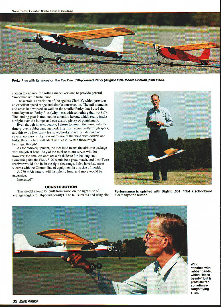
THIS MODEL IS a development of Perky, an .010-powered sport model I designed several years ago and which was published in the August 1994 Model Aviation.
The original concept was to capture some of the nostalgic styling of the earlier “boxy” models, while making use of a modern aerodynamic setup. It is the result of a long-standing desire to combine a compact model with the full capabilities of the larger machines commonly seen in the marketplace.
I had originally considered one of the Cox engines as my source of power; however, the versions that were suitable went out of production. Meanwhile, one of my flying pals showed up with a Norvel BigMig .061 RC that really got my attention.
With the engine of choice warming my workbench, it was past time to whip up an airframe that would have that “something extra” in the way of performance. When I speak of performance, I am really talking about the ability to handle normal breezy weather without handicap, as well as having a superior ability to fly a reasonable slate of maneuvers.
“Wait just a minute,” you say, “there are no ailerons anywhere on that ordinary-looking little crate, so obviously it is really just a warmed-over trainer, and is not worthy of my ‘expert’ flying skills.”
The above reaction to a three-channel model has been heard often enough that I would like to mention a few considerations.
I started active Pattern flying when the class of entry was decided by the number of flight controls. I chose to compete in Class II, which was essentially the equivalent of today’s three-channel model, and I learned to set up and fly models with very competitive results.
Along with the high level of maneuverability, the dihedral effects of the wing give Perky Plus a nearly “autopilot” feel when flying in slow flight. The model is capable of multiple axial rolls, snap rolls upright and inverted, spins upright and inverted, outside loops, inverted flight, point rolls, and many combination maneuvers.
Perky Plus has a minimum speed of roughly 15 mph and the top speed (depending on the engine) is approximately 65 mph. This level of performance assumes a weight of approximately 14 ounces, which is quite easy to achieve using modern “mini” equipment. I use K&B 500 fuel, which has roughly 15% nitromethane, in my BigMig .061.
Close examination will reveal that Perky Plus is actually a shoulder-wing model with a very deep cabin. This arrangement was chosen to enhance the rolling maneuvers and to provide general smoothness in turbulence.
The airfoil is a variation of the ageless Clark Y, which provides an excellent speed range and simple construction. The tail moments and areas had worked so well on the smaller Perky that I used the same layout on Perky Plus (why mess with something that works?). The landing gear is mounted in a torsion layout, which really tracks straight over the bumps and can absorb plenty of punishment.
Even though it lacks beauty, I chose to mount the wing with the time-proven rubber-band method. I fly from some pretty rough spots, and this extra flexibility has saved Perky Plus from damage on several occasions. If you want to mount the wing with dowels and bolts, the structure will adapt with ease. Watch those rough landings, though!
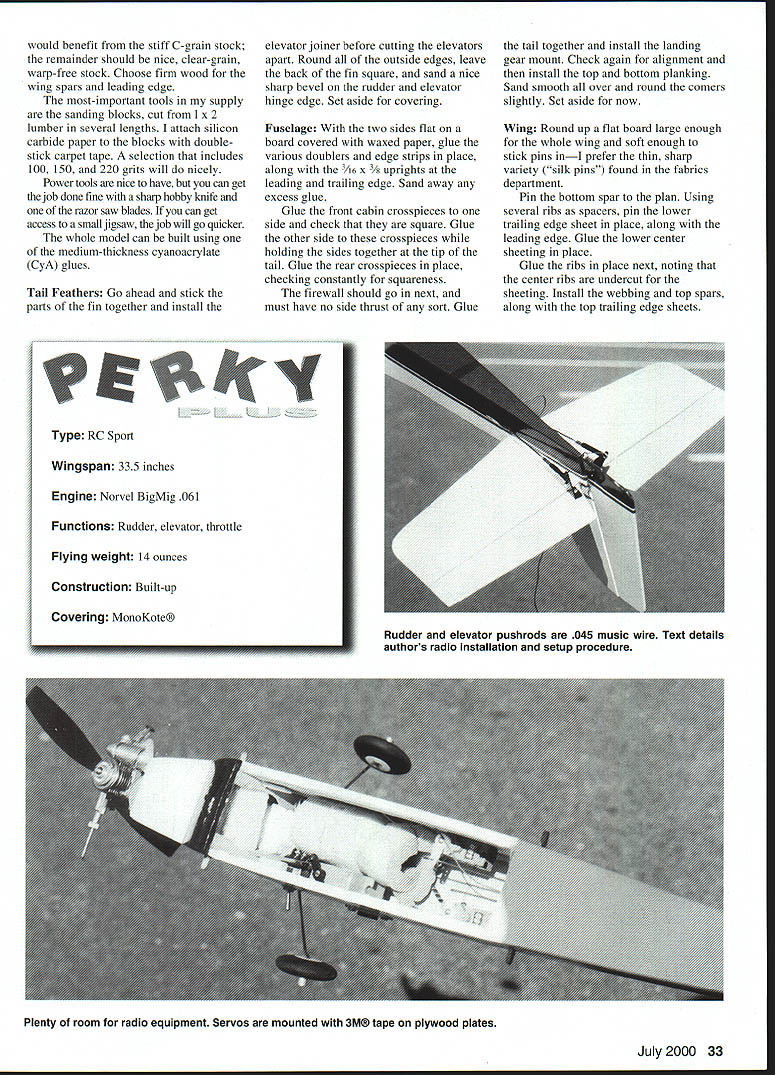
As for radio equipment, the idea is to match the airborne package with the job at hand. Any of the mini or micro servos will do; however, the smallest ones are a bit delicate for the long haul. Something like the FMA S-90 would be a great match, and their Tetra receiver would also be in the right size range. I also have had great success with the Cannon line of equipment in this size of model. A 270 mAh battery will last plenty long, and more would be excessive.
Interested?
CONSTRUCTION
This model should be built from wood on the light side of average (eight- to ten-pound density). The tail surfaces and wing ribs would benefit from the stiff C-grain stock; the remainder should be nice, clear-grain, warp-free stock. Choose firm wood for the wing spars and leading edge.
The most-important tools in my supply are the sanding blocks, cut from 1 x 2 lumber in several lengths. I attach silicon carbide paper to the blocks with double-stick carpet tape. A selection that includes 100, 150, and 220 grits will do nicely.
Power tools are nice to have, but you can get the job done fine with a sharp hobby knife and one of the razor saw blades. If you can get access to a small jigsaw, the job will go quicker.
The whole model can be built using one of the medium-thickness cyanoacrylate (CyA) glues.
Tail Feathers
- Glue the parts of the fin together and install the elevator joiner before cutting the elevators apart.
- Round all of the outside edges, leave the back of the fin square, and sand a nice sharp bevel on the rudder and elevator hinge edge.
- Set aside for covering.
Fuselage
- With the two sides flat on a board covered with waxed paper, glue the various doublers and edge strips in place, along with the 3/16 x 3/8 uprights at the leading and trailing edge. Sand away any excess glue.
- Glue the front cabin crosspieces to one side and check that they are square. Glue the other side to these crosspieces while holding the sides together at the tip of the tail.
- Glue the rear crosspieces in place, checking constantly for squareness.
- Install the firewall next; it must have no side thrust of any sort.
- Glue the tail together and install the landing gear mount. Check alignment and then install the top and bottom planking.
- Sand smooth all over and round the corners slightly. Set aside for now.
Wing
- Use a flat board large enough for the whole wing and soft enough to stick pins in—thin, sharp “silk pins” are preferred.
- Pin the bottom spar to the plan. Using several ribs as spacers, pin the lower trailing edge sheet in place, along with the leading edge. Glue the lower center sheeting in place.
- Glue the ribs in place next, noting that the center ribs are undercut for the sheeting. Install the webbing and top spars, along with the top trailing edge sheets.
- Finish planking the center and add the tip plates and filler pieces.
- When dry, remove from the board and inspect for poor glue joints. Fix as needed. Sand all of the joints smooth and shape the leading edge as shown.
- Cut the wing apart in the center and sand the center to the proper dihedral angle. Prop as needed and glue the two panels together with CyA.
- For insurance, glue a strip of fiberglass tape around the center with thin CyA. The result is very strong and will not blister or melt when covering is applied.
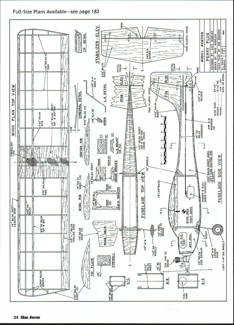
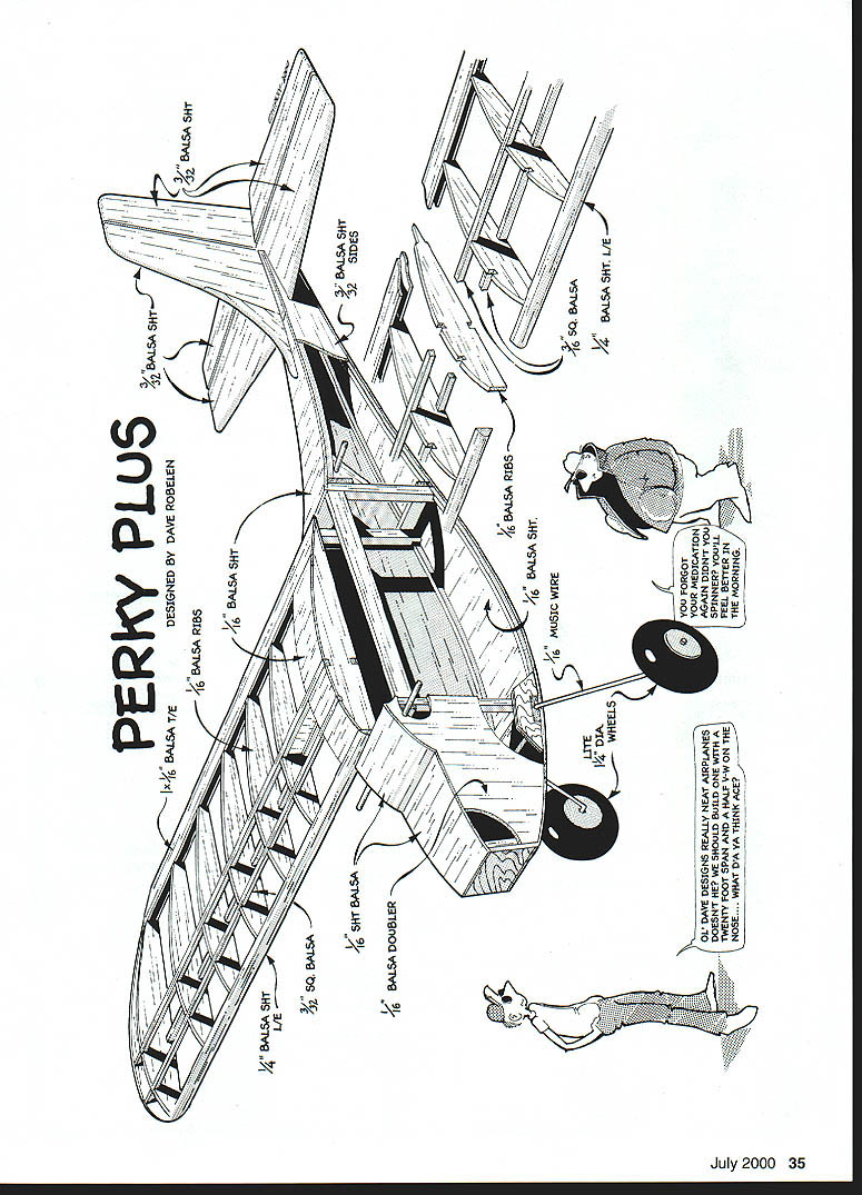
PERKY PLUS
Designed by Dave Robelen
- 1/16 BALSA RIBS
- 1/8 BALSA SHT
- 3/32 BALSA SHT
- 1/16 BALSA SHT
- 1/8 BALSA DOUBLER
- 1/16 SQ. BALSA
- 1/16 MUSIC WIRE
- 1/4 BALSA SHT. LE
- LITE 1/4" WHEELS
COVERING
I chose to cover Perky Plus with an iron-on plastic film. Since I had a supply of Super Monokote® on hand, this decision was simple. Any brand would likely do fine on the balsa sheeted parts; however, it is important that the wing be covered with one of the high-temperature (stiff) films to avoid the possibility of wing flutter.
Bond the covering completely to the wood surfaces.
ASSEMBLY
Hinging Elevator
- Hinge the elevator using thin plastic hinge material, cut into 1/8 x 1/2 strips.
- Slice into the exact center of the elevator and stabilizer edges at the locations shown.
- Slide the hinges halfway into the elevator, then slide this assembly into the slots in the stabilizer.
- Ensure free movement and set a 1/32 gap along the hingeline.
- Put one drop of thin CyA on the top and bottom of each hinge and let dry. Wiggle again to check freedom and tug on the hinges to check the bond.
- Fashion and install the thin plywood horns in the elevator and rudder, and set these parts aside.
Engine Mount and Gear
- I recommend one of the fiber-filled engine mounts (such as the Dave Brown Products version). Mount with small sheet-metal screws.
- Drill the hole for the throttle linkage housing (the skinny outer tube from a throttle cable set).
- Fit the wing dowels and glue securely, then mount the landing gear.
- I had good results using two loops of thin music wire pushed through the fuselage around the gear and twisted tight on the inside. Press the ends flat against the inside bottom when complete.
Alignment and Stabilizer
- Use a couple of medium rubber bands to strap the wing in position and check alignment in all directions.
- Leave the wing in place and slip the stabilizer in its slot. Recheck alignment carefully and, when satisfied, glue the stabilizer securely.
- Mark the fuselage centerline on the top rear and slice off a strip of covering where the fin will mount. Glue the fin in place and hinge the rudder in the same manner as the elevator.
- Mount the tail skid to the rudder as shown.
Fuel Tank
- One ounce is a suitable size for the tank. I made mine from a plastic bottle that once contained cleaner for soft contact lenses. The tank should be approximately one inch in diameter and two inches long.
- Use soft 3/32 brass tubing to make the feed and vent tubes, and fit these with medium silicone fuel line to make a fuel pick-up and a vent to the top of the tank.
- Usually it is possible to use the top of the bottle to contain these fittings.
- Locate the holes in the firewall accurately and pull some of that silicone tubing through, with the tank pushed up into the nose compartment. Mount your engine on the bracket and trim the tubing as needed.
- Wrap the battery in foam and slide it up under the fuel tank, using foam as needed to shove the tank all the way to the top of the compartment.
- Mount the wheels on the axles.
Pushrods, Receiver, and Servos
- The pushrods are solid lengths of .045 music wire. Chop off a couple of lengths and tape them to the tail cone in the approximate position.
- Place the receiver and servos in approximate positions and check the nominal balance without the wing. Shift parts around as needed and note their best position.
- I have successfully used servo mounting tape in these small projects. Glue a patch of thin plywood on the balsa in each servo location and use quality mounting tape (I prefer 3M®).
Mounting Rear Servos and Setting Rod Lengths
- Plug the radio equipment together and turn it on. Set the neutral position on each servo trim, then turn the batteries off (receiver first).
- Make one tight Z bend in the wire end and fish the unbent end through the guide hole toward the servo. Hook the bend in the control horn in the position shown and reach in the cabin and line up the other end with the servo arm.
- Mark the wire with the control surface in neutral and bend the servo end to mate with the desired hole. Do this twice to have a set of pushrods.
Throttle Setup
- Glue in a guide tube that comes back almost to the servo, and round up some .020 music wire.
- Since the holes in the servos and engine arm are too large, they need to be bushed. Good results have been had with small eyelets mashed in the holes, and slices from a plastic tube from a can of WD-40® pressed in the holes.
- Crank up the system and move the throttle servo from one extreme to the other. Mark these points on a scrap of business card and compare with the throttle arm throw. Choose a combination where the servo hole moves just a little less than the throttle (never more).
- Move the throttle lever to idle and set the trim in the middle of its range. Bend up the thin wire pushrod so that the carburetor arm is just touching the idle stop when the servo is at idle.
- (I removed the idle stop screw from my engine so I could set the idle with the transmitter trim. It also assures that my throttle servo will never be pulling against a solid stop and draining the battery.)
FIELD TIME
- Charge the batteries and complete any remaining work on the model.
- Check the Center of Gravity (CG) once more and inspect closely for any warps (remove if found).
- Do a decent range check and inspect the whole model again for forgotten details.
- Verify controls move the right way and that the engine runs.
Troubleshooting fuel/mixture: After considerable messing around, I found that the throttle moved on a screw thread to lean the mixture at idle by moving the needle valve closer to the main jet. With the muffler pressure connected, the needle valve was all but closing off the flow of fuel as it approached the idle setting.
My solution was to assemble a second needle valve and install it in the main feed line. This made the original needle valve the idle control, while the new needle controlled the top end. With these changes, the engine had a good top end and a nice slow idle for smooth settling, and it had the power for any maneuver. But the engine would die lean whenever I moved the throttle to idle.
The final change was to try a Cox glow head from a Black Widow, which fit right into the BigMig without any fuss at all. This plug runs just enough hotter that I then had the whole thing—idle, acceleration, and top end. This is not meant as criticism of a product, but rather my experience with an individual installation.
FLYING
Assuming your machine is reasonably aligned and balanced, pick a pretty day and let's get to it.
- Take off from a runway if you can; toss it if you must; but go for some altitude and throttle back to cruise. Were you surprised at the speed at full throttle? This is not a schoolyard flier.
- Assuming the controls trim out at neutral for straight-and-level flight, set the maximum throws.
- Set the throttle for medium cruise and snap the stick back in a U movement so that the elevator reaches maximum just before the rudder. If it snaps roll or does a barrel number, fine. If it does not snap cleanly, you need more up-elevator (to a maximum of 30°). If it still balks at the snap, it is probably nose-heavy and needs the CG moved back a bit.
- Once dialed in, spend time trying different propellers. My personal favorite is a Cox 7.5 shortened to 6.2 inches. This gives a good blend of speed, power, and fuel economy.
If you choose to build one of these little gems, I hope you have as much pleasure as I have had with my model. If you have any comments or questions, please write.
Dave Robelen Route 4, Box 369 Farmville, VA 23901
Transcribed from original scans by AI. Minor OCR errors may remain.

