
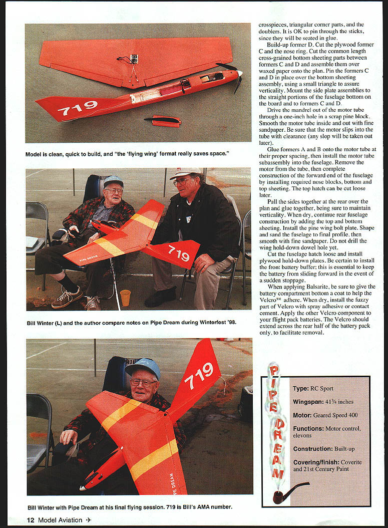
Pipe Dream: High-performance flying wing for Speed 400s
Bill Winter & John Hunton
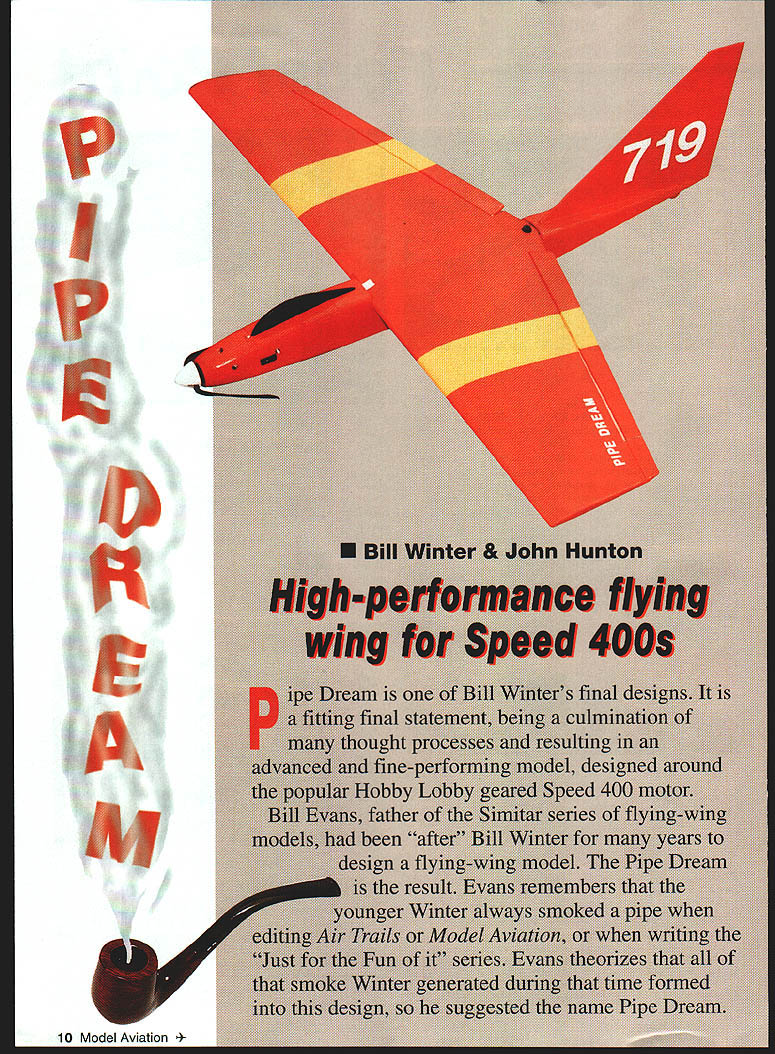
Pipe Dream is one of Bill Winter's final designs. It is a culmination of many thought processes and results in an advanced, fine-performing model designed around the popular Hobby Lobby geared Speed 400 motor.
Bill Evans, father of the Simitar series of flying-wing models, had long urged Bill Winter to design a flying wing. The Pipe Dream is the result. Evans remembers that Winter always smoked a pipe when editing Air Trails or Model Aviation or when writing the "Just for the Fun of It" series, and he suggested the name Pipe Dream.
Construction
Select light balsa (less than six-pound density). Some balsa suppliers will hand-pick wood for a surcharge or list guaranteed lightweight pieces; order extras to ensure good matches. Sheet balsa for wing sheeting must not be quarter-grain (which splits upon bending). It should curl easily along its length to match airfoil contours and avoid pulling free.
While you want light wood, avoid anything too "mushy." Use firmer strips for wing and fin leading edges (soft/medium ideal). Aileron and fin spars should be firmer wood. All blocks must be light. Follow the wood-size specs on the plans.
In addition to your usual adhesives, have a small quantity of yellow carpenter's (aliphatic resin) glue. Covering materials are by choice; suggested products include Coverite films, BalsaRite™, and 21st Century paints.
- Send wing root and tip airfoil profiles to a core cutter if you are using cores.
- Coat all raw balsa with BalsaRite to ensure good adhesion of the film; sand lightly before covering.
Materials and tools (suggested)
- Light balsa (< 6 lb density)
- Hard balsa for spars and leading/trailing edges
- 1/16" plywood for patterns and small parts
- 1/2" plywood for motor-tube construction (formed over mandrel)
- Yellow carpenter's (aliphatic) glue
- Epoxy and filler (microballoons)
- Coverite film, BalsaRite, 21st Century paints
- Masking tape, double-stick tape
- #11 blade, straightedge, sanding blocks, mandrel, drills and taps, servo rails
Fuselage
- Form the motor tube
- Form the motor tube from 1/2" plywood over waxed paper on a 1" mandrel.
- Wet the plywood and apply 50-50 thinned carpenter's glue on the mating surfaces with an acid brush.
- Wrap for two plies of thickness, then wrap with masking tape and set aside in a warm place to dry.
- When dry, smooth the motor tube inside and out with fine sandpaper. Be sure the motor slips into the tube; any clearance slop will be removed later.
- Side assemblies and longerons
- Cut out each side sheet and mark the location of all longerons, verticals, formers, and parts with a ball‑point pen.
- Pin each side sheet over the plan and install longerons, crosspieces, triangular corner gussets, and doublers. It is OK to pin through sticks since they will be seated while glue cures.
- Formers and bottom sheeting
- Build up former D. Cut plywood former C and the nose ring.
- Cut common-length, cross-grained bottom sheeting parts between formers C and D and assemble them over waxed paper onto the plan.
- Pin formers C and D in place over the bottom sheeting assembly using small triangles to assure verticality. Mount side-plate assemblies.
- Motor-tube subassembly
- Glue formers A and B (or B) onto the motor tube at the proper spacing, then install the motor-tube subassembly into the fuselage.
- Remove the motor from the tube and complete construction of the forward end of the fuselage by installing required nose blocks, bottom and top sheeting. The top hatch can be cut loose later.
- Rear fuselage and final shaping
- Pull the sides together over the rear of the plan and glue, maintaining verticality. When dry, add top and bottom sheeting and install the pine wing-bolt plate.
- Shape and sand the fuselage to final profile; smooth with fine sandpaper. Do not drill the wing hold-down dowel hole yet (drill after wing-fitting steps described below).
- Hatch, battery installation, and finish
- Cut the fuselage hatch loose and install plywood hold-down plates.
- Install a front battery buffer to prevent the battery sliding forward on sudden stoppage.
- Apply BalsaRite to the battery-compartment bottom to help Velcro adhere. When dry, install the fuzzy part of Velcro with spray adhesive or contact cement; apply the mating Velcro to the flight-pack batteries. Velcro should extend across the rear half of the battery pack to facilitate removal.
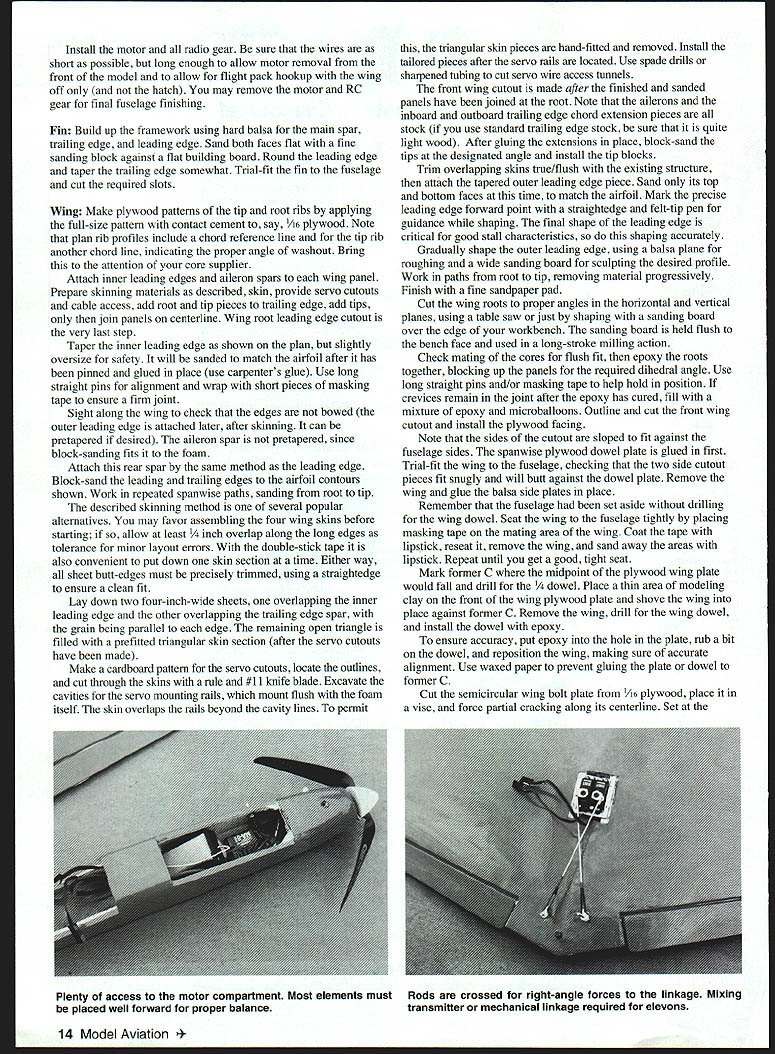
- Install motor and radio gear. Keep wiring as short as possible while allowing motor removal from the front. Allow flight-pack hookup with the wing off; the hatch may be removed to service the motor and RC gear.
- Final fuselage finishing completes this stage.
Fin
Build up the fin framework using hard balsa for the main spar, leading edge, and trailing edge. Sand both faces flat with a fine sanding block against a flat building board. Round the leading edge and taper the trailing edge somewhat. Trial-fit the fin on the fuselage and cut the required slots.
Wing
Patterns and cores
- Make plywood patterns for tip and root ribs by applying the full-size pattern with contact cement to 1/16" plywood.
- Note that the plan rib profiles include a chord reference line; the tip rib has another chord line indicating the proper angle for washout. Bring this to the attention of your core supplier if using foam cores.
Panel construction
- Attach inner leading edges and aileron spars to each wing panel.
- Prepare and fit skinning materials; the skin must allow servo cutouts and cable access.
- Add root and tip pieces to the trailing edge, add tips, then join panels at the centerline.
- The wing-root leading-edge cutout is the very last step.
- Taper the inner leading edge slightly oversize for safety; it will be sanded to match the airfoil after the panel has been pinned and glued in place. Use carpenter's glue. Use long straight pins for alignment and wrap short pieces of masking tape to ensure a firm joint.
- Sight along the wing and check that edges are not bowed. The outer leading edge, attached after skinning, can be pre-tapered if desired.
- Attach the rear spar by the same method as the leading edge. Block-sand the leading and trailing edges to the airfoil contours, working repeated spanwise sanding paths from root to tip.
Skinning method
Several alternatives exist. One common method:
- Assemble four wing skins (or work one section at a time with double-stick tape).
- Lay down two 4"‑wide sheets—one overlapping the inner leading edge and the other overlapping the trailing-edge spar—with the grain parallel to each edge.
- The remaining triangular area is filled with a prefitted triangular skin section after the servo cutouts have been made.
- Make a cardboard pattern for the servo cutouts, locate outlines, and cut through the skins with a #11 knife blade. Excavate cavities and mount servo rails flush. The skin overlap beyond cavity lines permits triangular skin pieces to be hand-fitted and removed for final fitting.
- Use spade drills or sharpened tubing to cut servo wire access tunnels.
Root join and dihedral
- Check mating of the cores for flush fit, then epoxy the roots together, blocking up the panels for the required dihedral angle. Use long straight pins and/or masking tape to hold position.
- If pinning after epoxy cure is necessary, fill with a mixture of epoxy and microballoons.
- Outline and cut the front wing cutout and install the plywood facing. Note the sides of the cutout are sloped to fit against the fuselage sides. Glue the semicircular plywood dowel plate in place first and trial-fit the wing to the fuselage.
- Seat the wing tightly: place masking tape on the mating area of the wing, coat the tape with lipstick, reseat the wing, remove it, and sand away the areas with lipstick. Repeat until you get a good, tight seat.
Wing dowel and hold-downs
- Mark former C where the midpoint of the plywood wing plate falls and drill for the wing dowel. Place a thin area of modeling clay on the front of the plywood plate and shove the wing into place against former C. Remove the wing, drill for the wing dowel, and install the dowel with epoxy.
- Cut the semicircular wing bolt plate from 1/16" plywood, place it in a vise, and force partial cracking along its centerline. Set at the required dihedral angle, then glue it to the top of the wing.
- With the wing in place, mark the center for the rear wing hold-down bolt and drill the hole through the wing into the hold-down blocks in the fuselage. Enlarge the holes as required to accept your wing hold-down hardware (final bolt typically 1/4" nylon). Tap the hold-down blocks as required for your chosen fastener. Apply 2"‑wide medium-weight fiberglass over the top and bottom of the wing center-section joint.
Control surfaces and hinges
- Trial-fit control horns to the ailerons and "dry run" the hinges for minimum gap between ailerons and aileron spar. Hinge slots depend on hinge type; Mylar™ hinges are light and strong if properly installed. Accurately mark hinge positions and cut slots with a #11 blade using a straight guide.
- Because the wing core is foam, use a cyanoacrylate compatible with foam. Install ailerons, servos, and linkages after covering.
Covering
- Coat all raw balsa with BalsaRite to ensure good adhesion of covering film. Sand lightly, then cover with film.
- Since this model can reach high altitudes, cover the bottom with a dark color and the top with a light color for good visual orientation.
- Install all radio equipment and pushrods. Balance the model exactly where shown on the plans; shift radio gear or add ballast if necessary—the flying wing configuration requires very accurate center-of-gravity (CG).
- Mark the battery location after balancing so it can be placed back in the same position every time. If you change battery types, balance again before flying.
- Check alignment of the fin with the fuselage and correct any wing warps. Normal elevon location is slightly up (see plans). Verify full elevon deflection for turns both ways with elevons full up and full down.
Flying
- For the first test flight, set the elevons slightly up as shown on the plans.
- With throttle at full power, launch Pipe Dream into the wind with a firm shove (not so hard as to dislodge the battery), preferably over tall grass.
- When climbing out, correct roll first, then pitch. Do not overcorrect; allow the model to gain speed, then initiate a gentle climb to a safe altitude and trim it out.
- Keep the model close and within good visual range until you become familiar with its performance and visual clues; then you can thermal-seek.
- The model glides best with the prop stopped and folded and with near full-up trim.
- To hand-launch: a firm push into the wind, keep low and straight until airspeed is established, then enter a gentle climb.
Landing, thermalling, and aerobatics
- To land: shut off power (prop stops and folds). If gliding with full-up trim, lower trim to gain some speed for stall safety near the ground. If it touches down fast the nose may pop up—stay with the controls and let speed bleed off until it settles in. With practice, Pipe Dream will skid smoothly to a stop at your feet.
- For basic thermal-seeking: trim the model at altitude to fly straight into the wind in small trim increments. Let it fly on its own; it will circle into lift. Minimize control inputs—each input increases drag and reduces efficiency. Use trim only to maintain a steady condition for lift-seeking.
- For aerobatics: reach altitude, shut down the motor, dive to gain speed (it will go faster than with the motor running), then perform loops or rolls.
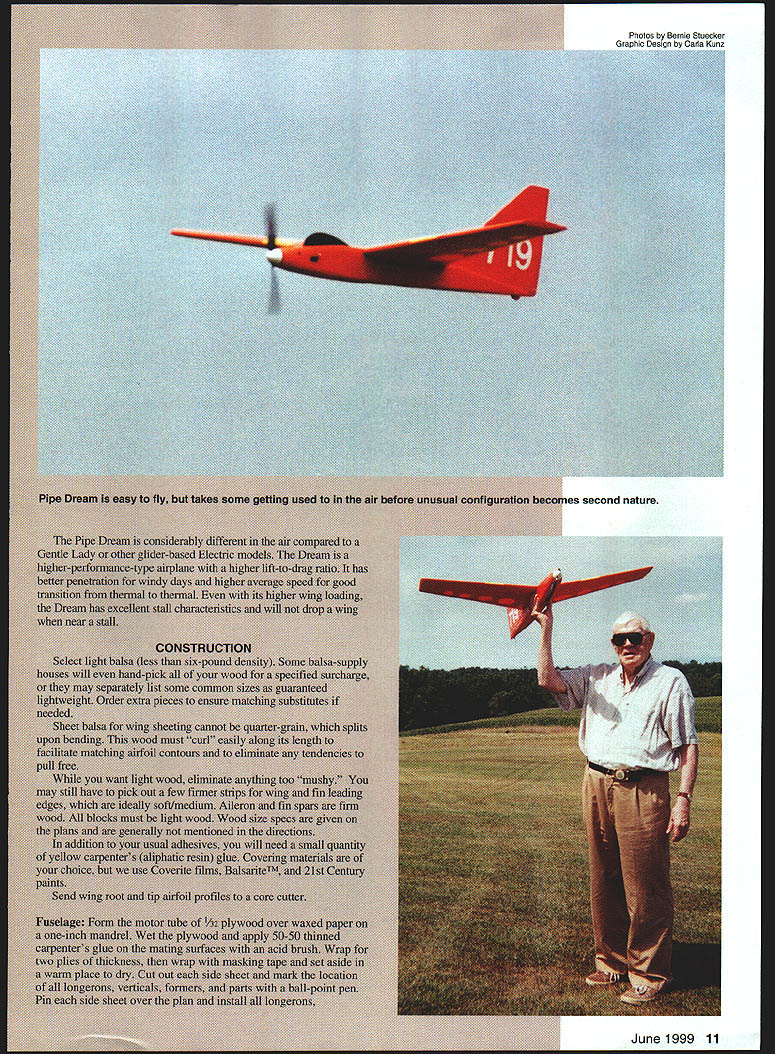
Pipe Dream is an efficient model with a wide range of capabilities and an excellent transition from glow to electric.
John Hunton 9154 Rixeyville Rd. Rixeyville, VA 22737
Transcribed from original scans by AI. Minor OCR errors may remain.

