
Piper Vagabond
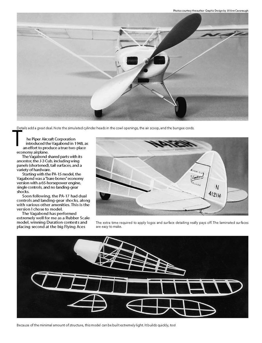
The Piper Aircraft Corporation introduced the Vagabond in 1948 as an effort to produce a true two-place economy airplane.
The Vagabond shared parts with its ancestor, the J-3 Cub, including shortened wing panels, tail surfaces, and a variety of hardware.
Starting with the PA-15 model, the Vagabond was a bare-bones economy version with a 65-horsepower engine, single controls, and no landing-gear shocks. Soon following, the PA-17 had dual controls and landing-gear shocks, along with various other amenities. This is the version I chose to model.
The Vagabond has performed extremely well for me as a Rubber Scale model, winning Duration contests and placing second at the big Flying Aces Club (FAC) Nationals at Geneseo, NY. My early versions were built from Walt Mooney Peanut plans. Although they flew extremely well, there was too much compromise in the design for it to be successful in a true Scale event.
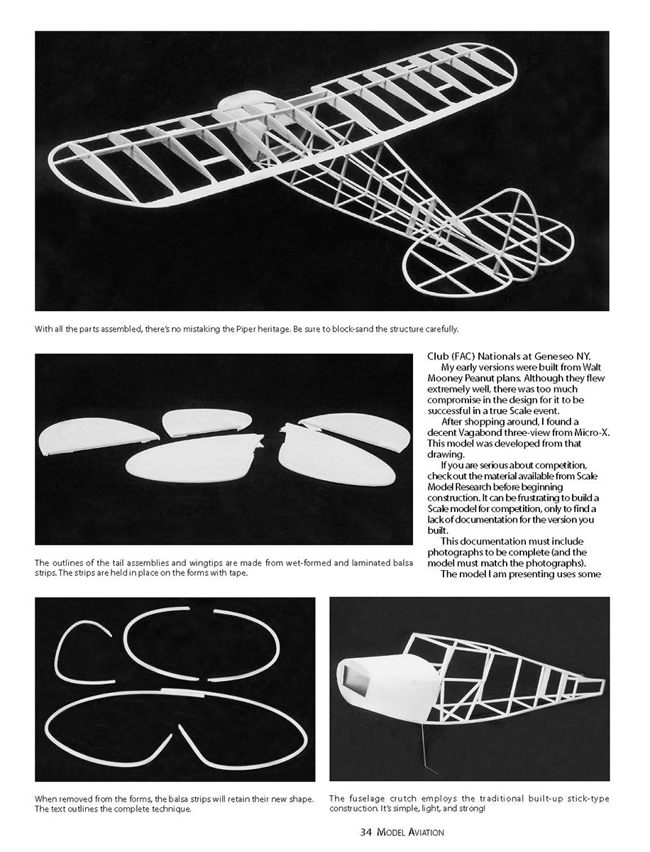
After shopping around, I found a decent Vagabond three-view from Micro-X. This model was developed from that drawing. If you are serious about competition, check out the material available from Scale Model Research before beginning construction. It can be frustrating to build a Scale model for competition only to find a lack of documentation for the version you built. This documentation must include photographs to be complete (and the model must match the photographs).
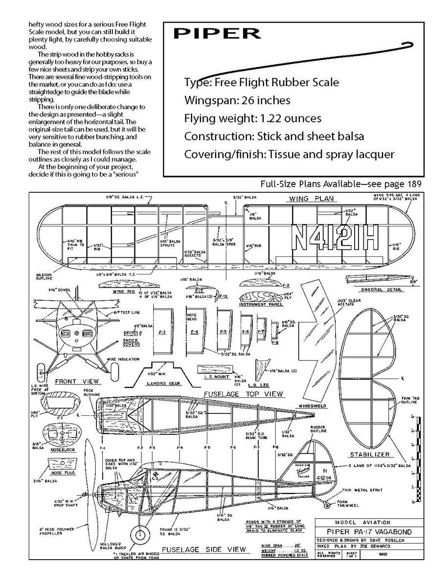
The model I am presenting uses some hefty wood sizes for a serious Free Flight Scale model, but you can still build it plenty light by carefully choosing suitable wood. The strip wood in the hobby racks is generally too heavy for our purposes, so buy a few nice sheets and strip your own sticks. There are several fine wood‑stripping tools on the market, or you can do as I do: use a straightedge to guide the blade while stripping.
There is only one deliberate change to the design as presented—a slight enlargement of the horizontal tail. The original‑size tail can be used, but it will be very sensitive to rubber bunching and balance in general. The rest of this model follows the scale outlines as closely as I could manage.
At the beginning of your project, decide if this is going to be a "serious" Rubber Scale entry or just a very enjoyable sportflying model. This decision affects the way you detail your model and things such as the choice of wheels. A proper Rubber Scale entry requires that you fashion foam wheels matching the aircraft version you have, and add all those little point-getting details around the nose and cowling.
Whichever way you choose to use your model, please build the Vagabond as light as you can, for nice, gentle flight qualities. It is a mistake to reinforce a model against the possibility of a crash, because it almost assures one.
Since there are no deliberate warps necessary, make every effort to keep your model straight and true. If you are new to laminated outlines, this will be good exercise.
Choose a flat and clear work area, with good lighting and minimum distractions. I do most of my projects on an old conference table, with a fluorescent shop light over it. Take your time and enjoy the construction, making a "project" of each small part. This way, you will do yourself proud as it all comes together.
CONSTRUCTION
Begin with the laminated parts as a warmup.
Strip enough 3/32-inch-wide lengths from a light, flexible sheet of 1/32-inch A- or A-B-grain balsa to construct all the laminated parts. The A- or A-B-grain balsa has long, straight fibers and will mold, or form, easily. Do not use C-grain balsa for these operations; it will break or crack when it's bent around the forms. It is easy to distinguish A- and A-B-grain from C-grain, which will have a short grain that resembles fish scales.
There is a variety of choices for form materials. I usually select the crummiest balsa I can find in the hobby shop rack, then try to convince the dealer to discount it to clear it out of stock! Cut the form outlines to conform to the inside curve of the parts, and make the forms slightly longer than the finished parts. Rub a bar of soap around the edges of the forms, and they are ready. (The soap prevents the glued strips from sticking to the forms.)
Things can get busy during the forming process, so pick a time with the least chance of distractions. Get a pot of hot water with a capful of ammonia mixed in for soaking the strips. This combination makes the wood fibers more pliable.
Use masking tape to hold the laminated strips to the forms. Tear off a bunch of short tape pieces and lightly stick them where you can reach them easily when you are ready for them. Put the balsa strips in the pot so that they are covered with the hot water and ammonia solution. You will probably need a couple of light weights to keep the wood submerged. If you are working in the kitchen, it is best to do all this alone and clean up carefully when you are finished.
I use Elmer's white glue for the following task. Start with a wingtip, and pull one strip from the ammonia/water solution, quickly coating it with a very light bead of glue on one side. Keep moving, and pull three more strips out until you have a sandwich of four strips with a bead of glue between each one. Starting at one end, place the strips against the form and wrap masking tape tightly around the end. Squeeze the strips together and pull them around the form, keeping tension as you go. Use a piece of tape to fasten that end. Finish the remaining edges. Put the wet parts in the oven on a low setting and give them roughly an hour to dry.
This is a good time to clean the kitchen and scrub that pot well. When the parts are dry, pull them out of the oven and carefully peel the tape away. If you did the job right with the soap, the strips will "pop" free from the forms. Set the laminated parts aside, and make the rest of the wing parts. Trim the trailing edge to shape, sand it smooth, then check it carefully for warps or bows.
Strip a leading edge and a spar, and cut the ribs out using a template. Stack the ribs and push a couple of pins through the pile. Sand the whole stack smooth and to the same shape. The balsa caps go on two tip ribs and the two center ribs. The remainder of the ribs are cut from 1/32-inch balsa stock.
Smooth the plan down over a flat board that can take pins easily and cover it with waxed paper. Pin the trailing edge in place and, using several ribs as spacers, pin the leading edge down. Fit the rest of the ribs in place and glue each one with a spot of gap-filling cyanoacrylate (CyA) glue. Affix the gussets in place with a minimal amount of CyA, then trim and fit the laminated tip bows. Lift the tip bows to the angle shown on the plan, then glue them in place.
When the glue is dry, cut almost through the trailing edge from the top and lift the wing panels to the proper dihedral angle. Support them with scrap balsa pieces, pinning them securely in place while you trim and glue the spar to the ribs. Install the vertical brace between the two center ribs. Glue the gussets in the leading-edge corners, and you've done it.
When all is dry, lift the wing off the board and block-sand it carefully. Reglue anything that looks suspicious. Set the wing aside for now.
Tail
Try to find stiffer-than-average wood for the tail strip-wood, and cut and fit things together, pinning as needed. Use just enough adhesive to hold things without forming glue puddles or fillets. Glue is heavy, and an excess amount will not make the joint any stronger. Block-sand the tail surfaces smooth when dry, and round the edges neatly. You can then sand them aside with the wing.
Fuselage
Strip some light, flexible stock for the basic frame. Assemble two sides on the dark lines depicted on the plan, noting the wider balsa strips at the front of the cabin and rubber anchor post. When all is dry, block-sand both surfaces of each fuselage side smooth. Look at the cross-sections and note that two vertical stations are cracked and reglued with a slight bow. Please make only one right and one left!
Assembly of the sides starts with the two top crosspieces between the wing, which are the same length. It will be a big help if you pin things down over the top view for this step. Install a temporary crosspiece at the landing-gear station. Check that everything is square, and cut partway through the longerons where they bend to meet at the tail. They should form a straight line from the cut to the tail post.
Cut and fit the rest of the crosspieces from the wing aft. Cut the two nose crosspieces and pull the sides in to contact them. Crack the longerons if needed to get a straight line from the cabin to the nose. Glue these crosspieces in place, then fit the nose bulkheads, gluing as you go. Install the bulkhead at the instrument-panel station.
Scout out some flexible 1/32-inch balsa sheet and cover the top of the nose. (You may need to join two pieces of 1/32-inch balsa sheet for this operation.) This is a good place to use some of that nice, slow-drying Elmer's white glue. Masking tape will also be a big help here. Work slowly and cover the areas of the nose indicated on the plan.
Once the glue has dried, trim and sand the sheeting to a perfect fit. Install the 1/64-inch plywood nose bulkhead. Find a soft balsa block for the bottom nose piece; rough-shape the outside and the angle needed for it to fit properly against the nose bulkhead. Gouge the balsa from the inside of this block until you achieve a 3/8-inch wall section. Glue the block in place. When the glue is dry, sand the entire nose section to a smooth contour.
Bend up the 1/32-inch-diameter wire landing gear and sandwich it between layers of 1/16-inch balsa. Glue this assembly together with gap-filling CyA and squeeze firmly enough that the wire mashes into the wood until the two pieces meet. Pop out the temporary crosspiece and glue the landing-gear assembly in place.
You have some choices on the nose block. If you are going to fly the Vagabond for fun, you might skip the recessed cylinder openings and paint these areas flat black. However, if this is going to be a contest model, spend some time on this important area; carefully match the nose to your research photographs and three-views.
Glue the 3/16-inch balsa nose plug onto the nose block and drill for the nose bearing. Fit the nose block to the fuselage and carefully blend things with the sanding block. Check the plan for position and install the 1/16-inch balsa stringers.
Make the landing-gear legs, wing struts, simulated engine air scoop, and any other details you will cover with tissue.
Covering/Finish
I shouldn't tell you much about covering your model with tissue, since I have more problems than any two people I know! Check out some good articles on the subject, and come back. However, I will mention materials that have worked well for me.
Esaki tissue does a great job and has good wet strength. I adhere it to the airframe with Elmer's School Glue (gel stick) from the stationery department. It stays sticky a while, and only a thin film is needed. Rubbing alcohol misted on with a nasal-sprayer is adequate for tightening the tissue. A couple of thin coats of Krylon Crystal Clear spray lacquer provides a decent finish.
Pin the wings and tail down whenever they are drying to prevent warping. Acetone brushed through tissue trim will hold it in place nicely. A fine-tip Sharpie pen against a straightedge is ideal for adding control surface outlines, door openings, etc.
Assembly
Make up the propeller shaft with some washers and all the necessary bends, and make sure things spin freely. Cut and install the aluminum-tube rear rubber hanger.
Install the wing now. I use slower-drying wood glue here to allow some working and alignment time. Check from all angles to make sure that things are perfectly aligned before gluing. Let this assembly dry thoroughly before proceeding.
Install the instrument panel and the two cabin braces. Before mounting the windshield, I use a felt-tip marker to color all exposed wood to match the tissue. Make a windshield template from notebook paper. Hold the template in place and mark and trim until it fits perfectly. When you are satisfied with the fit, transfer the shape to sheet acetate and cut it out carefully. (I found my acetate at a mall craft store.)
The gel school glue is excellent for attaching the windshield. Use very little glue and many pins, and let it dry thoroughly. Mount the tail with small spots of wood glue, and check the alignment all around. Adhere the vertical tail with glue at the tail post only, to allow for adjustment.
Finish the landing gear, making sure the wire legs can flex backward without breaking anything. Install the wing struts and tail-wheel assembly, and you are on the home stretch. If you are thinking about competition, now is the time to add rigging wires, control cables, and all those neat nose details.
Examine the whole model and remove any warps or other problems that might have crept in. Make the rubber motor from four 30-inch-long strands of 1/8-inch Tan II rubber, and tension it so it does not flop around. Check the balance against the plan and add weight as necessary to correct.
Flying
Hand-gliding a model like this is useless and might even break it! Start with just enough winds in the rubber to have a powered glide. I like to see the Vagabond go basically straight ahead, with no stall and definitely no diving. Add more winds, and try again.
Look for a very wide right circle when the model has enough power to climb. Use a combination of thrust adjustments and rudder turn to achieve this flight.
Transcribed from original scans by AI. Minor OCR errors may remain.

