
The Pits and the Pendulum
By Bob Haight
The use of pendulums for control of rudder, ailerons, or elevators — and in various combinations — for free-flight scale models goes back to before the war. How do they work? How good are they? The ingenious Bob has been there — and he has some goodies.
Pendulums for ailerons — Eureka! At last, a guaranteed safe cure-all for your model's ill-timed maneuvers; a fail-safe method for pulling your model out of that steep turn that usually brings it into rough contact with unyielding terra firma! Alas, not quite, for that "firma" that holds such "terra" for the scale modeler must still be reckoned with. Pendulums are, however, a method whereby you can add a little more certainty to the success of your model, and they are a fair compensation for lack of dihedral in that plane you've always wanted to build — but haven't because the dihedral required for stability detracts from its looks or scale points.
Pendulums have been around for many years (see Ron Moulton's great book Flying Scale Models, circa 1956) and have waxed and waned in popularity as often as the fashions of the day would seem to dictate.
If you are at all like me you've just read about them and have never bothered to tinker with them. I confess that despite having read Moulton more years ago than I care to remember, I did not leap into action, but rather took his admonishment to heart: "The pendulum came suddenly as one of those fashion periods, and before long any and every scale subject being tackled was fitted with a pendulum that was supposed to be the magic answer to all stability problems. Most of the models so fitted would have been improved without the pendulum attachment."
That statement is probably as true today as it was then. However, there have been some new wrinkles added that may enhance the desire within you to take a crack at them.
How pendulums operate
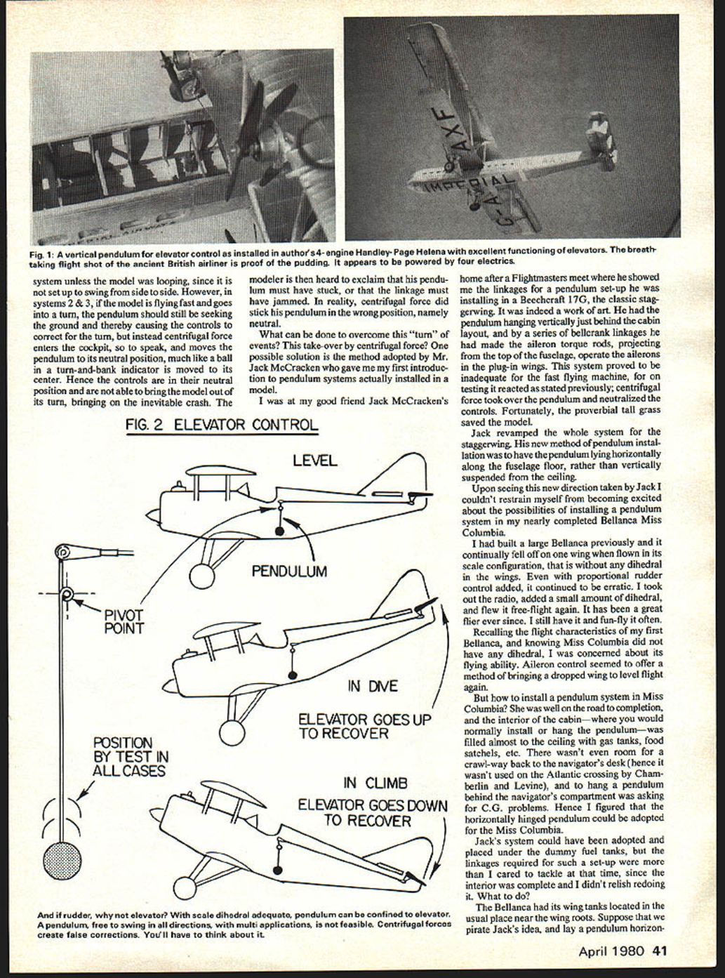
Most pendulum systems that I have read about depict the pendulum as hanging vertically from the top longerons in the open cockpit of the model, hinged so as to swing forward or backward depending on the attitude of the aircraft, and used in that mode to actuate the elevators. I used this system quite successfully in my four-engined Handley Page H.P. 42 Helena (see Fig. 1).
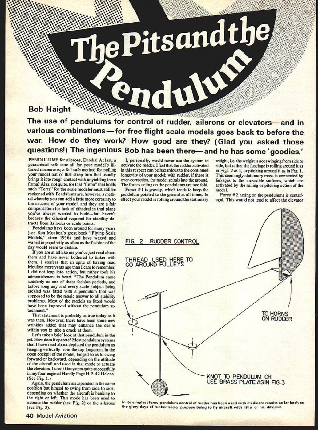
Again, the pendulum is suspended in the same position but hinged to swing from side to side, depending on whether the aircraft is banking to the right or left. This mode has been used to actuate the rudder (see Fig. 2) or the ailerons (see Fig. 3).
I, personally, would never use the system to activate the rudder. I feel that rudder activation in this respect can be hazardous to the continued longevity of your model; with rudder, if there is over-correction, the model can spiral into the ground.
The forces acting on the pendulums are twofold:
- Gravity — which tends to keep the pendulum pointed to the ground at all times. The effect is that your model rolls or pitches around the stationary weight: the weight is not swinging from side to side, but rather the fuselage is rolling around it (as in Figs. 2 & 3) or pitching around it (as in Fig. 1). This seemingly stationary mass is connected by linkages to the movable surfaces, which are activated by the rolling or pitching action of the model.
- Centrifugal force — which can counteract gravity in turns. This would not tend to affect the elevator system unless the model was looping, since it is not set up to swing from side to side. However, in side-to-side systems (used for ailerons or rudder), if the model is flying fast and goes into a turn, the pendulum should still be seeking the ground and thereby causing the controls to correct for the turn. Instead, centrifugal force enters the cockpit, so to speak, and moves the pendulum toward its neutral position, much like a ball in a turn-and-bank indicator is moved to its center. Hence the controls are in their neutral position and are not able to bring the model out of its turn, often bringing on the inevitable crash. The modeler is then heard to exclaim that his pendulum must have stuck, or that the linkage must have jammed. In reality, centrifugal force has neutralized his pendulum.
Overcoming centrifugal force — Jack McCracken's method
One possible solution is the method adopted by Jack McCracken, who gave me my first introduction to pendulum systems actually installed in a model.
At Jack's home after a Flightmasters meet he showed me the linkages for a pendulum set-up he was installing in a Beechcraft 17G, the classic staggerwing. He had the pendulum hanging vertically just behind the cabin layout, and by a series of bellcrank linkages he had made the aileron torque rods, projecting from the top of the fuselage, operate the ailerons in the plug-in wings. This system proved inadequate for the fast-flying machine: on testing, centrifugal force took over the pendulum and neutralized the controls. Fortunately, the proverbial tall grass saved the model.
Jack revamped the whole system for the staggerwing. His new method was to have the pendulum lying horizontally along the fuselage floor, rather than vertically suspended from the ceiling.
Upon seeing this new direction taken by Jack I couldn't restrain myself from becoming excited about the possibilities of installing a pendulum system in my nearly completed Bellanca Miss Columbia.
Wing-mounted horizontal pendulums (Miss Columbia)
I had built a large Bellanca previously and it continually fell off on one wing when flown in its scale configuration, that is with no dihedral in the wings. Even with proportional rudder control added, it continued to be erratic. I took out the radio, added a small amount of dihedral, and flew it free-flight again. It has been a great flier ever since. I still have it and fun-fly it often.
Recalling the flight characteristics of my first Bellanca, and knowing Miss Columbia did not have any dihedral, I was concerned about its flying ability. Aileron control seemed to offer a method of bringing a dropped wing to level flight again.
But how to install a pendulum system in Miss Columbia? She was well on the road to completion, and the interior of the cabin — where you would normally install or hang the pendulum — was filled almost to the ceiling with gas tanks, food satchels, etc. There wasn't even room for a crawl-way back to the navigator's desk (hence it wasn't used on the Atlantic crossing by Chamberlin and Levine), and to hang a pendulum behind the navigator's compartment was asking for C.G. problems. Hence I figured that the horizontally hinged pendulum could be adopted for the Miss Columbia.
Jack's system could have been adopted and placed under the dummy fuel tanks, but the linkages required for such a set-up were more than I cared to tackle at that time, since the interior was complete and I didn't relish redoing it. What to do?
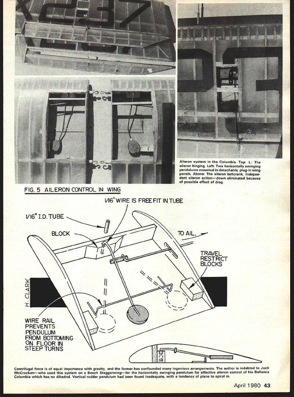
The Bellanca had its wing tanks located in the usual place near the wing roots. Suppose we pirate Jack's idea and lay a pendulum horizontally — only instead of one, we use two, one in each wing tank. It has the drawback of doubling the pendulum weights, but the advantage of being over the C.G., and also the absence of any linkages from a fuselage floor-up to wing connection.
There is also an advantage in the fact that the ailerons can be operated independently of one another with the ability to have differential movement. In the set-up I used I eliminated the use of "down" aileron completely in both wings, feeling that the down aileron might create more drag on the low wing, and increase or tighten the turn, thus overriding the effect of the aileron on the high wing. This would be particularly true, I think, in a slow-flying aircraft — at least that is the premise upon which I set up the system.
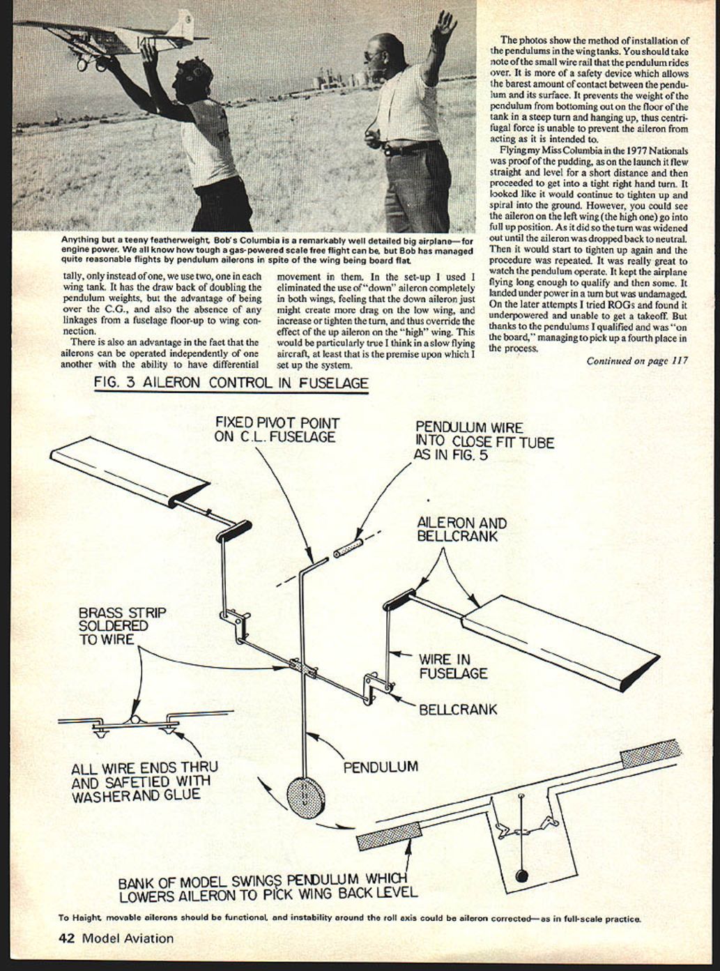
Anything but a teeny featherweight, my Columbia is a remarkably well-detailed big airplane for its engine power. We all know how tough a gas-powered scale free flight can be, but I managed quite reasonable flights by pendulum ailerons in spite of the wing being board flat.
The photos show the method of installation of the pendulums in the wing tanks. Note the small wire rail that the pendulum rides over. It is more of a safety device which allows the barest amount of contact between the pendulum and its surface. It prevents the weight of the pendulum from bottoming out on the floor of the tank in a steep turn and hanging up; thus centrifugal force is unable to prevent the aileron from acting as intended.
Observed flight behavior
Flying my Miss Columbia in the 1977 Nationals was proof of the pudding. On the launch it flew straight and level for a short distance and then proceeded to get into a tight right-hand turn. It looked like it would continue to tighten up and spiral into the ground. However, you could see the aileron on the left wing (the high one) go into full-up position. As it did so the turn was widened until the aileron dropped back to neutral. Then it would start to tighten again and the procedure was repeated. It was really great to watch the pendulum operate. It kept the airplane flying long enough to qualify and then some. It landed under power in a turn but was undamaged. On later attempts I tried ROGs and found it underpowered and unable to get a takeoff. But thanks to the pendulums I qualified and was "on the board," managing to pick up a fourth place in the process.
Figure 3 — Aileron control in fuselage (components and notes)
- Aileron and bellcrank
- Fixed pivot point on centerline of fuselage
- Pendulum
- Wire in fuselage
- Pendulum wire into close-fit tube (as in Fig. 5)
- Brass strip soldered to wire
- Bellcrank
- All wire ends through and safety-tied with washer and glue
- Function: Bank of model swings pendulum which lowers the aileron to pick the wing back level
In flight, movable ailerons should be functional; instability around the roll axis can be corrected with ailerons, as in full-scale practice. Centrifugal force is of equal importance with gravity, and the former has confounded many ingenious arrangements.
Pendulums/Haight
Jack has had similar success with his Beechcraft since he revamped his pendulum system, and since his aircraft flies at a much higher speed than mine, it speaks well of the system's ability to overcome the effects of centrifugal force.
There has been some concern that pendulums installed in this horizontal mode might exacerbate the effect of a stalled wing by driving it deeper until the model hit the ground. I do not believe this to be the case. An examination of the dynamics shows that such an effect would be unlikely, and in any event the pendulum is designed to be a corrective device; it moves the control in opposition to the deviation which the model is undergoing.
That is, the fear that a dive would actuate the pendulums and increase the hazard is misplaced. If the aircraft is in a steep dive, you already have your hands full on a model that is clearly out of trim. In any case, the ailerons will still operate to bring a wing up and at least try to keep a spiral dive from developing.
The model in this dive is in effect trying to turn away from the pendulums, and this would tend to keep them in neutral until a wing dropped, whereon they would operate to pick up that wing; however, they would have no effect on pitch or yaw and you would still have a crash on your hands if the aircraft is unrecoverable.
Mounting angle and placement
I loosely use the word "horizontally" to describe the pendulum, as you can see from Figs. 4 & 5: the pendulum is hanging at least 15° to 20° down from its pivot, so that it can accommodate the glide angle (any glide steeper than that and you're in trouble on your own). This angle is necessarily restricted if you mount the pendulum in the wing by the depth of the ribs themselves, but in large models such as the Bellanca this should pose no problem. If it does, then simply use Jack's system and mount it in the fuselage where there is ample room.
Construction and installation cautions
- Use heavy enough wire for all parts in the mechanical system itself. The connecting piece from the pendulum to the bellcrank sees a lot of pressure; a light or small connecting wire will flex or bend under flight loads rather than operate the aileron. Heavy wire should also be used on the pendulum itself to permit it to carry the weight and to prevent flexing under load.
- Build the bellcrank sturdily. I made the mistake of using clear plastic for the first ones and had to replace them as they broke under the slightest impact. Access panels over the cranks proved extremely valuable, allowing for small openings in the wing for easy replacement of parts.
- Be sure there is no "slop" in the system. A little play in the first bearing, a smidge more in the rod connecting the crank, etc., keeps multiplying until the whole system is rendered next to useless by cumulative play.
- On elevator systems I use an RC-type clevis which allows adjustment of up or down in the elevator. This really works great, allowing you to crank in the amount of elevator needed for flying from ROG. With pendulum elevators it is almost mandatory to ROG, since on running and hand-launching the pendulum is thrown to the back, giving down elevator and sending your pride and joy into the ground.
- Make sure there is no binding of the hinges on the ailerons or the elevators and that they move very freely. I have used a system that I consider both easy to install and absolutely free of binding: use small cotter pins inserted in the wing aileron spar, spread out on the back side through a small piece of light plywood so the small heads protrude from the spar; do the same on the ailerons themselves. When the ailerons are put on the wing the cotter pin heads are next to each other. Then run a long thin wire through the aligned holes, bend over the end of the wire that protrudes at the wing tip or elevator tip, and fasten it with a piece of Scotch tape, making them easily removable if necessary. This method avoids binding and the hinge wire falling out, and is nearly invisible.
- Use stops to restrict the movement of the pendulum. I use balsa blocks and can slice off a piece if more movement is required or glue another piece on to restrict it further.
- For bearings where your connecting wire passes through wing ribs or fuselage formers, I prefer to put large holes in the respective parts so the wire does not touch anything between the pendulum and the bellcrank or elevator horn. That is another reason I recommend using heavy wire between these points. If you use tubing bearings, make sure they are in direct line; if just one is out of line it will tend to bind up the entire system.
As the famous designer Bill Stout said, "Simplicate and add more lightness." That is sound advice for all scale modelers.
Jack has had success with his Beechcraft since changing to the horizontal pendulum, and my experiences with Miss Columbia suggest the method is a valuable option when dihedral cannot be used or when interior space requires creative solutions.
Transcribed from original scans by AI. Minor OCR errors may remain.

