
Plane Talk: 1/4-scale Fokker D.VII
Jerrold Smith
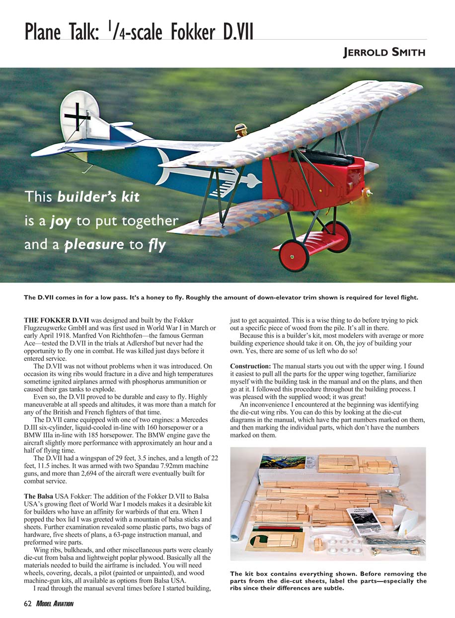
THE FOKKER D.VII was designed and built by the Fokker Flugzeugwerke GmbH and was first used in World War I in March or early April 1918. Manfred von Richthofen—the famous German ace—tested the D.VII in the trials at Adlershof but never had the opportunity to fly one in combat. He was killed just days before it entered service.
The D.VII was not without problems when it was introduced. On occasion its wing ribs would fracture in a dive and high temperatures sometimes ignited airplanes armed with phosphorus ammunition or caused their gas tanks to explode. Even so, the D.VII proved to be durable and easy to fly. Highly maneuverable at all speeds and altitudes, it was more than a match for any of the British and French fighters of that time.
The D.VII came equipped with one of two engines: a Mercedes D.III six-cylinder, liquid-cooled in-line with 160 horsepower, or a BMW IIIa in-line with 185 horsepower. The BMW engine gave the aircraft slightly more performance with approximately an hour and a half of flying time.
The D.VII had a wingspan of 29 feet 3.5 inches and a length of 22 feet 11.5 inches. It was armed with two Spandau 7.92 mm machine guns, and more than 2,694 of the aircraft were eventually built for combat service.
The Balsa USA Fokker
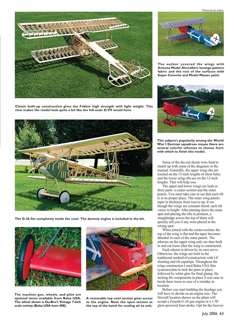
The addition of the Fokker D.VII to Balsa USA’s growing fleet of World War I models makes it a desirable kit for builders who have an affinity for warbirds of that era. When I popped the box lid I was greeted with a mountain of balsa sticks and sheets. Further examination revealed some plastic parts, two bags of hardware, five sheets of plans, a 63-page instruction manual, and preformed wire parts.
The kit includes:
- Die-cut wing ribs, bulkheads, and other miscellaneous parts cleanly cut from balsa and lightweight poplar plywood.
- Plastic parts, preformed wire parts, and hardware.
- Five sheets of plans and a 63-page instruction manual.
Basically all the materials needed to build the airframe are included. You will need the following extras (available as options from Balsa USA):
- Wheels
- Covering
- Decals
- A pilot (painted or unpainted)
- Wood machine-gun kits
I read through the manual several times before I started building, just to get acquainted. This is a wise thing to do before trying to pick out a specific piece of wood from the pile.
Because this is a builder’s kit, most modelers with average or more building experience should take it on. There are still some of us who enjoy building our own models!
Construction
The manual starts you out with the upper wing. I found it easiest to pull all the parts for the upper wing together, familiarize myself with the building task in the manual and on the plans, and then go at it. I followed this procedure throughout the build. I was pleased with the supplied wood; it was great.
An inconvenience I encountered at the beginning was identifying the die-cut wing ribs. You can do this by looking at the die-cut diagrams in the manual, which have the part numbers marked on them, and then marking the individual parts, which don’t have the numbers marked on them. Some of the die-cut sheets were hard to match up with some of the diagrams in the manual. Generally, the upper wing ribs are located on the 15-inch lengths of sheet balsa and the lower wing ribs are on the 12-inch lengths. That will help you.
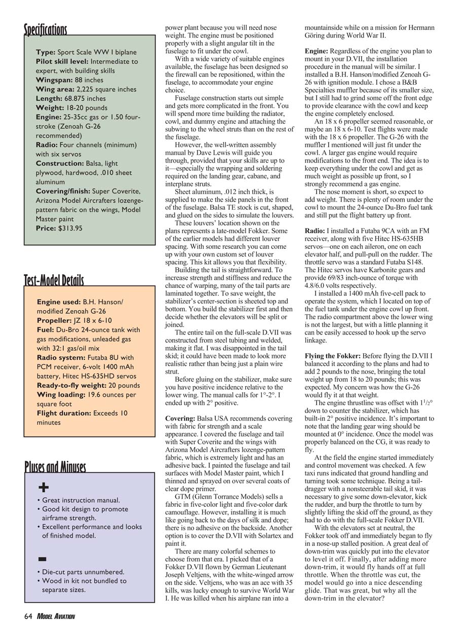
The upper and lower wings are built in three parts: a center section and the outer panels. You must take care to see that each rib is in its proper place. The outer wing panels taper in thickness from root to tip. Even though the wings are constant chord, each rib varies in height. After pinning down the main spar and placing the ribs in position, a straightedge across the top of them will quickly tell you if any were placed in the wrong spot.
When joined with the center section, the top of the wing is flat and the taper becomes dihedral in each of the outer panels. The ailerons on the upper wing only are then built in and cut loose after the wing is constructed. Each aileron is driven by its own servo. Otherwise, the wings are built in the traditional method of construction with leading-edge sheeting and rib cap strips.
Throughout the wing construction I used Balsa USA thin cyanoacrylate to tack the parts in place, followed by white glue for final gluing. By tacking the components in place it was easy to break them loose in case of a mistake in location.
Before you start building the fuselage you will have to decide on an engine size. The firewall location shown on the plans will accept a Zenoah G-26 gas engine or a 1.50 glow-powered four-stroke. Opt for the heavier power plant because you will need nose weight. The engine must be positioned properly with a slight angular tilt in the fuselage to fit under the cowl.
With a wide variety of suitable engines available, the fuselage has been designed so the firewall can be repositioned within the fuselage to accommodate your engine choice.
Fuselage construction starts out simple and gets more complicated in the front. You will spend more time building the radiator, cowl, and dummy engine and attaching the subwing to the wheel struts than on the rest of the fuselage.
The well-written assembly manual by Dave Lewis will guide you through, provided that your skills are up to it—especially the wrapping and soldering required on the landing gear, cabane, and interplane struts.
Sheet aluminum, .012 inch thick, is supplied to make the side panels in the front of the fuselage. Balsa TE stock is cut, shaped, and glued on the sides to simulate the louvers.
The louvers’ location shown on the plans represents a late-model Fokker. Some earlier models had different louver spacing. With some research you can come up with your own custom louver spacing. This kit allows you that flexibility.
Building the tail is straightforward. To increase strength and stiffness and reduce the chance of warping, many of the tail parts are laminated together. To save weight, the stabilizer’s center section is sheeted top and bottom. You build the stabilizer first and then decide whether the elevators will be split or joined.
The entire tail on the full-scale D.VII was constructed from steel tubing and welded, making it flat. I was disappointed in the tail skid; it could have been made to look more realistic rather than being just a plain wire strut.
Before gluing on the stabilizer, make sure you have positive incidence relative to the lower wing. The manual calls for 1°–2°. I ended up with 2° positive.
Covering
Balsa USA recommends covering with fabric for strength and a scale appearance. I covered the fuselage and tail with Super Coverite and the wings with Arizona Model Aircrafters lozenge-pattern fabric, which is extremely light and has an adhesive back. I painted the fuselage and tail surfaces with Model Master paint, which I thinned and sprayed on over several coats of clear dope primer.
GTM (Glenn Torrance Models) sells a fabric in five-color light and five-color dark camouflage. However, installing it is much like going back to the days of silk and dope; there is no adhesive on the backside. Another option is to cover the D.VII with Solartex and paint it.
There are many colorful schemes to choose from that era. I picked that of a Fokker D.VII flown by German Lieutenant Joseph Veltjens, with the white-winged arrow on the side. Veltjens, who was an ace with 35 kills, was lucky enough to survive World War I. He was killed when his airplane ran into a mountainside while on a mission for Hermann Göring during World War II.
Engine
Regardless of the engine you plan to mount in your D.VII, the installation procedure in the manual will be similar. I installed a B.H. Hanson–modified Zenoah G-26 with ignition module. I chose a B&B Specialties muffler because of its smaller size, but I still had to grind some off the front edge to provide clearance with the cowl and keep the engine completely enclosed.
An 18 x 6 propeller seemed reasonable, or maybe an 18 x 6–10. Test flights were made with the 18 x 6 propeller. The G-26 with the muffler I mentioned will just fit under the cowl. A larger gas engine would require modifications to the front end. The idea is to keep everything under the cowl and get as much weight as possible up front, so I strongly recommend a gas engine.
The nose moment is short, so expect to add weight. There is plenty of room under the cowl to mount the 24-ounce Du-Bro fuel tank and still put the flight battery up front.
Radio
I installed a Futaba 9CA with an FM receiver, along with five Hitec HS-635HB servos—one on each aileron, one on each elevator half, and pull-pull on the rudder. The throttle servo was a standard Futaba S148. The Hitec servos have Karbonite gears and provide 69/83 inch-ounces of torque with 4.8/6.0 volts respectively.
I installed a 1,400 mAh five-cell pack to operate the system, which I located on top of the fuel tank under the engine cowl up front. The radio compartment above the lower wing is not large, but with a little planning it can be easily accessed to hook up the servo linkage.
Flying the Fokker
Before flying the D.VII I balanced it according to the plans and had to add 2 pounds to the nose, bringing the total weight up from 18 to 20 pounds; this was expected. My concern was how the G-26 would perform at that weight.
The engine thrustline was offset 1½° down to counter the stabilizer, which has built-in 2° positive incidence. It’s important to note that the landing gear wing should be mounted at 0° incidence. Once the model was properly balanced on the CG, it was ready to fly.
At the field the engine started immediately and control movement was checked. A few taxi runs indicated that ground handling and turning took some technique. Being a taildragger with a nonsteerable tail skid, it was necessary to use some up-elevator, kick the rudder, and burn the throttle to keep it rolling, slightly lifting the skids off the ground as they had to do with the full-scale Fokker D.VII.
With the elevators at neutral, the Fokker took off on a three-point roll in a nose-up stalled position. A great deal of down-trim was quickly put into the elevator to level it off. Finally, after adding more down-trim, it would fly hands off at full throttle. When the throttle was cut, the model would go into a nice descending glide.
The manual strongly encourages you to add downthrust and gives you three options to check out. So I added another degree of downthrust, making it 2½°. The next test flight indicated less down-elevator, but it was not completely eliminated. Most of the Fokker D.VII owners I talked to said they flew with a slight amount of down in the elevator. We left it at these settings and went on to fly some maneuvers.
The D.VII is capable of all standard World War I–style maneuvers. You will have no trouble doing stall turns, split S’s, loops, barrel rolls, Immelmann turns, and, best of all, slow flybys.
When it comes time to land, keep a little power on until the wheels touch. The D.VII has a high drag factor and bleeds off speed quickly. When in ground effect, ease in some elevator and flare for a wheel or a three-point landing. To avoid ground looping, be ready with the rudder to keep the rollout straight.
I thank my good friend and fellow club member John Mueller for helping me with this review. With his flying skills I was able to photograph the flight shots. The color scheme on the D.VII was his idea, which I thought was outstanding. John is also an excellent builder.
Balsa USA has done a creditable job of producing a kit that should prove popular with World War I enthusiasts. During construction I found a couple things that could be improved:
- The wood in the kit is not organized by common sizes. It would be less time consuming for the builder if related sizes were bundled.
- A scale tail skid instead of a plain wire strut would be a welcome detail.
- The die-cut parts are unmarked; marking them would save time and frustration.
The assembly manual by Dave Lewis was excellent, providing step-by-step construction with good, clear pictures. He included some historical commentary about the Fokker D.VII, which makes the build more interesting as you progress.
This is a builder’s kit, and it requires considerable time to assemble with various skills involved. There are few of us modelers left who find joy in building, knowing the feeling and gratification of having done it ourselves.
If you are a builder, you will enjoy putting the Balsa USA Fokker D.VII together. It was a classic and colorful airplane of the era with much history, and it was widely regarded as the best German fighter of World War I. The kit is a good value, as are all Balsa USA kits, so why not buy one and build your own for a change? It’s worth the effort.
Jerrold Smith [email protected]
Manufacturer/Distributor
Balsa USA Box 164 Marinette, WI 54143 (800) 255-7287 www.balsausa.com
Sources
- Arizona Model Aircrafters
(602) 971-5646 www.arizonamodels.com
- GTM (Glenn Torrance Models)
(919) 423-8530 [email protected]
- B.H. Hanson
(702) 436-4422 www.bhhanson.com
- B&B Specialties
(574) 277-0499 www.bennettbuilt.com
- Du-Bro Products
(800) 848-9411 www.dubro.com
- Futaba (Great Planes)
(217) 398-8970 www.futaba-rc.com
- Hitec
(858) 748-6948 www.hitecrcd.com
Transcribed from original scans by AI. Minor OCR errors may remain.

